1
P-2-RSM:TEMPLATE
4/22/09
8:37 AM
Page 2
1.2 RSM FUNCTION
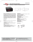
The Series RSM senses very low differential pressure using high
accuracy capacitive sensor technology. The pressure difference
for these applications is the difference in static pressure
between a critical environment room and its surrounding
reference area (usually a hallway or another room). Maintaining
and monitoring a static room pressure difference ensures that
the critical environment room is either protected or isolated from
a surrounding environment. Protection strategy requires a net
positive room static pressure difference, while isolation requires
a net negative static pressure difference. The RSM can be
programmed to monitor either positive or negative room static
pressure. The RSM low pressure sensing technology is coupled
with multifunctional alarming and simple touch-screen user
interface with password security protection.
2.0 PARTS LIST
2.1 RSM INCLUDED PARTS
Quantity
1 RSM assembly
2 Barbed Coupling, Brass
2 1/4 inch Tube, Silicone, Inter-Connect
4 6-32 x 1/2” Mounting Screws for RSM Base
2.2 A-285 INCLUDED PARTS
Quantity
1 Annunciator Assembly
3.0 MOUNTING AND WIRING
To mount and install properly, the following components are
required:
3.1 NOT INCLUDED RSM PARTS
Quantity
1 Double Gang Metal Electrical Box with Grounding Stud
1 4 x 4 inch Metal Plaster Ring
1 Door Switch SPDT or SPST, N.O., as needed
3.1 MOUNTING
CAUTION! (For 120/240 VAC Version Only): Do
not open or remove RSM cover (flathead
screwdriver required) with input power applied
unless performed by a licensed electrician.
“Hazardous Live” voltage is present at connector J3
when power is applied. Please observe the warning
symbol (
) near the J3 power connector.
The RSM is designed to be mounted on a standard double gang
metal electrical box using a 4 x 4 inch plaster ring adaptor.
Remove the RSM cover and mount the baseplate to the plaster
ring adaptor using four 6-32, 1/2˝ long mounting screws. Note:
The plaster ring external mounting face needs to be positioned
flush to recessed, relative to the surface of the wall. Also note
the orientation of the 4 mounting screws in the plaster ring, as
the plaster ring is rotated 90° from conventional mounting.
3.2 WIRING ELECTRICAL BOX (ROUGH IN)
Pre-wire electrical box with power (24 VAC or 120/240 VAC
depending on RSM model), and provide grounding to the
electrical box and plaster ring adaptor. The safety ground path
consists of the four 6-32 x 1/2˝ metal screws that connect the
RSM metal base to the 4˝ x 4˝ metal plaster ring. The plaster
ring is grounded to the 4˝ x 4˝ electrical box by 2 mounting
screws. The 4˝ x 4˝ electrical box is grounded to the building
earth ground.
Power leads and wiring should be 14 to 22 AWG braided wire.
18 AWG braided wire is recommended for wiring J3 power
connector to RSM. For 120/240 VAC the hot wire connects to L
and neutral to N (See Section 13.0).
3.2 NOT INCLUDED A-285 PARTS
Quantity
1 Single Gang Electrical Box
Note: In the following wiring sections, abbreviations are used
(e.g. J1, P3). Please see section 13.0 for complete wiring
diagrams with abbreviations.
Mounting Screws [x 4]