1
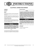
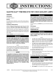
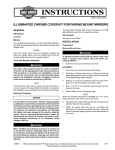
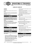
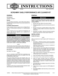
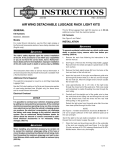
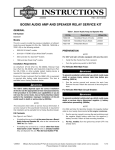
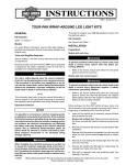
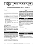
-J04456
REV. 2011-06-30
ROAD ZEPPELIN SEAT
Kit Contents
GENERAL
Kit Number
51072-09
Models
For model fitment information, see the P&A Retail Catalog or
the Parts and Accessories section of www.harley-davidson.com
(English only).
There are no serviceable parts inside the unit; leave all
servicing to qualified service personnel. Disassembly of
the unit could result in equipment damage and/or equipment malfunction. (00172a)
•
Additional Parts Required
Disassembly of the seat will void the manufacturer's
warranty.
See Figure 8 and Table 1.
REMOVAL
It is possible to overload your vehicle's charging system
by adding too many electrical accessories. If the combined
electrical accessories operating at any one time consume
more electrical current than the vehicle's charging system
can produce, the electrical consumption can discharge
the battery and cause damage to the vehicle's electrical
system. See an authorized Harley-Davidson dealer for
advice about the amount of current consumed by additional electrical accessories or for necessary wiring
changes. (00211c)
When installing any electrical accessory, be certain not
to exceed the maximum amperage rating of the fuse or
circuit breaker protecting the affected circuit being modified. Exceeding the maximum amperage can lead to electrical failures, which could result in death or serious injury.
(00310a)
This Road Zeppelin Seat kit requires up to 6.0 amps additional
current from the electrical system.
Separate purchase of an accessory Y Connector (70264-94)
if additional accessories are to be connected to the accessory
circuit connector. See a Harley-Davidson dealer for more
information.
The rider's safety depends upon the correct installation
of this kit. Use the appropriate service manual procedures.
If the procedure is not within your capabilities or you do
not have the correct tools, have a Harley-Davidson dealer
perform the installation. Improper installation of this kit
could result in death or serious injury. (00333a)
NOTE
To prevent accidental vehicle start-up, which could cause
death or serious injury, remove main fuse before proceeding. (00251b)
1.
Remove main fuse following the instructions in the service
manual.
NOTE
Cover the painted surfaces with protective material to prevent
scratches or other damage.
2.
Remove the left and right side saddlebags following the
instructions in the owner's manual.
3.
See Figure 2. Remove the screw (1) and lockwashers (2)
securing the grab strap (3) to the bracket (4 or 6). Save
the hardware for installation.
4.
Remove the grab strap.
5.
Remove seat following the instructions in the service
manual.
6.
If equipped, remove fender trim strips:
a.
Cover the tip of a regular screwdriver with a piece of
tape to protect chrome and painted surfaces.
b.
See Figure 1. Insert the tip of the screw driver
between the chrome bezel and the rubber trim strip.
c.
Pry up the bezel enough to get a hold of it, then pull
it up and away from the rubber trim strip.
d.
Starting at either end, peel the rubber trim strip away
from the fender.
e.
Clean any remaining adhesive off of the fender using
an approximately 1:1 solution of distilled water and
isopropyl alcohol.
This instruction sheet references service manual information.
A service manual for your model motorcycle is required for this
installation and is available from a Harley-Davidson Dealer.
-J04456
1 of 4
is07046
Position the seat on the frame. Make sure the electrical
harness and connector are not pinched between the seat
and frame.
3.
Install the seat following the instructions in the service
manual.
After installing seat, pull upward on seat to be sure it is
locked in position. While riding, a loose seat can shift
causing loss of control, which could result in death or
serious injury. (00070b)
Figure 1. Remove Fender Trim Strip
is06068
5
2
2.
1
3
4
4.
Install seat mounting screw and tighten securely. If TourPak was loosened, tighten screws.
5.
See Figure 3. Install the grab strap behind the saddlebag
mounting bracket (4) using the holes shown.
6.
Tighten stock screws to 15-20 ft-lbs (20-27 Nm).
7.
Install main fuse.
is05968
1
7
2
6
1.
2.
3.
4.
5.
6.
7.
1
3
Stock screw
Stock lockwasher
Grab Strap
Bracket, 2009-Later Models
2009-Later Models
Bracket, 2008-Earlier Models
2008-Earlier Models
1. Accessory connector
Figure 4. Accessory Connector Location (Under Seat)
Figure 2. Grab Strap and Saddlebag Front Mounting
Bracket
is05860
1
2
3
OPERATION
The seat will operate with the ignition switch ON or in the
ACCESSORY position. For vehicles with a fairing, verify the
accessory switch in the fairing is ON. At start up, the compressor may operate briefly.
Press the raised surface of each button to inflate the chambers.
The flat side of the button deflates the chambers.
Rider Thigh Zone
1. 2008 mounting hole
2. 2009 mounting hole
3. 2008 and 2009 mounting hole
See Figure 5. The first button on the seat control panel inflates
and deflates the thigh chambers.
Figure 3. Grabstrap for Kit 53051-09
INSTALLATION
1.
See Figure 4. Remove rubber plug from accessory connector (1) located under seat. Plug the seat electrical
connector into the accessory connector. The connectors
should lock together with an audible click.
-J04456
2 of 4
Passenger Comfort: While seated but not moving:
is05969
•
Practice finding the switches without looking for the buttons.
•
Deflate all the chambers completely.
•
Adjust the thigh chamber to press firmly but comfortably
against you.
Troubleshooting
•
If the compressor continues to run without pressing the
inflation buttons, disconnect power to the seat immediately.
•
If the seat does not inflate either the rider or the passenger
areas when the inflation buttons are pressed, check all
electrical connections.
If any of these conditions persist, disconnect the seat electrical
power and return to the dealer for further investigation..
is05970
Figure 5. Rider Thigh Control
Rider Lower Back Zone
See Figure 6. The second button on the seat control panel
inflates and deflates the lower back chambers.
Passenger Thigh Zone
See Figure 7. The third button on the seat control panel inflates
and deflates the passenger chambers.
Riding Recommendations
Do not adjust seat while riding. Adjusting seat while riding
can distract the rider and lead to loss of control, which
could result in death or serious injury. (00598c)
Before you ride:
•
Deflate all chambers completely.
•
Adjust the thigh chamber to press firmly, but comfortably,
against you.
•
Adjust the lower back chamber to press comfortably
against you.
Figure 6. Rider Tailbone Zone
City Riding: When riding requires frequent stops, it may be
more comfortable to keep the thigh chamber only slightly filled
or empty.
Touring: Adjust the thigh chamber to apply firm but comfortable
pressure. If desired, adjust the lower back chambers while your
feet are in a touring position. On long rides, it may be desired
to adjust the seat at every rest stop to change position. This
will improve the blood circulation resulting in less fatigue and
improved long distance comfort.
-J04456
3 of 4
SERVICE PARTS
is05972
is05975
2
1
Figure 8. Service Parts: Road Zeppelin Seat
Table 1. Service Parts
Item
Figure 7. Passenger Thigh Zone
-J04456
Description
(Quantity)
Part Number
1
Seat
Not Sold Separately
2
Grabstrap
51051-09
4 of 4