1
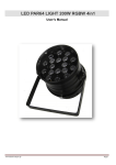
LED PAR 64 18x10W RGBW 4in1 IP65 F7000795 USER MANUAL / INSTRUKCJA OBSŁUGI LED PAR 64 18x10W RGBW 4in1 IP65 F7000795 Table of Contents 1 Introduction ...................................................................................................................................................... 2 2 Safety information ........................................................................................................................................... 2 3 Product information ........................................................................................................................................ 3 3.1 Specification ................................................................................................................................................ 3 4 Installation ........................................................................................................................................................ 3 5 Connections ...................................................................................................................................................... 4 5.1 Connecting DMX signal............................................................................................................................. 4 5.2 Voltage specification .................................................................................................................................. 5 5.3 Connecting power supply ........................................................................................................................ 5 6 Maintenance and Cleaning ............................................................................................................................. 5 7 Operation manual ............................................................................................................................................ 6 7.1 Control panel .............................................................................................................................................. 6 7.2 Menu ............................................................................................................................................................ 6 7.3 DMX channel list ........................................................................................................................................ 7 1 www.flash-butrym.pl 1 INTRODUCTION Thank you for purchasing this LED PAR 64. For safety reasons and to ensure the trouble-free operation, carefully read the instructions before installing the device. Please install and operate the fixture with following instructions. 2 SAFETY INFORMATION This device has left the factory in perfect condition. In order to maintain this condition and to ensure a safe operation, it is absolutely necessary for the user to follow the safety instructions and warning notes written in this user manual. IMPORTANT! Damages caused by the disregard of this user manual are not subject to warranty. The dealer will not accept liability for any resulting defects or problems. 1. 2. 3. 4. 5. 6. 7. 8. 9. 10. 11. 12. 13. 14. Installation should be done by qualified personnel in order to minimize the risk of accidental electric shock Disconnect the power supply before installation. Before connecting the unit to the mains, make sure it is not damaged mechanically. If you notice any signs of damage you should contact your dealer immediately. Do not connect the device to the mains. Do not use the device at temperatures above 35° C The device must be installed on stable structures. If the device has been exposed to temperature changes due to environmental changes, do not switch it on immediately. The arising condensation could damage the device. Leave the device switched off until it has reached room temperature. This device falls under protection-class I. Therefore it is essential that the device be earthed. The device shall only be used with rate voltage and frequency. Make sure that the available voltage is not higher than stated in this manual. Make sure the power cord is never crimped or damaged by sharp edges. If this would be the case, replacement of the cable must be done by an authorized dealer. Always disconnect from the mains, when the device is not in use or before cleaning it. Only handle the power cord by the plug. Never pull out the plug by tugging the power cord. Fixtures cannot be installed on combustible substances, keep more than 50cm distance with wall for smooth air flow, so there should be no shelter for fans and ventilation for heat radiation. If the external flexible cable or cord of this luminaire is damaged, it shall be exclusively replaced by the manufacturer or his service agent or a similar qualified person in order to avoid a hazard. www.flash-butrym.pl 2 LED PAR 64 18x10W RGBW 4in1 IP65 F7000795 3 PRODUCT INFORMATION This device is designed to provide extraordinarily technology and very high power LED. It is designed for outdoor use, for example to illuminate the facades of buildings. It can display static colors, and change the colors in automatic mode. The device uses powerful RGBW LEDs that dramatically improve the color mixing and extends color palette. The LED PAR 64 18x10W RGBW with IP65 is equipped with dedicated waterproof connectors that make this fixture suitable for outdoor use due to the protective grade of IP65. 3.1 Specification 4 Rated voltage: 95V-240V AC, 50/60Hz Power Consumption: 180W LED:18x10W RGBW 4in1 Beam Angle: 25° Strobe Pulse: 0-12Hz DMX512 Channels: 4 / 8 Function: Auto-run, DMX-512 control console, Sound-activated Protect Level: IP65 Work Environment: -25°C ~ +35°C Packing Size: 300x300x345mm Weight: 10Kg INSTALLATION When installing the unit please comply with the following rules: 1. 2. 3. 4. 5. 6. 7. 8. Don’t turn on the fixture if it’s been through severe temperature difference like after transportation because it might damage the light due to the environment changes. So make sure to operate the fixture until it is in normal temperature. Don’t expose the fixture in overheat when installing it. And don’t lay any power cables on the floor, or it might cause electronic shock. Make sure the installation place is in good safety condition before installing the fixture. Make sure to put the safety chain and check whether the screws are screwed properly when installing the fixture. Make sure the fixture is operated by qualified personnel who knows the fixture before using. Keep the original packages if any second shipment is needed. Don’t try to change the fixtures without any instruction by the manufacturer or the appointed service centers. It is not in warranty range if there are any malfunctions from not following the user manual to operate or any illegal operation, like shock short circuit, electronic shock, lamp broke, etc. After removing the packaging, check if the device was not damaged during transport. Before connecting to the mains, make sure that the device is securely mounted. The manufacturer is not responsible for damage caused by unstable mounting. Ensure proper connection to the mains and proper grounding. Make sure that the electrical parameters are consistent with device requirements. All activities, including connecting the device to the mains must be performed by qualified personnel. 3 www.flash-butrym.pl CAUTION! For added protection mount the fixtures in areas outside walking paths, seating areas, or in areas were the fixture might be reached by unauthorized personnel. Before mounting the fixture to any surface, make sure that the installation area can hold a minimum point load of 10 times the device’s weight. Fixture installation must always be secured with a secondary safety attachment, such as an appropriate safety cable. Never stand directly below the device when mounting, removing, or servicing the fixture from a periodic safety inspection of all installation material and the fixture. If you lack these qualifications, do not attempt the installation yourself. Improper installation can result in bodily injury. Be sure to complete all rigging and installation procedures before connecting the main power cord to the appropriate wall outlet. 5 CONNECTIONS The device is equipped with the following interfaces: 1. 2. 5.1 DMX (in/out): dedicated IP65 socket (XLR 3-pin socket input adapter included) Power (in/out): dedicated IP65 socket (Unischuko adapter included) Connecting DMX signal The connection is performed using cable with XLR-female -> XLR-Male plugs. Connect the provided XLR cable to the female 3-pin XLR output of your controller and the other side to the male 3-pin XLR input of the moving head. You can chain multiple devices. The cable should be two core, screened cable with XLR input and output connectors. Please refer to the diagram below. GROUND 1 1 DMX + 3 3 DMX - 2 2 FEMALE XLR MALE XLR DMX 512 DMX 512 DMX Controller www.flash-butrym.pl 4 LED PAR 64 18x10W RGBW 4in1 IP65 F7000795 For installations where the DMX cable has to run a long distance or is in an electrically noisy environment, such as in a discotheque, it is recommended to use a DMX terminator. This helps in preventing corruption of the digital control signal by electrical noise. The DMX terminator is simply an XLR plug with a 120 resistor connected between pins 2 and 3,which is then plugged into the output XLR socket of the last fixture in the chain. Please see illustrations below. 120Ω 3 2 1 5.2 Voltage specification 5.3 Input Voltage Total Power Frequency 95~240V 180W 50/60Hz Connecting power supply The connection is performed using dedicated power cable with with Unischuko plug (included). The device must be operated by qualified personnel. Make sure that the power grid supply parameters are consistent with device parameters and limitations are not exceeded. CAUTION! In the case of cable damage do not attempt to repair. Replacement or repair can be made only on the manufacturer or by a person with appropriate permissions. 6 MAINTENANCE AND CLEANING The following points have to be considered during the inspection: 1. 2. 3. 4. All screws for installing the devices or parts of the device have to be tightly connected and must not be corroded. There must not be any deformations on the housing, color lenses, fixations and installation spots (ceiling, suspension, trussing). The electric power supply cables must not show any damage, material fatigue or sediments. Further instructions depending on the installation spot and usage have to be adhered by a skilled installer and any safety problems have to be removed. CAUTION! Disconnect from mains before starting maintenance operation. In order to make the lights in good condition and extend the lifetime, we suggest a regular cleaning to the lights. 5 www.flash-butrym.pl We recommend a frequent cleaning of the device. Please use a moist, lint-free cloth. Never use alcohol or solvents. There are no serviceable parts inside the device. Please refer to the instructions under “Installation” instructions. If you need any spare parts, please order genuine parts from your local dealer. 7 OPERATION MANUAL 7.1 Control panel The control panel is equipped with LCD display and 4 control buttons with the following functions: 1. 2. 3. 4. 7.2 MENU – access the menu DOWN – “reduction key” or "key under the selected": decrease the value UP – “add key” or “selection on the key”: increase value ENTER – “OK button”: select function, confirm changes (stop the ongoing functions, run the function the user selected) Menu Menu diagram: dNNN → DMX address edit d001-d512 CHNd → 4 channel mode CH4d 8 channel mode CH8d AuNN StNN → Fixed colors Auto mode 1 Au09 Auto mode FADE Au10 Sound mode 1 So01 Sound mode 2 So02 → Strobe off Strobe slow to fast www.flash-butrym.pl Au01-Au08 St00 St01-St16 SpNN → Auto mode speed (Au09 –Au10) Sp00-Sp16 rNNN → Adjust brightness for Red color 000-255 GNNN → Adjust brightness for Green color 000-255 bNNN → Adjust brightness for Blue color 000-255 uNNN → Adjust brightness for White color 000-255 6 LED PAR 64 18x10W RGBW 4in1 IP65 F7000795 7.3 DMX channel list 4CH mode Channel CH 1 CH 2 CH 3 CH 4 Function Red dimmer Green dimmer Blue dimmer White dimmer Channel CH 1 CH 2 CH 3 CH 4 CH 5 CH 6 Function Dimmer Red dimmer Green dimmer Blue dimmer White dimmer Strobe CH 7 Program CH 8 Speed / Color Effect 0-255: 0-100% 0-255: 0-100% 0-255: 0-100% 0-255: 0-100% 8CH mode 7 Effect 0-255: 0-100% 0-255: 0-100% 0-255: 0-100% 0-255: 0-100% 0-255: 0-100% 0-255:1-20Hz 0-3: No funcion 4-127: Fixed color (set color using CH 8) 128-169: Auto mode 1 170-210: Auto mode 2 211-229: Sound mode 1 230-255: Sound mode 2 0-255: Set speed for Auto mode (CH 7) 0-32: Set color for Fixed color (CH 7) – color 1 33-63: Set color for Fixed color (CH 7) – color 2 64-95: Set color for Fixed color (CH 7) – color 3 96-127: Set color for Fixed color (CH 7) – color 4 128-159: Set color for Fixed color (CH 7) – color 5 160-191: Set color for Fixed color (CH 7) – color 6 192-223: Set color for Fixed color (CH 7) – color 7 224-255: Set color for Fixed color (CH 7) – color 8 www.flash-butrym.pl