1
Installation Instructions for
B.A.S.I.S. Cylindrical Locks
Planning the installation
Contents
Components checklist
These installation instructions describe how to install your
B.A.S.I.S.® G (93KG–95KG) or B.A.S.I.S. V (93KBV–95KBV)
Cylindrical Lock. The following topics are covered.†
Use the following checklist to make sure that you have the
items necessary to install your B.A.S.I.S. Cylindrical Lock.
Components provided in the box:
❑ Chassis with outside lever and outside rose liner
assembly
❑ Inside escutcheon assembly
❑ Battery compartment door
❑ Battery pack
❑ Inside rose liner
❑ Outside escutcheon assembly
❑ Inside lever
❑ Throw member package
❑ Latch
❑ Plastic bushing package
❑ Escutcheon screw package
❑ Strike package
❑ Bar code ID sticker (for your records)
❑ Temporary operator card
❑ Installation template and instructions
Other components:
❑ Core
❑ Control key
Planning the installation ................................................ 1
Preparing the door and door jamb ................................ 2
Installing the lock ............................................................ 6
Completing the installation............................................ 9
Site survey
Use the following survey to record information about the
installation site. You need this information to determine
how to prepare the door for the lock.
Door information
Door handing and bevel:
❑ Left hand (LH)
❑ Left hand, reverse bevel (LHRB)
❑ Right hand (RH)
❑ Right hand, reverse bevel (RHRB)
Door thickness:
inches (1 3/4″ to 2 1/4″)
Environment information
Ambient temperature:
❑ Is within specifications. See the tables below.
This product meets the following Locked Door Outdoor
test requirements for ANSI/BHMA 156.25:
Side of door
Inside
Outside
Range
+66°F to +74°F (+19°C to +23°C)
–31°F to +151°F (–35°C to +66°C)
This product meets the following Full Indoor test
requirements for ANSI/BHMA 156.25:
Side of door
Inside and outside
Range
+32°F to +120°F (0°C to +42°C)
Special tools checklist
Use the following checklist to make sure that you have the
special tools necessary to install your B.A.S.I.S. Cylindrical
Lock.
❑ KD303 Drill jig
❑ T15 TORX® bit driver‡
❑ KD325 Strike plate locating pin
❑ KD315 Faceplate marking chisel
† The Best Access Systems logo and B.A.S.I.S. are
registered trademarks of Best Lock Corporation.
‡ TORX is a registered trademark of the Camcar
Division of Textron.
BEST ACCESS SYSTEMS
Indianapolis, Indiana
1
Installation Instructions for B.A.S.I.S. Cylindrical Locks
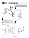
Preparing the door and door jamb
1
Installation template
Horizontal centerline
of lever
1
2
Figure 1
Positioning the template
3
4
Position template and mark drill points
Note: If the door is a fabricated hollow metal door,
determine whether it is properly reinforced to support
the lock. If door reinforcement is not adequate, consult
the door manufacturer for information on proper
reinforcement. For dimensions for preparing metal
doors, see the G01 and G02 Templates—Installation
Specifications for 93KG and 93KBV Cylindrical Locks.
Note: If the door is a LH or RH door, mark the inside of
the door. If the door is a LHRB or RHRB door, mark the
outside of the door.
For uncut doors and frames
Measure and mark the horizontal centerline of the
lever (the centerline for the chassis hole) on the door
and door jamb. Mark the vertical centerline of the door
edge.
Note: The recommended height from the floor to the
centerline of the lock is 38″.
Fold the G05 Template—Installation Template for 93KG
and 93KBV Cylindrical Locks on the dashed line and
carefully place it in position on the high side of the
door bevel.
Note: For steel frame applications, align the template’s
horizontal centerline for the latch with the horizontal
centerline of the frame’s strike preparation.
Tape the template to the door.
Center punch the necessary drill points. Refer to the
instructions on the template.
For doors with standard cylindrical preparation
1 Fold the G05 Template—Installation Template for 93KG
and 93KBV Cylindrical Locks on the dashed line.
Looking through the hole from the opposite side of
the door, align the template so that you see the
template outline of the 2 1/8″ diameter chassis hole.
2 Tape the template to the door.
3 Center punch the necessary drill points. Refer to the
instructions on the template.
2
BEST ACCESS SYSTEMS
Indianapolis, Indiana
Installation Instructions for B.A.S.I.S. Cylindrical Locks
Preparing the door and door jamb
2
Components checklist
Drill holes and mortise for latch face.
1 Drill the holes listed below:
■ upper and lower trim holes
— 5/8″ diameter
— through door
■ harness hole
— 3/4″ diameter
— through door
— location based on handing
■ motor wire hole
— 7/16″ diameter
— through door
— before drilling chassis hole
■ chassis hole
— 2 1/8″ diameter
— through door
— after drilling motor wire hole
■ latch hole
— 1″ diameter
— meets chassis hole
Upper trim hole
Harness
hole
Motor wire hole
Latch hole
Chassis hole
Latch face
mortise
Lower trim hole
Inside of door
Figure 2
Drilling holes and mortising for the latch face
Note 1: To locate the center of a hole on the opposite
side of the door, drill a pilot hole completely through the
door.
Note 2: For holes through the door, it is best to drill
halfway from each side of the door to prevent the door
from splintering.
2 Mortise the edge of the door to fit the latch face.
3 Drill the holes for the screws used to install the latch.
BEST ACCESS SYSTEMS
Indianapolis, Indiana
3
Installation Instructions for B.A.S.I.S. Cylindrical Locks
Preparing the door and door jamb
3
Install latch
1 Install the latch in the door.
Note: The latch tube prongs should be centered and
should project into the chassis hole.
2 Check that the door swings freely.
Chassis hole
Location of latch
tube prongs
Latch
Inside of door
Figure 3
Installing the latch in the door
4
Drill upper through-bolt hole.
Latch
tube
prongs
Use drill jig to drill through-bolt holes
1 Press the drill jig (KD303) onto the door, engaging it
with the latch tube prongs (see the close-up in
Figure 4). Make sure the front edge of the jig is parallel
with the door edge.
2 Drill the through-bolt holes (5/16″ diameter) halfway
into the door.
3 Turn over the drill jig and repeat steps 1 and 2 from the
opposite side of the door.
Note: Replace the drill jig after 10 door preparations.
Drill lower through-bolt hole.
Inside of door
Figure 4
4
Installing the drill jig and drilling the
through-bolt holes
BEST ACCESS SYSTEMS
Indianapolis, Indiana
Installation Instructions for B.A.S.I.S. Cylindrical Locks
Preparing the door and door jamb
5
Install strike box and strike plate
1 In alignment with the center of the latchbolt, mortise
the door jamb to fit the strike box and strike plate.
2 Drill the holes for the screws used to install the strike
box and strike plate.
3 Insert the strike box and secure the strike with the two
screws provided.
4 Check the position of the deadlocking plunger against
the strike plate.
Caution: The deadlocking plunger of the latchbolt
must make contact with the strike plate, as shown
in Figure 5b. The plunger deadlocks the latchbolt
and prevents someone from forcing the latch
open when the door is closed.
Strike box
Strike plate
Door jamb
Figure 5a Installing the strike box and strike plate
Deadlocking
plunger
Strike plate
Door jamb
Figure 5b Aligning the deadlocking plunger with the
strike plate
BEST ACCESS SYSTEMS
Indianapolis, Indiana
5
Installation Instructions for B.A.S.I.S. Cylindrical Locks
Installing the lock
6
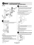
1 Insert the control key into the core and rotate the key
15 degrees to the right.
2 Insert a flat blade screwdriver into the figure-8 core
hole and into the lever.
3 Press the screwdriver blade in the direction of the
arrow in Figure 6.
Note: You cannot remove the lever if the screwdriver
blade is inserted too far past the keeper.
4 Slide the lever off of the sleeve.
Lever keeper
Insert screwdriver
blade here.
Figure-8
core hole
Figure 6
Removing the outside lever
7
2 1/4″ groove
2″
1 3/4″
Remove outside lever
Adjust for door thickness
1 Determine the door’s thickness.
2 Pull the rose locking pin and rotate the outside rose
liner until the proper groove on the through-bolt stud
lines up with the hub face.
Throughbolt stud
Hub face
Note 1: Make sure that the locking pin fully locks into
the rose liner.
Note 2: The lockset fits doors 1 3/4″ to 2 1/4″ thick.
Outside
rose liner
Figure 7
6
Rose locking
pin
Adjusting the rose liner for the door thickness
BEST ACCESS SYSTEMS
Indianapolis, Indiana
Installation Instructions for B.A.S.I.S. Cylindrical Locks
Installing the lock
8
Install lock chassis and engage
retractor in latch
Retractor
Latch tube
prong
Latch
tailpiece
From the outside of the door, insert the lock chassis
into the 2 1/8″ chassis hole, routing the motor wire
through the notch.
Caution: Make sure that the latch tube prongs
engage the chassis frame and that the latch
tailpiece engages the retractor.
Latch tube
prong
Chassis frame
Notch
Chassis
Inside of door
Figure 8
9
Installing the lock chassis and engaging the
retractor in the latch
Install through-bolts and inside rose
liner
1 Place the inside rose liner on the chassis, aligning the
holes in the rose liner with the holes prepared in the
door.
Caution: Make sure that there is clearance for the
motor wire between the rose liner and the door.
2 Install the through-bolts through the rose liner and
door in the top and bottom holes.
3 Tighten the rose liner on the door with the
through-bolts.
Motor wire
Through-bolt
Rose liner
Figure 9
BEST ACCESS SYSTEMS
Indianapolis, Indiana
Inside of door
Installing the through-bolts and rose liner
7
Installation Instructions for B.A.S.I.S. Cylindrical Locks
Installing the lock
10
Battery connector
Motor connector
Upgrade
connector
Harness hole
Bushing
Caution 1: For the lock to operate properly, you
must remove the backup battery tab.
Caution 2: Do not connect the battery pack before
you have removed the backup battery tab. Doing so
may cause the lock to malfunction.
1 Locate the backup battery tab on the inside of the outside
escutcheon.
2 Pull down on the tab and remove it from the outside
escutcheon to turn on the backup battery.
11
Outside escutcheon
Outside of door
Figure 11 Feeding the wire harness connectors through
the harness hole
Upgrade cable
Motor connection
Inside of door
Route wire harness and position outside
escutcheon
1 Insert the two bushings into the harness hole on each side
of the door, as shown in Figure 11 and Figure 12.
2 From the outside of the door, feed the upgrade connector,
and then the motor connector and battery connector,
through the harness hole.
Caution: When routing the connectors, make sure
the wire harness is not routed across any sharp edges
or over any surface that could damage its sleeving or
wire insulation.
3 Temporarily rest the outside escutcheon on the door by
inserting the trim studs into the trim holes.
Note: You can temporarily install the outside lever to hold
the outside escutcheon in place. See task 15 on page 10.
12
Bushing
Remove backup battery tab
Make motor connection
From the inside of the door, connect the motor connector
from the chassis to its mating connector on the wire
harness.
Note 1: The upgrade cable is used for reprogramming the
lock’s firmware without removing the lock from the door.
This cable does not connect to a mating lock connector.
Note 2: The motor connection has 2 wires and 2 pins. The
wire colors are yellow and gray.
Caution: When making the motor connection, make
sure:
■ there are no loose wire connections where the
wires are inserted into the connectors
■ the connectors are firmly mated.
Figure 12 Making the motor connection
8
BEST ACCESS SYSTEMS
Indianapolis, Indiana
Installation Instructions for B.A.S.I.S. Cylindrical Locks
Installing the lock
13
Secure escutcheons
1 Position the inside and outside escutcheons on the
door.
2 Making sure that the escutcheons do not pinch
the wires, secure the escutcheons to the door—but
do not tighten. Use the combination mounting screw
at the upper trim hole and the standard mounting
screw at the lower trim hole.
Inside escutcheon
Combination
mounting screw
Standard
mounting screw
Inside of door
Figure 13 Securing the escutcheons
14
Install battery pack
1 Connect the battery pack to the battery connector on
the wire harness inside the battery compartment.
Note: The battery connection has 3 wires and 3 pins. The
wire colors are:
■ red with white stripe
■ white
■ black with white stripe.
Caution: When connecting the battery pack, make
sure:
■ there are no loose wire connections where the
wires are inserted into the connectors
■ the connectors are firmly mated.
2 Place the battery pack inside the battery compartment
so that the foam will face the battery compartment
door.
Caution: When routing the battery wires, make
sure the wires are not routed across any sharp
edges or over any surface that could damage their
sleeving or wire insulation.
Inside escutcheon
Battery pack
Figure 14 Connecting the battery pack
BEST ACCESS SYSTEMS
Indianapolis, Indiana
9
Installation Instructions for B.A.S.I.S. Cylindrical Locks
Completing the installation
15
Install inside and outside levers
Note: To use a core and throw member from a
manufacturer other than BEST with a B.A.S.I.S. Lock, see
the Installation Instructions for 9K Noninterchangeable Cores & Throw Members (T56093).
Skip task 15 and task 16.
For the inside and outside levers
1 With the handle pointing toward the door hinges,
position a lever on the outside sleeve and push firmly
on the lever until it is seated. Repeat, placing the other
lever on the inside sleeve.
2 Tighten the escutcheon mounting screws.
3 Turn the levers to check that they operate smoothly.
Outside of door
Figure 15 Installing the levers
16
Core
Blocking
plate
Throw
member
Figure 16a Installing the blocking plate and throw
member
Throw
member
Core
Install core and throw member
1 Install the blocking plate onto the throw member.
Caution: You must use the blocking plate to
prevent unauthorized access.
2 Insert the control key into the core and rotate the key
15 degrees to the right.
3 Insert the throw member into the core.
4 Insert the core and throw member into the lever with
the control key.
5 Rotate the control key 15 degrees to the left and
withdraw the key.
Caution: The control key can be used to remove
cores and to access doors. Provide adequate
security for the control key.
Control
key
Figure 16b Installing the core
10
BEST ACCESS SYSTEMS
Indianapolis, Indiana
Installation Instructions for B.A.S.I.S. Cylindrical Locks
Completing the installation
17
Install battery compartment door
1 Making sure that the battery compartment door
does not pinch any wires, insert the tabs of the
battery compartment door into its mating slots and
swing the door closed.
2 Use a T15 TORX bit driver to secure the battery
compartment door with the security screw. Tighten
firmly.
Security
screw
Tabs
Figure 17 Installing the battery compartment door
BEST ACCESS SYSTEMS
Indianapolis, Indiana
11
Installation Instructions for B.A.S.I.S. Cylindrical Locks
Completing the installation
18
Test lock
To test the lock for proper operation before the lock is
programmed, use the temporary operator card that came
with the lock. This card is for temporary use only. After
permanent cards have been programmed for the lock, the
temporary card should be deleted.
1 Use the temporary operator card to activate the lock.
When the lock detect the presence of a card for the
first time, it performs a series of diagnostic self-tests. If
no problem is detected, the lock responds with 4 red
LED flashes, simultaneous with 4 green LED flashes
and 4 short tones.
If a problem is detected, the lock’s red LED and
green LED simultaneously flash in a repeating pattern
(and no tones sound). The lock’s control electronics
board must be replaced. For instructions, see the
B.A.S.I.S. G Service Manual (T63300) or the B.A.S.I.S. V
Service Manual (T61805).
Note: If the lock has a proximity card reader, it may have
already been activated by the presence of an object near
the card reader.
2 Use the temporary operator card to access the lock.
The green light flashes and the locking mechanism
unlocks.
3 Turn the lever and open the door.
4 With the door closed, insert and turn the key to
unlatch the door.
If the mechanism doesn’t unlock, refer to the
following table. For additional troubleshooting
instructions, see the B.A.S.I.S. G Service Manual or the
B.A.S.I.S. V Service Manual.
LEDs
Sounder
Single
red flash
—
Use the card at a moderate speed.
Red
flashes
3 short
tones
Use the temporary operator card
provided with the lock.
Green
flashes
—
Check the motor connection.
—
—
Check the battery connection.
12
You should
© 2000–2001 Best Lock Corporation dba Best Access Systems.
T63301/Rev D 1819347 ER-7991-12 November 2001
BEST ACCESS SYSTEMS
Indianapolis, Indiana