1
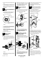
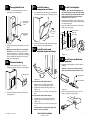
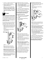
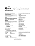
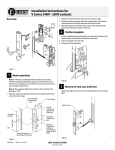
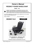
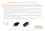
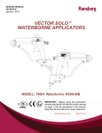
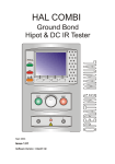
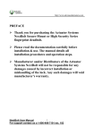
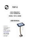
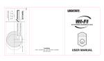
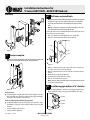
Installation Instructions for
V Series 83KV/93KV–85KV/95KV locksets
Overview
2
Drill holes and install latch
Note 1: Determine whether fabricated hollow metal doors are properly
reinforced to support the lock. If door reinforcement is not adequate,
consult the door manufacturer for information on proper reinforcement.
Note 2: To locate the centerpoint of a hole on the opposite side of the
door, drill a pilot hole completely through the door.
For through-holes, it is best to drill halfway from each side of the door to
prevent the door from splintering.
1 Drill a 3/8" diameter hole through the door for motor wires.
2 Bore the 2 1/8" diameter hole (if not already drilled).
7/8"
2 1/8"
1"
Figure 1
1
5/8"
3/8"
Position template
Note: On steel frame applications, align the horizontal centerline of the
latch with the horizontal centerline of the strike preparation.
Figure 3
3 Drill the 1" diameter hole into the edge of the door to meet the center of the 2 1/8" hole (if not already drilled).
4 Drill two 5/8" diameter holes for trim and one 7/8" hole for the wire
harness.
5 Mortise the door edge for the latch face.
6 Install the latch and check the door swing.
7 Drill one 7/8" diameter hole for wires.
C
CL L
CL
Note: Latch tube prongs should be centered and should project into the
2 1/8" hole as shown in step 6.
3
Figure 2
For uncut doors
Fold the template along the perforation and carefully place it in position on the high side of the door edge bevel. The suggested height
from floor to the centerline of the lock is 38."
Install boring jig & drill two 5/16" dia holes
1 Install boring jig (KD303) onto the door and engage with latch tabs.
Make sure the front edge of the jig is parallel with the door edge.
■
5/16" Dia
Latch tabs
For doors with standard cylindrical preparation
■ Looking through the hole from the opposite side of the door, align
the template so that you see the template outline of the 2 1/8" diameter hole.
1 Tape the template onto the door.
2 Center punch the drill points.
T61918/Rev A 1777831
5/16" Dia
Figure 4
BEST ACCESS SYSTEMS
Indianapolis, Indiana
1
2 Drill 5/16" diameter holes halfway into the
door.
3 Turn the boring jig over and repeat steps 1
and 2 from the opposite side of the door.
Note 2: Locksets will fit door 1 3/4" to 2 1/4"
thick. (A spacer is available for 1 3/8" doors.)
See the enlarged view for the correct rose
adjustment for these thicknesses.
Note: Replace the boring jig after 10 door
preparations.
4
Remove outside knob or
lever
1 Remove the core and throw member (see
service instructions on reverse side).
6
■
Engage retractor in
latch
While feeding the motor wires through the
3/8" hole to the inside of the door, insert
the lock chassis from the outside.
Enlarged view
Retractor
Insert screwdriver blade here
2 Install through-bolts through the liner and
door in the top and bottom holes.
3 Tighten the liner onto the door with the
through-bolts.
8
Make wire connections
1 Insert the bushings into the wire hole as
shown in Figure 9 and Figure 10.
2 Feed the outside wire harness connector
through the top wire hole (Figure 9).
Outside wiring harness
Wire hole
Knob keeper
Latch
tailpiece
Latch tube
prongs
Bushing
Chassis frame
Chassis
Figure-eight core hole
Figure 5
2 Insert a flat blade screwdriver into the figure-eight hole and into the knob keeper.
3 Depress the knob keeper.
Note: You will not be able to remove the
knob if the screwdriver blade is inserted too
far past the keeper.
4 Slide the lever off the sleeve.
5
■
Figure 7
Caution: Be sure latch tube prongs
engage chassis frame and latch tailpiece engages the retractor.
7
Adjust to door
thickness
Pull the rose locking pin and rotate the
outside rose liner in or out until the proper
groove on the through bolt stud, lines up
with the hub face.
1 3/4"
2"
2 1/4"
Grooves on
through-bolt
studs
Hub face
Pull rose locking pin
to rotate rose
Install through-bolts
and rose liner
1 Making sure the motor wires come
through the notch in the 2 1/8" hole, align
holes in the liner with the holes prepared
in the door.
Note 1: Make sure the locking pin fully locks
into the rose liner.
T61918/Rev A 1777831
3 Temporarily rest the trim on the door by
inserting the trim studs into the stud holes.
4 From the inside of the door, connect the
motor connector to the mating connector
from the circuit board (Figure 10).
Bushing
Chassis hub
Liner
Motor
wire
Through-bolt
Sleeve
Inside liner
Figure 8
Figure 6
Figure 9
Caution: Make sure that there is clearance for the motor wire between the
rose liner and the door.
BEST ACCESS SYSTEMS
Indianapolis, Indiana
Disregard this wire
for this assembly
Figure 10
5 Making sure the connector is properly
aligned, connect the outside wire harness
connector to the lower right circuit board
connector in the inside trim. Press firmly
until fully seated.
2
9
Throughbolt trim
1 Pull excess outside wire harness back
through to the outside trim.
11
Install battery
compartment door
1 Insert the tabs of the battery compartment
door into its mating slots and swing closed.
Combination
mounting
screw
13
Install strike plate
Caution: The deadlocking plunger of
the latch bolt must not enter the strike
plate. The plunger deadlocks the latch
bolt and prevents forcing the latch
when the door is closed.
1 In alignment with the center of the latch
bolt, mortise the door jamb to fit the strike
box and strike plate.
2 Insert the strike box and secure the strike
with screws provided.
One-half Door
thickness
Security
screw
Standard
mounting
screw
Door stop
Tabs
Figure 13
Figure 11
2 Position inside and outside trim onto the
door.
3 Making sure the trim does not pinch
the wires, secure the trim to the door —
but do not tighten — with the combination mounting screw at the top mounting
hole and with the standard screw at the
bottom mounting hole.
10
2 Secure the battery compartment door with
the security screw. Tighten firmly.
12
Install inside and
outside knobs or levers
Door frame
Figure 15
14
Connect battery
Install core and throw
member
1 Install the blocking plate onto the throw
member.
1 Connect the battery to the connector
hanging inside the battery compartment.
Caution: You must use the blocking
plate to prevent unauthorized access.
Battery pack
Blocking plate
Figure 14
Figure 12
2 Insert the battery pack into the battery
compartment.
For the inside and outside levers
1 With the levers pointing toward the
hinges, push on firmly until seated.
2 Tighten the trim mounting screws (see
Figure 11).
3 Turn the levers to check for smooth operation.
Throw member
Figure 16
2 Insert the control key into the core and
rotate 15 degrees to the right.
T61918/Rev A 1777831
BEST ACCESS SYSTEMS
Indianapolis, Indiana
E
B
Caution: Wires can interfere with the
knob or lever operation.
T
S
For the inside and outside knobs
1 Push the knobs on firmly until seated.
2 Tighten the trim mounting screws (see
Figure 11).
3 Turn the knobs to check for smooth operation.
Figure 17
3
3 Insert the core and throw member into the
knob or lever with the control key.
4 Rotate the control key 15 degrees to the
left and withdraw the key.
Note: Be sure to insert the correct throw
member into the core: six-pin cores require
the number “6” throw member; seven-pin
cores require the number “7” throw member.
Caution: The control key is a security
key.
15
Test lock
To test the lock for proper operation, use the
temporary operator card or personal identification number (PIN) that came with the lock.
This card or PIN is for temporary use only and
once permanent cards or PINs have been programmed for the lock, you should delete the
temporary cards or PINs.
Note 4: If the lock does not respond (no
lights, no tones, and the lock remains locked,
try one of the following solutions:
▲ make sure that the battery is connected
▲ make sure that the outside wire harness
is connected.
2 Turn the lever or knob and open the door.
3 Insert and turn the key to unlatch the door.
Temporary
operator card
For keypad electronic locks
1 Enter the temporary operator PIN 99998
on the keypad as shown in Figure 19.
2 Press ✽.
Proximity
reader
The green light flashes and the locking
mechanism unlocks.
Figure 20
Note 1: If the lock’s green light flashes but
the lock remains locked, make sure that the
motor wires are connected.
1
1
For magnetic stripe card electronic locks
1 With the temporary operating instructions
facing toward you, insert and remove the
temporary operator card as shown in
Figure 18.
Keypad
The green light flashes and the locking
mechanism unlocks.
Figure 19
Note 1: If the lock beeps and remains
locked, make sure that you’re using the temporary operator PIN and not the temporary
communication PIN.
Note 2: If the lock’s green light flashes but
the lock remains locked, make sure that the
motor wires are connected.
Note 1: If the lock beeps and the lock
remains locked, make sure that you insert
and remove the card in a smooth motion.
Note 3: If the lock does not respond (no
lights, no tones, and the lock remains locked,
try one of the following solutions:
▲ make sure that the battery is connected
▲ make sure that the outside wire harness
is connected.
3 Turn the lever or knob and open the door.
4 Insert and turn the key to unlatch the door.
Note 2: If the lock’s green light stays on and
the lock remains locked, make sure that
you’re using the temporary operator card
and not the temporary communication card
For details on programming the lock for
access control, refer to the V Series Intelligent
Programming Software User Manual or the
V Series Handheld Terminal User Manual.
Figure 18
The green light flashes and the locking
mechanism unlocks
For details on programming the lock for
access control, refer to the V Series Intelligent
Programming Software User Manual or the
V Series Handheld Terminal User Manual.
These temporary operator cards and PINs will
only work on factory default V Series locks.
Temporary
operator card
For proximity card electronic locks
1 Place the temporary operator card in front
of the proximity reader as shown in
Figure 20.
Note 2: If the lock’s green light stays on and
the lock remains locked, make sure that
you’re using the temporary operator card
and not the temporary communication card.
Note 3: If the lock does not respond (no
lights, no tones, and the lock remains locked,
try one of the following solutions:
▲ make sure that the battery is connected
▲ make sure that the outside wire harness
is connected.
2 Turn the lever or knob and open the door.
3 Insert and turn the key to unlatch the door.
For details on programming the lock for
access control, refer to the V Series Intelligent
Programming Software User Manual or the
V Series Handheld Terminal User Manual.
Note 3: If the lock’s green light flashes but
the lock remains locked, make sure that the
motor wires are connected.
T61918/Rev A 1777831
BEST ACCESS SYSTEMS
Indianapolis, Indiana
4