1
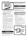
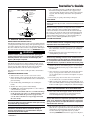
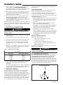
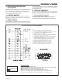
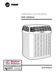
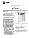
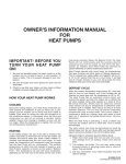
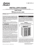
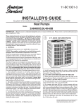
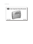
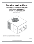
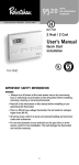
18-BC55D1-2
Installer’s Guide
Heat Pumps
4TWX6
ALL phases of this installation must comply with NATIONAL, STATE AND LOCAL CODES
IMPORTANT — This Document is customer property and is to remain with this unit. Please return to service information
pack upon completion of work.
These instructions do not cover all variations in
systems nor provide for every possible contingency to
be met in connection with installation. All phases of
this installation must comply with NATIONAL, STATE
AND LOCAL CODES. Should further information be
desired or should particular problems arise which are not
covered sufficiently for the purchaser’s purposes, the matter
should be referred to your installing dealer or local distributor.
A. GENERAL
!
UNIT CONTAINS R-410A REFRIGERANT!
R-410A OPERATING PRESSURE EXCEEDS THE
LIMIT OF R-22. PROPER SERVICE EQUIPMENT IS
REQUIRED. FAILURE TO USE PROPER SERVICE
TOOLS MAY RESULT IN EQUIPMENT DAMAGE OR
PERSONAL INJURY.
The following instructions cover 4TWX6 Heat Pump Units.
SERVICE
NOTICE:
These outdoor units may be used with indoor units
equipped with Thermostatic Expansion Valve only.
!
WARNING
CAUTION
USE ONLY R-410A REFRIGERANT AND
APPROVED POE COMPRESSOR OIL.
1
5 FT. ABOVE UNIT-UNRESTRICTED
These units use R-410A refrigerant which operates at 50 to
70% higher pressures than R-22. Use only R-410A approved
service equipment. Refrigerant cylinders are painted a “Rose”
color to indicate the type of refrigerant and may contain a
“dip” tube to allow for charging of liquid refrigerant into the
system. All R-410A systems use a POE oil that readily absorbs
moisture from the atmosphere. To limit this “hygroscopic”
action, the system should remain sealed whenever possible. Never break a vacuum with air and always change the
driers when opening the system for component replacement.
Check for transportation damage after unit is uncrated.
Report promptly, to the carrier, any damage found to the unit.
To determine the electrical power requirements of the unit,
refer to the nameplate of the unit. The electrical power
available must agree with that listed on the nameplate.
The Weathertron® Heat Pump has been designed and
manufactured to withstand and operate in severe winter
conditions. However, there are precautionary steps which
should be taken at the time of installation which will help
assure the efficient operation of the unit. It is recommended that these precautions be taken for units
being installed in areas where snow accumulation and
prolonged below freezing temperatures occur.
1. Units should be elevated 3 to 12 inches above the pad or
rooftop, depending on local weather. This additional
height will allow better drainage of snow and ice (melted
during defrost cycle) prior to its refreezing. This should
prevent a build-up of ice around the unit which occurs
when unit is not elevated. Insure that drain holes in
unit base pan are not obstructed preventing
draining of defrost water.
2. If possible, avoid locations that are likely to accumulate
snow drifts. If not possible, a snow drift barrier should be
installed around the unit to prevent a build-up of snow
on the sides of the unit and should be of sufficient
distance from the unit to prevent restriction of airflow to
and from the unit. Also allow for proper maintenance
space. The barrier should be constructed of materials
which will blend in with the building design.
3. Avoid locating the unit where condensation and freezing
of defrost vapor may annoy the customer. For instance,
Installer’s Guide
2
BASEPAN TAB REMOVAL
The indoor end of the recommended refrigerant line sets may
be straight or with a 90 degree bend, depending upon
situation requirements. This should be thoroughly checked
out before ordering refrigerant line sets.
The gas line must always be insulated.
!
CAUTION
In scroll compressor applications, dome temperatures may
be hot. Do not touch top of compressor, may cause minor
to severe burning.
The units are factory charged with the system charge
required when using fifteen (15) feet of connecting line. Unit
nameplate charge is the same.
installing the unit under a bedroom, kitchen, or picture
window may be annoying to the customer since condensate and fog will occur during the defrost cycle.
4. Avoid locating the unit under the eaves or other overhead structures as sizeable icicles may form and the unit
may be damaged by these falling icicles.
B. LOCATION AND PREPARATION
OF THE UNIT
Final refrigerant charge adjustment is necessary. Use
the Charging Charts in the outdoor unit Service Facts.
1. Determine the most practical way to run the lines.
2. Consider types of bends to be made and space limitations.
NOTE:
Large diameter tubing will be very difficult to rebend once it
has been shaped.
1. When removing unit from the pallet, notice the tabs on
the basepan. Remove tabs by cutting with a sharp tool as
shown above in Figure 2, and slide unit off of pallet.
3. Determine the best starting point for routing the
refrigerant tubing — INSIDE OR OUTSIDE THE
STRUCTURE.
2. The unit should be set on a level support pad at least as
large as the unit base pan, such as a concrete slab. If this
is not the application used please refer to application
bulletin “Trane APB2001-02”.
4. Provide a pull-thru hole of sufficient size to allow both
liquid and gas lines.
3. The support pad must NOT be in direct contact with any
structure. Unit must be positioned a minimum of 12" from
any wall or surrounding shrubbery to insure adequate
airflow. Clearance must be provided in front of control
box (access panels) and any other side requiring service
access to meet National Electrical Code. Also, the unit
location must be far enough away from any structure to
prevent excess roof run-off water from pouring directly
on the unit. Do not locate unit(s) close to bedroom(s).
4. The top discharge area must be unrestricted for at least
five (5) feet above the unit.
5. When the outdoor unit is mounted on a roof, be sure the
roof will support the unit’s weight. Properly selected
isolation is recommended to prevent transmission to the
building structure.
6. The maximum length of refrigerant lines from outdoor to
indoor unit should NOT exceed eighty (80) feet.
5. Be sure the tubing is of sufficient length.
6. Uncoil the tubing — do not kink or dent.
7. Route the tubing making all required bends and properly
secure the tubing before making connections.
8. To prevent a noise within the building structure due to
vibration transmission from the refrigerant lines, the
following precautions should be taken:
a. When the refrigerant lines have to be fastened to floor
joists or other framing in a structure, use isolation
type hangers.
b. Isolation hangers should also be used when refrigerant lines are run in stud spaces or enclosed ceilings.
c. Where the refrigerant lines run through a wall or sill,
they should be insulated and isolated.
d. Isolate the lines from all ductwork.
3
LIQUID LINE SERVICE VALVE
7. If outdoor unit is mounted above the air handler, maximum lift should not exceed twenty-five (25) feet (suction
line). If air handler is mounted above condensing unit,
maximum lift should not exceed twenty-five (25) feet (liquid line).
8. Locate and install indoor coil or air handler in accordance with instruction included with that unit.
C. INSTALLING REFRIGERANT LINES
!
CAUTION
If using existing refrigerant lines make certain that all joints
are brazed, not soldered.
Condensing units have provisions for braze connections.
Pressure taps are provided on the service valves of outdoor
unit for compressor suction and liquid pressures.
© 2005 American Standard Inc. All Rights Reserved
18-BC55D1-2
Installer’s Guide
4
GAS LINE SERVICE VALVE
CAP
1/4 TURN ONLY
COUNTERCLOCKWISE
FOR FULL OPEN
POSITION
7. Use a Dry Nitrogen Purge and Brazing Alloy without
flux when brazing the field line to the copper factory
connection. Flow dry nitrogen into either valve pressure
tap port, thru the tubing and out the other port while
brazing.
VALVE STEM
8. Braze using accepted good brazing techniques.
UNIT SIDE
OF VALVE
LEAK CHECK
IMPORTANT:
Replace pressure tap port valve core before attaching hoses for
evacuation.
PRESSURE TAP PORT
GAS LINE CONNECTION
CAP
BODY
COOLING
HEATING
CORE
D. SERVICE VALVE OPERATION
BRASS LIQUID LINE SERVICE VALVE
The Brass Liquid Line Service Valve is factory shipped in the
seated position to hold factory charge. The pressure tap service
port (when depressed) opens only to the field brazing side of
the valve when the valve is in the seated position. The liquid
line valve is not a back seating valve (see WARNING below).
!
WARNING
Extreme caution should be exercised when opening the
Liquid Line Service Valve. Turn valve stem counterclockwise only until the stem contacts the rolled edge. (See
Figure 3) No torque is required.
BRASS GAS LINE SERVICE VALVE
The Brass Gas Line Service Valve is shipped in the closed
position to hold the factory refrigerant charge. The pressure
tap service port (when depressed) opens only to the field
brazing side when the valve is in the closed position.
The Gas Line Service Valve is full open with a 1/4 turn. See
Figure 4.
BRAZING REFRIGERANT LINES
1. Remove lower access cover to access service valves.
2. Before brazing, remove plugs from external copper stub
tubes. Clean internal and external surfaces of stub tubes
prior to brazing.
3. Cut and fit tubing, minimizing the use of sharp 90°
bends.
4. Insulate the entire gas line and its fittings.
5. Do NOT allow uninsulated liquid line to come in direct
contact with bare gas line.
6. Precautions should be taken to avoid heat damage
to the pressure tap valve core during brazing. It is
recommended that the pressure tap port valve
core be removed and a wet rag wrapped around
the valve body.
NOTICE:
Use care to make sure that no moisture enters pressure tap
port, while wet rag is being used.
NOTICE:
Precautions should be taken to avoid heat damage to
basepan during brazing. It is recommended to keep the
flame directly off of the basepan.
18-BC55D1-2
After the brazing operation of refrigerant lines to both the
outdoor and indoor unit is completed, the field brazed
connections must be checked for leaks. Pressurize through
the service valve ports, the indoor unit and field refrigerant
lines with dry nitrogen to 350-400 psi. Use soap bubbles or
other leak-checking methods to see that all field joints are
leak-free! If not, release pressure; then repair!
SYSTEM EVACUATION
NOTE:
Since the outdoor unit has a refrigerant charge, the gas and
liquid line valves must remain closed.
1. Upon completion of leak check, evacuate the refrigerant
lines and indoor coil before opening the gas and liquid
line valves.
2. Attach appropriate hoses from manifold gauge to gas
and liquid line pressure taps.
NOTE:
Unnecessary switching of hoses can be avoided and complete evacuation of all lines leading to sealed system can
be accomplished with manifold center hose and connecting branch hose to a cylinder of R-410A and vacuum pump.
3. Attach center hose of manifold gauges to vacuum pump.
4. Evacuate until the micron gauge reads no higher than
350 microns.
5. Close off valve to vacuum pump and observe the micron
gauge. If gauge pressure rises above 500 microns in
one (1) minute, then evacuation is incomplete or system
has a leak.
6. If vacuum gauge does not rise above 500 microns in
one (1) minute, the evacuation should be complete.
7. With vacuum pump and micron gauge blanked off, open
valve on R-410A cylinder and charge refrigerant lines and
indoor coil with vapor to tank pressure of R-410A supply.
NOTE:
DO NOT VENT REFRIGERANT INTO THE ATMOSPHERE.
8. Close valve on R-410A supply cylinder. Close valves on
manifold gauge set and remove refrigerant charging
hoses from liquid and gas pressure tap ports.
NOTE:
A 3/16" Allen wrench is required to open liquid line service
valve. A 1/4" Open End or Adjustable wrench is required to
open gas line valve. A 3/4" Open End wrench is required to
take off the valve stem cap.
9. The liquid line shut-off valve can now be opened. Remove
shut-off valve cap. Fully insert hex wrench into the stem
and backout counterclockwise until valve stem just
touches rolled edge (approximately five [5] turns)
observing WARNING statement on page 2. See Figure 3.
3
Installer’s Guide
10. Replace liquid service pressure tap port cap and valve
stem cap. These caps MUST BE REPLACED to
prevent leaks. Replace valve stem and pressure tap cap
finger tight, then tighten an additional 1/6 turn.
11. The gas valve can now be opened. Open the gas valve by
removing the shut-off valve cap and turning the valve
stem 1/4 turn counterclockwise, using 1/4" Open End or
Adjustable wrench. See Figure 4.
12. The gas valve is now open for refrigerant flow. Replace
valve stem cap to prevent leaks. Again, these caps
MUST BE REPLACED to prevent leaks. Replace valve
stem and pressure tap cap finger tight, then tighten an
additional 1/6 turn. See Figure 4.
If refrigerant lines are longer than 15 feet and/or a different
size than recommended, it will be necessary to adjust system
refrigerant charge upon completion of installation. See unit
Service Facts.
E. ELECTRICAL CONNECTIONS
WARNING
When installing or servicing this equipment, ALWAYS
exercise basic safety precautions to avoid the possibility
of electric shock.
1. Power wiring and grounding of equipment must comply
with local codes.
2. Power supply must agree with equipment nameplate.
3. Install a separate disconnect switch at the outdoor unit.
4. Ground the outdoor unit per local code requirements.
5. Provide flexible electrical conduit whenever vibration
transmission may create a noise problem within the
structure.
6. The use of color coded low voltage wire is recommended
to simplify connections between the outdoor unit, the
thermostat and the indoor unit.
Table 1 — NEC Class II Control Wiring
FAULT IDENTIFICATION
A fault condition is indicated by the flashing light on the
defrost control inside the heat pump control box.
In normal operation, the defrost control light will flash once
each second. If the light is flashing more than once per
second or not at all, refer to the service manual for that unit.
PIN IDENTIFICATION (See Figure 5.)
1. TEST_COMMON (Shorting any of the other pins to this
pin causes the function of the other pin to be executed.
Leaving this pin open results in the normal mode of
operation.)
2. TST = Test (Shorting TEST_COMMON to this pin
speeds up all defrost board timings.)
3. FRC_DFT = Forced Defrost (Short TEST_COMMON to
this pin for two (2) seconds to initiate a forced defrost.
Remove the short after defrost initiates.)
4. LOW_FAN = Low speed Fan test mode (Short
TEST_COMMON to this pin to force the outdoor fan to
low speed. When the short is removed, the fan will go
to high speed for approximately 15 seconds and then
return to the speed it was running before the short
was applied.)
DEFROST CONTROL CHECKOUT
Normal operation requires:
a. LED on board flashing 1 time/second.
b. 24V AC between R & B
c. 24V AC between Y & B with unit operating
d. Defrost initiation when FRC_DFT pin is shorted to
TEST_COMMON pin.
If a defrost control problem is suspected, refer to the service
information in control box.
!
WIRE SIZE
MAX. WIRE LENGTH
18 AWG
150 FT
16 AWG
225 FT.
14 AWG
300 FT.
7. Table 1 defines maximum total length of low voltage
wiring from outdoor unit, to indoor unit, and to
thermostat.
8. Mount the indoor thermostat in accordance with instruction included with the thermostat. Wire per appropriate
hook-up diagram (included in these instructions).
G. COMPRESSOR START UP
After all electrical wiring is complete, SET THE THERMOSTAT SYSTEM SWITCH IN THE OFF POSITION SO
COMPRESSOR WILL NOT RUN, and apply power by
closing the system main disconnect switch. This will activate
the compressor sump heat (where used). Do not change the
Thermostat System Switch until power has been applied for
one (1) hour. Following this procedure will prevent potential
compressor overload trip at the initial start-up.
5
PIN IDENTIFICATION
FRC_DFT
F. DEFROST CONTROL
The demand defrost control measures heat pump outdoor
ambient temperature with a sensor located outside the
outdoor coil. A second sensor located on the outdoor coil is
used to measure the coil temperature. The difference between
the ambient and the colder coil temperature is the difference
or delta-T measurement. This delta-T measurement is
representative of the operating state and relative capacity of
the heat pump system. By measuring the change in delta-T,
we can determine the need for defrost. The coil sensor also
TST
24 VOLTS
4
WARNING
Do NOT connect 24 VAC to T1 (ODS-A) terminal. ODS-A
thermistor WILL BE BLOWN.
TEST_COMMON
!
serves to sense outdoor coil temperature for termination of
the defrost cycle.
LOW_FAN
18-BC55D1-2
Installer’s Guide
H. OPERATIONAL AND CHECKOUT
PROCEDURES
Final phases of this installation are the unit Operational and
Checkout Procedures which are found in this instruction on
page 8. To obtain proper performance, all units must be
operated and charge adjustments made in accordance with
procedures found in the Service Facts.
I. ELECTRIC HEATERS
Electric heaters, if used, are to be installed in the air handling device according to the instructions accompanying the
air handler and the heaters.
components, provisions are made for a field installed start kit
accessory. When adding an accessory, follow the instructions
provided with the kit.
K. OUTDOOR THERMOSTAT
An outdoor thermostat TAYSTAT250A may be field installed.
For data, see wiring diagram attached to unit and instruction
sheet packaged with outdoor thermostat.
L. SEACOAST SALT SHIELD
All units are shipped with a black Seacoast Salt Shield
attached to the access panel. Removal of the shield will
potentially shorten the life of the joints in the outdoor coil.
J. START CONTROL
Some models have quick start components which are factory
installed. For models that do not have factory installed start
TYPICAL FIELD HOOK-UP DIAGRAM
See
Note A
Notes:
1. Be sure power supply agrees with equipment nameplate.
2. Power wiring and grounding of equipment must comply with local codes.
3. Low voltage wiring to be No. 18 AWG minimum conductor.
4. ODT-B must be set lower than ODT-A.
5. If ODT-B is not used, connect A Jumper wire from W3 to W2. If ODT-A is
not used, connect a jumper wire from W2 to W1.
6. If electric heat does not have 3rd contactor (CH), connect a jumper wire
from W3 to W2. If electric heat does not have 2nd contactor (BH),
connect a jumper wire from W2 to W1.
7. X2 must be connected to variable speed air handler terminal W3, as
shown, for proper indoor air flow during the defrost cycle.
8. Be sure the jumper between R and BK is cut or removed.
9. With O and Y/Y2 energized, indoor fan is at 80% airflow.
10. With O, Y/Y2 and BK energized, indoor fan is at 100% airflow.
11. Connect only if used with applicable indoor thermostat.
1
AIR HANDLER
G
O
R
B W3 W2 W1
BK
T
Y Ylo
Jumper
See Note B
LEGEND
FACTORY WIRING
FIELD WIRING
18-BC55D1-2
REQUIRED WIRING
Refer to Field Hook-up Diagrams above.
4TWX6 units require 80% airflow with Y1 (first stage), 100% airflow with Y2 (second stage).
Note A - The installer must jumper at the LVTB “R” to “O”.
Note B - Cut/remove the factory installed “BK” jumper (See Figure 1).
Connect “Y1” from thermostat to “Y/Y2” at VS Airhandler to “Y1” at Outdoor Unit.
Connect “Y2” from thermostat to “BK” at VS Airhandler to “Y2” at Outdoor Unit.
5
Installer’s Guide
4TWX6 OUTLINE DRAWING
NOTE: ALL DIMENSIONS ARE IN MM (INCHES).
MODELS
BASE
A
B
1118 (44)
C
D
E
F
G
H
J
K
4TWX6024B
3
829 (32-5/8)
756 (29-3/4)
5/8
5/16
143 (5-5/8)
92 (3-5/8)
210 (8-1/4)
79 (3-1/8)
692 (27-1/4)
4TWX6036B
4
1165 (45-7/8) 946 (37-1/4)
870 (34-1/4)
3/4
3/8
152 (6)
98 (3-7/8)
219 (8-5/8)
86 (3-3/8)
730 (28-3/4)
4TWX6048B
4
1267 (49-7/8) 946 (37-1/4)
870 (34-1/4)
7/8
3/8
152 (6)
98 (3-7/8)
219 (8-5/8)
86 (3-3/8)
730 (28-3/4)
4TWX6060B
4
1267 (49-7/8) 946 (37-1/4)
870 (34-1/4)
7/8
3/8
152 (6)
98 (3-7/8)
219 (8-5/8)
86 (3-3/8)
730 (28-3/4)
From Dwg. 21D152635 Rev. 11
6
18-BC55D1-2
Installer’s Guide
MOUNTING HOLE LOCATION
NOTE: ALL DIMENSIONS ARE IN MM (INCHES).
NOTE: For model base size,
see table on page 6.
18-BC55D1-2
From Dwg. D152637 Rev. 1
7
Installer’s Guide
CHECKOUT PROCEDURE
After installation has been completed, it is recommended that the entire system be checked against the following list:
1. Refrigerant Line, Leak checked .................................. [ ]
8. Supply registers and return grilles open and
unobstructed ................................................................ [ ]
2. Suction Lines and Fittings properly insulated ........... [ ]
9. Return air filter installed ............................................ [ ]
3. Have all Refrigerant Lines been secured and
isolated properly? ........................................................ [ ]
10. Thermostat thermometer is accurate. Check
against a reliable thermometer. Adjust per
instructions with thermostat ...................................... [ ]
4. Have passages through masonry been sealed?
If mortar is used, prevent mortar from coming
into direct contact with copper tubing ........................ [ ]
5. Verify tightness of all electrical connects ................... [ ]
11. Is correct speed tap being used?
(Indoor blower motor) .................................................. [ ]
6. Observe outdoor fan during on cycle for clearance
and smooth operation .................................................. [ ]
12. Operate complete system in each mode to
insure safe operation ................................................... [ ]
7. Indoor coil drain line drains freely. Pour water
into drain pan .............................................................. [ ]
TROUBLESHOOTING CHART — WHAT TO CHECK
.
DEF
OL
NTR DEF.
CO
Y
ST RELA ING
RO
K
T
D E F RO S
LEA
E
DEF ALVE ECTIV
V
G
CK
DEF
CHE OIL LEAKIN
C
S
SOV SOV TION
IC
S T R L OW
. RE AIRF
. CIR I.D. RHEAT
R E F R E S.
E
SUP OPEN
CK
N
STU ATIO
TXV IRCUL OW
L
REC AIRF S
.D.
LE
. AIR
O.D ES. O NSAB D
R
N D E L OA
NCO AP.
NO E EV ARGE
IV RCH E
ESS
E
G
EXC EF. OV CHAR .
R
DER OMP
. UN T C
REF ICIEN SSOR
E
FF
INE OMPR USE
F
C
CK
IL
AG E
STU VOLT R CO
O
LOW TACT STAT
O
N
CO HERM ER
M
T
OR G
NSF
IRIN
TRA
O L AG E W C T S
A
NTR
LT
CO W VO CONT AY
R
EL
LO
CTO
TR
NTA STAR CITOR
CO
A
CAP ITOR
C
RT
STA CAPA IOL
RUN SOR
RES IRING
MP
CO AGE W PLY
OLT
SUP
H V WER ODE
PO CK M
CHE
TO
AT
*
HIG
WH
SYSTEM FAULTS
REFRIGERANT CIRCUIT
P
P
C
H
C
H
C
H
C
H
C
H
C
H
C
H
C
H
Head Pressure Too High
Head Pressure Too Low
Suction Pressure Too High
Suction Pressure Too Low
Liquid Refrig. Floodback (TXV)
Liquid Refrig. Floodback
(Cap. Tube)
I.D. Coil Frosting
Compressor Runs
Inadequate or No Cooling/Htg
ELECTRICAL
Compressor & O.D. Fan
Won’t Start
Compressor Will Not Start
But O.D. Fan Runs
O.D. Fan Won’t Start
Compressor Hums But Won’t Start
Compressor Cycles on IOL
I.D. Blower Won’t Start
C
H
C
H
C
H
C
H
C
H
C
H
S
S
S
S
P
P
S
S
P
S
P
S
S
P
P
P
P
P
P
S
S
S
S
S
S
S
S
P
S
S
S
S
S
S
P
P
S
S
S
S
P
P
P
P
S
S
S
P
P
P
P
P
P
P
P
P
P
P
P
P
P
P
P
P
S
S
S
S
S
S
P
P
P
P
P
P
P
P
S
S
S
S
S
S
S
S
S
S
S
S
P
P
S
S
P
P
S
S
P
P
S
S
P
P
S
S
S
S
S
S
P
P
P
S
S
P
S
S
P
P
S
S
P
S
S
S
S
S
S
S
S
P
P
P
P
S
S
S
S
S
S
S
S
P
P
P
P
S
S
P
P
S
S
P
P
S
S
S
S
S
S
S
S
S
DEFROST
C
H
C
H
C
H
Unit Won’t Initiate Defrost
Defrost Terminates on Time
Unit Icing Up
C - Cooling
H - Heating
P - Primary Causes
P
P
S - Secondary Causes
Literature Order Number
P
P
P
P
S
S
S
P
P
* - 3 Phase Only
P.I. 02/05
File Number
Supersedes
Stocking Location
Trane
A business of
American Standard Companies
www.trane.com
Trane has a policy of continuous product and product data improvement and it reserves the right to change
design and specifications without notice.