1
SECTION 7 - LIFT SYSTEM
7.1 MANUAL LIFT
5. Reassemble the locator casting and mount to the
frame.
6. Put the lift lever assembly on the shaft so as to
align with the key. Use a soft hammer to drive in
place while holding down on the push rod.
7. Install the set screw and tighten the jam nut.
2
1
7.2 ELECTRIC/HYDRAULIC PUMP
1
3
2
4
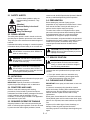
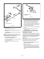
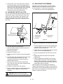
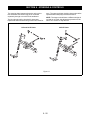
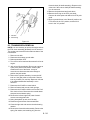
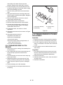
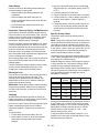
1. Lift Lever Shaft
2. Lift Lever Assembly
4
3. Lever Pawl
4. Locator Casting
5
Figure 12
P J0230
Disassembly
1. Remove the set screw in the lift lever assembly.
2. Apply liquid wrench to the shaft through the hole
where the pawl is positioned.
3. Loosen the two bolts holding the locator casting
and remove.
3
4. Disassemble the lift lever assembly by removing
the grip and rotate the push rod counterclockwise
to disengage the pawl.
1.
2.
3.
4.
5. Remove the key and the snap ring from the shaft.
6. Using a punch and hammer, drive the pivot
bushing outward from the frame.
7. Slide the lift lever shaft weldment to the left. Lift up
on the right end and pull from the frame.
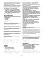
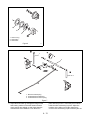
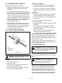
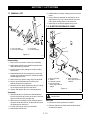
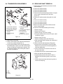
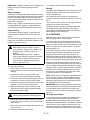
Motor Assembly
Adapter
Hydraulic Cylinder
Fluid Flows Both
Ways, High Pressure,
400 psi
5. Fluid Flows both
Ways, High Pressure,
1000 psi
Figure 13
8. Inspect and replace all worn or damaged parts.
PJ0030
Assembly
1. Slide the left end of the lift lever shaft weldment
into the frame hole and move to the left. Lower the
right end and slide into the right hole.
2. Slide new pivot bushings on the shaft and start in
the holes. Slide the lift lever on the shaft and drive
the bushings into the frame.
3. Put the snap ring on the key in the shaft.
CAUTION: Disconnect negative battery
terminal first.
Removal
1. Disconnect black ground wire at frame.
2. Remove switch from dash; leave the three leads
connected to switch.
4. Reassemble the lift lever.
7 - 21