1
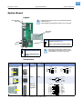
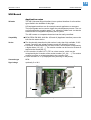
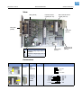
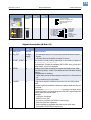
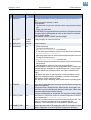
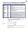
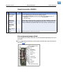
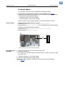
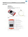
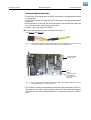
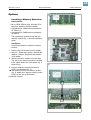
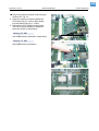
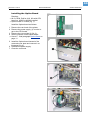
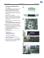
03/10 Rev. 5.04-01 SERVICE MANUAL 64-xx Gen. 2 – DPM Gen. 2 – ALX 92x Gen. 2 Service Electronics Handling boards ............................................ 2 ESD protection .......................................... 2 Handling .................................................... 2 CPU Boards .................................................. 3 Layout without Ethernet ............................ 3 Layout with Ethernet ................................. 4 Connectors ................................................ 5 Output stage board ....................................... 9 Important Notes ......................................... 9 Layout / Connecting .................................. 9 Connectors .............................................. 10 Option Board ............................................... 11 Layout ..................................................... 11 Connectors .............................................. 11 USI Board ................................................... 12 Application notes ..................................... 12 View ........................................................ 13 Connectors .............................................. 13 Signal description (D-Sub 15) ................. 14 Pin assignment internal inputs (CN 300) . 16 Signal description (CN300) ..................... 17 Pin assignment jumper block .................. 17 Block diagram ......................................... 18 Circuit diagrams for signal inputs ............ 19 Circuit diagrams for signal outputs .......... 20 Firmware update ..................................... 22 USI testbox ................................................. 23 Application ............................................... 23 View ........................................................ 23 Connecting the test box .......................... 24 Operation ................................................ 25 Diagram of a USI input ............................ 26 Display 64-xx ...............................................27 Layout ......................................................27 Connector ................................................27 Display DPM/ALX ........................................28 Layout ......................................................28 Connector ................................................28 Power Supplies ...........................................29 Application Notes .....................................29 Retrofitting the ME500 .............................29 NT400 (A1680) ........................................30 ME500 .....................................................31 HME .........................................................32 Printhead Voltages HME & Standard ......33 Characteristics HME power supply ..........34 Settings .......................................................35 Sensor setting ..........................................35 Sensor test ..................................................38 General notes ..........................................38 Sensors on the CPU board (64-xx) ..........39 Sensors on the CPU board (DPM/ALX) ...40 Value table for sensor 0.12 (printhead temp.) .....................................40 Sensors on the output stage boards (64-xx) ......................................................41 Sensors on the output stage boards (ALX/DPM) ...............................................41 Options ........................................................42 Installing a Memory Extension .................42 Installing the Option Board ......................44 Installing a Realtime Clock ......................45 Attaching locking clips for flat strap plugs 46 Index ............................................................48 2 03/10 Rev. 5.04-01 SERVICE MANUAL Service Electronics 64-xx Gen. 2 – DPM Gen. 2 – ALX 92x Gen. 2 Handling boards ESD protection All the boards described in the following are fitted, among other things, with large-scale integrated circuits. Voltage impulses caused by static charging from people or objects can easily destroy the circuits. When handling boards, ensure that the electronics cannot be damaged by static charging or discharging. ¯ CAUTION! Place the printer on an earthed underlay before opening it. ¯ CAUTION! Earth your body with an ESD protective armband or by using another suitable means. If suitable ESD protection is not available, touch an earthed object, e.g. a radiator, before touching a board. ¯ CAUTION! Only place boards on an earthed underlay. Handling The conductor lines on modern multilayer boards are very thin. Bending the boards can therefore easily break the conductor lines. ¯ CAUTION! Avoid bending the boards. ¯ CAUTION! Avoid using excessive force when removing and installing the boards. 3 03/10 Rev. 5.04-01 SERVICE MANUAL Service Electronics 64-xx Gen. 2 – DPM Gen. 2 – ALX 92x Gen. 2 CPU Boards JP301 Function Boot from U303 BootPROM Boot from system flash (default) Layout without Ethernet JP502 Function /503 +5V at Centronics pin 35 + 5V at Centronics pin 18 Default Sockel für 8bit Boot-PROM (U303) SO-DIMM 144 socket for memory extension (U201) CAUTION - Only for production purposes! JTAG interface (CN402) RTC socket (U701) Power supply USI board (CN1301) (CN1005) JP1101/ Function 1102 Constant LED current at dispensing edge sensor Constant LED current at Ø-sensor Disp.-Rewinder Pulsed LED current at dispensing edge sensor & at Ø-sensor Disp.-Rewinder Display Data cable peripheral (CN902) (I2C bus) (CN1003) Sensor dispensing edge (CN1101) Ø-sensor dispenser rewinder (DDS) (CN1102) CF card slot (CN801) Feed roller sensor (DPM/PEM/ALX=TS, 64-xx Dispenser=DTS) (CN1103) Material end sensor (MS) (CN1104) Punch sensor (PS) (CN1105) Reflex sensor (RS) (CN1106) Fullsize sensor (FSS) (CN1107) Centronics (CN501) Singlestart sensor (SSS) (CN1108) Cover sensor (COS) (CN1109) Power supply (CN1004) Internal scaner (CN1006) RS232 (CN601) Motor output stage (I2C bus) (CN1001) Option board (CN602) JP601 Function /602 RS422/485 termination: RxD RS422/485 termination: TxD RS232, no RS422/485 termination (default) CAUTION - Only for production purposes! H8-PRG-Adapter (CN1002) Printhead (CN901) JP102 Function 1-2 8bit boot bus width (for U303 Boot-PROM) 2-3 CAUTION - Line termination in RS485-mode: 2-wire-interface: close either JP601 or JP602! 4-wire-interface: close JP601 and JP602! 16bit boot bus width (default) L CAUTION Only for production purposes! JP1004 Function H8: RX1 RS232 level H8: RX1 TTL level (default) 4 03/10 Rev. 5.04-01 SERVICE MANUAL Service Electronics 64-xx Gen. 2 – DPM Gen. 2 – ALX 92x Gen. 2 Layout with Ethernet JP502 Function /503 +5V at Centronics pin 35 + 5V at Centronics pin 18 Default JP301 Function Boot from U303 BootPROM Boot from system flash (default) Sockel für 8bit Boot-PROM (U303) SO-DIMM 144 socket for memory extension (U201) CAUTION - Only for production purposes! JTAG interface (CN402) RTC socket (U701) Power supply USI board (CN1301) (CN1005) JP1101/ Function 1102 Constant LED current at dispensing edge sensor Constant LED current at Ø-sensor Disp.-Rewinder Pulsed LED current at dispensing edge sensor & at Ø-sensor Disp.-Rewinder Display Data cable peripheral (CN902) (I2C bus) (CN1003) Sensor dispensing edge (CN1101) Ø-sensor dispenser rewinder (DDS) (CN1102) CF card slot (CN801) Feed roller sensor (DPM/PEM/ALX=TS, 64-xx Dispenser=DTS) (CN1103) Material end sensor (MS) (CN1104) Ethernet 10/100 Base T (CN1501) Punch sensor (PS) (CN1105) Reflex sensor (RS) (CN1106) Fullsize sensor (FSS) (CN1107) Centronics (CN501) Singlestart sensor (SSS) (CN1108) Cover sensor (COS) (CN1109) Power supply (CN1004) Internal scaner (CN1006) RS232 (CN601) Motor output stage (I2C bus) (CN1001) Option board (CN602) JP601 Function /602 RS422/485 termination: RxD RS422/485 termination: TxD RS232, no RS422/485 termination (default) CAUTION - Only for production purposes! H8-PRG-Adapter (CN1002) Printhead (CN901) JP102 Function 1-2 8bit boot bus width (for U303 Boot-PROM) 2-3 CAUTION - Line termination in RS485-mode: 2-wire-interface: close either JP601 or JP602! 4-wire-interface: close JP601 and JP602! 16bit boot bus width (default) CAUTION - Only for production purposes! JP1004 Function H8: RX1 RS232 level H8: RX1 TTL level (default) 5 03/10 Rev. 5.04-01 SERVICE MANUAL Service Electronics 64-xx Gen. 2 – DPM Gen. 2 – ALX 92x Gen. 2 Connectors Picture I2C Motordr. Bus Comp. Type on Diagram board CN1001 3M 25146002 PRG Adapter CN1002 3M 25146002 I2C-Bus CN1003 PANCON MLSS 100-04 Power supply CN1004 PANCON MLSS 100-09 USI CN1005 3M 25146002 Type at cable Pin assignment on board 1 - CLK_0 3 - CLK_2 5 - CLK_4 7 - CLK_6 9 - SCL 11 - EX_RES\ 13 - n.c. 1 - VCC 5V 3 - n.c. 5 - EX_RES\ 7 - SCL 9 - SDA 11 - VCC 5V 13 - TX1_232 2 - CLK_1 4 - CLK_3 6 - CLK_5 8 - CLK_7 10 - SDA 12 - H8_IRQ4\ 14 - GND 2 - MD2 4 - RX1 6 -TX1 810 - PRGRES\ 12 - GND 14 - RX1_232 1 - SDA 2 - SCL 3 - EX_RES\ 4 - CLK_7 1 - H8_NMI 2 - ICS 3 - PS_ISK 4 - PS_I/O 5 - ASENSOR_0 6 - KA 7 - KD 8 - KS 9 - n.c. 2 - EX_RES\ 4 - AI_IRQ\ 6 - H8_IRQ4\ 8 - SCL 10 - SDA 12 - TX1 14 - APFS 1 - VCC 5V 3 - VCC 5V 5 - VCC 5V 7 - GND 9 - GND 11 - RX1 13 - GND Scanner Tab. 1: CN1006 Hirose DF1124DP-2V Connector description CPU board 2 - GND 4 - n.c. 6 - H8_PA0 8 - n.c. 10 - GND 12 - n.c. 14 - n.c. 16 - n.c. 18 - n.c. 20 - n.c. 22 - n.c. 24 - n.c. 1 - VCC 5V 3 - FRAME 1 5 - n.c. 7 - n.c. 9 - H8_IRQ5\ 11 - H8_PB84 13 - n.c. 15 - R1 IN 17 - T1 0UT 19 - n.c. 21 - n.c. 23 - GND 6 03/10 Rev. 5.04-01 SERVICE MANUAL Service Electronics 64-xx Gen. 2 – DPM Gen. 2 – ALX 92x Gen. 2 Picture Comp. Type on Type at Diagram board cable Sensor dispensing CN1101 PANCON edge MLSS 100-04 Ø-sens. rewinder Sens. feed roller Material end S. Punch Sensor Reflex Sensor Fullsize Sensor Singlestart sens. CN1102 PANCON MLSS 100-04 CN1103 PANCON MLSS 100-04 CN1104 PANCON MLSS 100-04 CN1105 PANCON MLSS 100-04 CN1106 PANCON MLSS 100-04 CN1107 PANCON MLSS 100-04 CN1108 PANCON MLSS 100-04 Tab. 1: (Continued) Connector description CPU board Pin assignment on board 1 - Anode 2 - Cathode 3 - Collector 4 - Emitter 1 - Anode 2 - Cathode 3 - Collector 4 - Emitter 1 - Anode 2 - Cathode 3 - Collector 4 - Emitter 1 - Anode 2 - Cathode 3 - Collector 4 - Emitter 1 - Anode 2 - Cathode 3 - Collector 4 - Emitter 1 - Anode 2 - Cathode 3 - Collector 4 - Emitter 1 - Anode 2 - Cathode 3 - Collector 4 - Emitter 1 - Anode 2 - Cathode 3 - Collector 4 - Emitter 7 03/10 Rev. 5.04-01 SERVICE MANUAL Service Electronics 64-xx Gen. 2 – DPM Gen. 2 – ALX 92x Gen. 2 Picture Cover switch Comp. Type on Type at Diagram board cable CN1109 PANCON MLSS 100-02 Ethernet CN1501 RJ 45 Centronics CN501 IEEE 1284 B 36pin RS232/422/485 CN601 DSub9-F Pin assignment on board 1 - Signal cover switch 2 - GND 1 - TD+ 2 - TD3 - RD+ 4 - Termination 5 - Termination 6 - RD7 - Termination 8 - Termination 36 - SELECT_IN\ 35 - VCC 5V (JP503 geschl.) 34 - n.c. 33 - GND 32 - FAULT\ 31 - INIT\ 30 - GND 29 - GND 28 - GND 27 - GND 26 - GND 25 - GND 24 - GND 23 - GND 22 - GND 21 - GND 20 - GND 19 - GND 18 - VCC 5V (JP502 geschl.) 17 - n.c. 16 - n.c. 15 - n.c. 14 - AUTO_FEED\ 13 - SELECT 12 - PAPER END 11 - BUSY\ 10 - ACK\ 9 - LPT_D7 8 - LPT_D6 7 - LPT_D5 6 - LPT_D4 5 - LPT_D3 4 - LPT_D2 3 - LPT_D1 2 - LPT_D0 1 - STROBE\ RS232 9 - (RI) 8 - CTS 7 - RTS 6 - (DSR) RS422/485 5 - GND 4 - (DTR) 3 - TxD 2 - RxD 1 - (CD) 9 - n.c. 8 - Tx+ 7 - Rx+ 6 - n.c. L CAUTION! RS232 pin assignment looked at from „PC point of view“! (Printer = DCE) Option board CN602 3M 25206002 Tab. 1: (Continued) Connector description CPU board 20 - RESET 18 - VCC 3V3 16 - KBDCLK 14 - ON_2 12 - RS232_2\ 10 - GND 8 - RTS_2\ 6 - DTR_2\ 4 - DSR_2\ 2 - SOUT_2 19 - GND 17 - KBDDAT 15 - DXEN_2 13 - RXEN_2 11 - RI_2\ 9 - VCC 5V 7 - CTS_2\ 5 - GND 3 - SIN_2 1 - DCD_2\ 5 - GND 4 - n.c. 3 - Rx2 - Tx1 - n.c. 8 03/10 Rev. 5.04-01 SERVICE MANUAL Service Electronics 64-xx Gen. 2 – DPM Gen. 2 – ALX 92x Gen. 2 Picture Printhead Display Comp. Type on Diagram board CN901 3M 25206002 CN902 Type at cable 3M 25206002 Tab. 1: (Continued) Connector description CPU board Pin assignment on board 1 - HVCC 3 - GND 5 - HDATA 1 7 - HCLK 9 - HLCH 11 - HBE 0 13 - HSTB 2/HDATA 3 15 - HCONT 2 17 - HCONT 4 19 - HDATA 4 1 - ON/OFF\ 3 - CUT\ 5 - FEED\ 7 - PROG\ 9-E 11 - RS 13 - R_W\ 15 - ERROR 17 - RESET 19 - GND 2 - HVCC 4 - GND 6 - HDATA 2 8 - GND 10 - GND 12 - HSTB 1 14 - HCONT 1 16 - HCONT 3 18 - HCONT 5 20 - HTHM 1 2 - D0 4 - D1 6 - D2 8 - D3 10 - D4 12 - D5 14 - D6 16 - D7 18 - RESET 20 - GND 9 03/10 Rev. 5.04-01 SERVICE MANUAL Service Electronics 64-xx Gen. 2 – DPM Gen. 2 – ALX 92x Gen. 2 Output stage board Important Notes ¯ Please keep in mind the following points, when you replace or check an out• • put stage board: PIC version: The PIC must carry a label with the writing "M04A V3 C73"! Jumper setting: The jumper setting must match the motor which is ought to be driven by the output stage! Layout / Connecting Jumper J6 J1 J7 J6 J1 J7 J6 J1 J7 J6 J1 J7 J6 J1 J7 Function Options motor (e.g. cutter, ext. rewinder, dispenser: release motor) Printhead motor Sensor (J4) Optional: additional sensor (J8) Ribbon motor Feed motor Motor (J3) Dispenser motor ALX 92x / 64xx Dispenser) Power supply (J12) Output stage for Feed motor Ribbon motor Printhead motor Options motor Dispenser motor [1] Control lines, coming from the CPU board (J2) Marker at motor cable FM RM HM OM WM Marker at sensor cable no sensor RS HS OS no sensor By setting the jumpers, you prepare the output stage board for application with the motor you intend to drive (tab. left side). Connecting the cables: Identify the right motor or sensor cable by its marker on the cable sleeve (tab. below). 10 03/10 Rev. 5.04-01 SERVICE MANUAL Service Electronics 64-xx Gen. 2 – DPM Gen. 2 – ALX 92x Gen. 2 Connectors Picture Comp. Type on board Diagr. J4 PANCON MLAS 100-04 Type at cable Pin assignment on board AMP 643813-4 oder AUK MK-04H 1-A 2 - K (GND) 3-C 4 - E (GND) J3 PANCON MLAS 100-04 AMP 643813-4 oder AUK MK-04H 1-A 2 - A\ M J2 Wieson 2120-14RS5 3-B 4 - B\ 11 - Reset\ 9 - I2C-SCL 1 - Clock 0 MOLEX 70450 Version b 10 - I2C-SDA 14 - GND J12 Tab. 2: AMP 640389-6 Connectors on the output stage board. AMP 0-644465-6 MTA 156 18 AWG 1 - 5V 2 - GND 3 - n.c. 4 - GND 5 - 38..54V 6 - GND 11 03/10 Rev. 5.04-01 SERVICE MANUAL Service Electronics 64-xx Gen. 2 – DPM Gen. 2 – ALX 92x Gen. 2 Option Board Layout PS/2 keyboard (CN103) L CAUTION! The maximum output current of the PS/2 interface is 500mA at 25°C! A self-resetting fuse interrupts the current in case of over load. CPU board (CN104) JP102 Function RS422/485 termination: TxD COM2 (CN101) RS232, no RS422/485 termination (default) JP101 Function RS422/485 termination: RxD L CAUTION! Line termination in RS485-mode: 2-wire-interface: close either JP101 or JP102! 4-wire-interface: close JP101 and JP102! RS232, no RS422/485 term. (default) Connectors Picture RS232/422/485 Comp. Diagr. CN101 Type on Type at Pin assignment on board board cable RS232 DSub9-F DSub9-M 5 - GND 4 - DTR 3 - RxD 2 - TxD 1 - DCD 9 - n.c. 8 - RTS 7 - CTS 6 - DSR Tastatur CN 103 PS/2 PS/2 2 - n.c. 1 - Data CPU-Platine CN104 Fig. 2: Kabel ist an Platine angelötet Connectors on the option board 2 - SOUT 2 4 - n.c. 6 - n.c. 8 - RTS 2\ 10 - GND 12 - RS232_2\ 14 - ON_2 16 - KBDCLK 18 - n.c. 20 - RESET RS422/485 9 - n.c. 8 - Tx+ 7 - Rx+ 6 - n.c. 4 - + 5V 6 - n.c. 3 - GND 5 - Clock 1 - n.c. 3 - SIN 2 5 - GND 7 - CTS_2\ 9 - VCC 5V 11 - n.c. 13 - RXEN 2 15 - DXEN 2 17 - KBDDAT 19 - GND 5 - GND 4 - n.c. 3 - Rx2 - Tx1 - n.c. 12 03/10 Rev. 5.04-01 SERVICE MANUAL Service Electronics 64-xx Gen. 2 – DPM Gen. 2 – ALX 92x Gen. 2 USI Board Application notes Utilization The USI (Universal Signal Interface) is an optional interface for all machine types listed in the headline of this page. USI-equipped machines can for example control applicators or scanners. The input signals can be used to trigger the print-dispense-process. The output lines signal the operating status - e.g. material or ribbon end - so that the machine can be integrated completely into a system. The USI comes on a separate board and can be easily retrofitted. Compatibility ¯ DPM, PEM, PM 3000, ALX 92x: USI and AI (Applicator Interface) can not be built into the same device. Version ¯ The functionality described in this section is only then fully available, if USI board, Controller and printer firmware match the following versions: y USI board: At least A2345-04 or a later version, which can be recognized by a higher index (-05, -06, …). The version number can be found on a label attached to the board [3B, C]. y USI controller: At least V2-T1-F873 or a later version, which can be recognized by the V-section of the version number (V3-, V4-, …). The version number is written on a label attached to the controller [3A]. y Printer firmware: 4.12 (is displayed after powering on the printer). Connection type NPN Signal voltage optionally 5 or 24 V A C [3] At those places, you find the version designations on the USI board. B 13 03/10 Rev. 5.04-01 SERVICE MANUAL Service Electronics 64-xx Gen. 2 – DPM Gen. 2 – ALX 92x Gen. 2 View SPS (optional) USI board version number (here: -04) Micro controller version number (here: V2) USI signals (VB200) CPU board (CN101) JP8 Power supply (CN100) Function 5V internal voltage supply active on Pin2/DB-15 5V external voltage supply on Pin 2/ DB-15 Connector for internal USI inputs (CN 300) Connectors Picture Comp. Diagr. CN100 CN101 Tab. 3: Connectors on the USI board. Type on Type at board cable AMP 640457-4 Cable is soldered to the board Pin assignment on board 1 - EXT 24V 2 - n.c. 3 - n.c. 4 - EXT GND 2 - EX_RES\ 4 - AI_IRQ\ 6 - H8_IRQ4\ 8 - SCL 10 - SDA 12 - n.c. 14 - APSF 1 - VCC +5V 3 - VCC +5V 5 - VCC +5V 7 - GND 9 - GND 11 - n. c. 13 - GND 14 03/10 Rev. 5.04-01 SERVICE MANUAL Service Electronics 64-xx Gen. 2 – DPM Gen. 2 – ALX 92x Gen. 2 Picture Comp. Diagr. CN300 Type on board Type at cable Pin assignment on board 1 - OD control material 2 - Applicator homeposition error 3 - Applicator touchdown error 4 - SPS ready/error 5 - GND VB200 15 - MACHINE STATUS\ 14 - DATA_RDY\ 13 - RIBBON_OUT\ 12 - MEDIA_OUT\ 11 - PRINT_END\ 10 - ERROR\ 9 - WARNING 8 - GND_EXT 7 - 24V_EXT 6 - REPRINT\ 5 - PAUSE\ 4 - FEED\ 3 - START_PRINT\ 2 - 5V_EXT 1 - GND_EXT Tab. 3: (Continued) Connectors on the USI board. Signal description (D-Sub 15) Pin Signal Signal type Ground 1 GND_EXT 2 5V_EXT 3 START_PRINT\ In 4 FEED\ In 5 PAUSE\ In Tab. 4: Voltage supply Function Ground contact JP8 connected: Internal 5 V source can be used via the wire for external sensors. • JP8 clear: Wire can be used for an external 5 V source. The machine starts printing depending on the setting of parameter DP INTERFACE > Start print mode. Preconditions: Printjob is available (DATA RDY\ low), printer is in online mode, no error messages. Feeding of the label material as long as the signal is low. Minimum feed quantity: 1 label. The display shows „USI feed“ during feeding. Preconditions for feeding: • Offline mode, printing has been stopped or the printer is in USI-paused mode. • Online mode and no print job loaded. A high-low-transition switches the printer into the USI-paused mode. A further high-low-transition switches the printer back into the online mode. If parameter DP INTERFACE > Start print mode is set to Level high active or Level low active, any activating of the PAUSE\ signal stops the printing after the current label. Features: • „USI Pause“ is displayed • ERROR\ is activ (low) • If a print job is available: DATA RDY\ is inactive (high) • Start print signals are suppressed • Reprint requests are proceeded after switching into online mode. • Precondition: START PRINT\ inactive (high). • Signal designations and functions of the USI interface. 15 03/10 Rev. 5.04-01 SERVICE MANUAL Service Electronics 64-xx Gen. 2 – DPM Gen. 2 – ALX 92x Gen. 2 Pin Signal Signal type In 6 REPRINT\ 7 24V_EXT 8 GND_EXT Voltage supply Ground 9 WARNING Out 10 ERROR\ Out 11 PRINT_END\ Out 11 HOME_POS\ Out Function The last printed label is being reprinted as long as REPRINT\ is low. Minimum reprint quantity: 1 label. Preconditions: • The label which is ought to be reprinted, must be ready printed and dispensed. • Printer is in online mode. If a REPRINT\ is triggered while the printer is in USI-pause mode, the reprint will be proceeded as soon as the printer is switched back in online mode. Precondition: START PRINT\ inactive (high). Voltage supply for external sensors Ground contact Ribbon low warning: The signal is activated (high), if a) DP INTERFACE > Ribbon signal = activated and b) The ribbon stock is below the threshold value, which is set in parameter SYSTEM PARAMETER > Ribbon warning. After changing the ribbon roll, the signal will be inactivated after a short time. • The signal is activated (high), if a) DP INTERFACE > Material signal = activated and b) The label material stock is below the threshold, which is set by positioning the light barrier After changing the material roll, the signal will be inactivated. The WARNING output is only then inactivated (low), if ribbon and material both are available in a sufficient amount. If one of both rolls falls below the threshold value, the output switches activ (high). In practice, the more or less eccentric running material roll will trigger the material warning repeatedly, until the roll diameter falls below a certain tolerance zone. This signal is only a warning, what means that the printing goes on. This output is activated (low) during every status which keeps the printer from printing: USI-pause mode, stopped mode, offline mode, hood open, material end, no punch recognized, pressure roller open, ribbon end and other failures which avoid printing. During the initialization of the printer, the output is inactive (high)! The manner in which this output is switched depends on the setting of parameter DP INTERFACE > End print mode. Difference to older versions of printer firmware (below 2.46): The output is now also activated as long as labels are fed. Limitation: This functionality is not available in Batch mode! Printer operation with LTSI applicator (with PLC version 5.0 and higher): Applicator is in home position (upper limit position) • Tab. 4: (Continued) Signal designations and functions of the USI interface. 16 03/10 Rev. 5.04-01 SERVICE MANUAL Service Electronics 64-xx Gen. 2 – DPM Gen. 2 – ALX 92x Gen. 2 Pin Signal Signal type Out 12 MEDIA_OUT\ 13 RIBBON_OUT\ Out 14 DATA_RDY\ Out 15 MACHINE STATUS\ Out Function Low in case of material end. Additionally activated are: • ERROR\ • MACHINE STATUS\ Low in case of ribbon end. Additionally activated are: • ERROR\ • MACHINE STATUS\ This signal is activated (low), if the printer has finished image processing and is ready to start printing. The signal is inactivated, if • the print job is done, or • the printer is switched to stopped mode, offline mode or USI-pause mode. This output is activated (low), if the printing has been interrupted by a disturbance or an error. Examples are: Pressure roll open, hood open, ribbon- or material end error, start print error or another fault that avoids printing. The output is also activated during the initialization of the printer. In comparison to ERROR\, MACHINE STATUS\ is not low if the printer has been switched to offline or pause mode. Printer operation with LTSI applicator (with PLC version 5.0 and higher): No function Tab. 4: (Continued) Signal designations and functions of the USI interface. Pin assignment internal inputs (CN 300) The following parameter settings are required to make the internal inputs useable: PLC For usage with PLC: • • OD sensor DP INTERFACE > Interface type = USI Applicator DP INTERFACE > Internal inputs = Enabled For useage with „OD sensor material“: • • DP INTERFACE > Material signal = Enabled DP INTERFACE > Internal inputs = Enabled If PLC and „OD sensor material“ are ought to be used, all three parameter settings have to be done. ¯ To all four inputs applies: The input is inactivated if it is connected to ground potential! 17 03/10 Rev. 5.04-01 SERVICE MANUAL Service Electronics 64-xx Gen. 2 – DPM Gen. 2 – ALX 92x Gen. 2 Signal description (CN300) Pin Signal 1 OD control material 2 Applicator fault home position Applicator fault touch down PLC ready / fault GND 3 4 5 Signal type In Function To be applied to the OD control material option. The signal WARNING at pin 9 of the DB 15 is switched activ, if • Parameter DP INTERFACE > Material Signal = Activated and • the input is high If one of the inputs is high or makes a low-high-transition, the appropriate status message is displayed at the printer. Additionally, the outputs ERROR\ and MACHINE STATUS\ will be activated (low). In In In Ground GND potential of the internal inputs [Tab. 5] Signal designations and functions of the internal inputs Pin assignment jumper block Each signal of the D-Sub connector can be interrupted separately at the jumper block. ¯ The voltage and ground wires are through-connected and cannot be interrupted (see Fig. 4)! GND MACHINE STATUS\ REPRINT\ 24 V DATA RDY\ RIBBON OUT\ PAUSE\ MEDIA OUT\ FEED\ PRINT END\ START PRINT\ 5V GND WARNING ERROR\ APPLICATOR MODE [4] Pin assignment jumper block 18 03/10 Rev. 5.04-01 SERVICE MANUAL Service Electronics 64-xx Gen. 2 – DPM Gen. 2 – ALX 92x Gen. 2 Block diagram USI Block Diagram SPS Connectors CN300 MUX 7 6 5 4 GND SPS Ready\ /Error Touch Down Error Home Pos. Error Material Low Pin 5 Pin 4 internal Inputs Pin 3 only Pin 2 Pin 1 USI Connector [5] USI logic USI Controller Engine Controller Sub-D 15 3 2 1 0 Block diagram of the USI Start Print\ Feed\ Pause\ Reprint\ Ribbon Low Error\ Print End\ Media Out\ Ribbon Out\ Data Ready\ Machine Status\ Applicator Mode GND 5V GND 24V JP303 JP302 JP301 JP300 JP204 JP203 JP205 JP206 JP200 JP201 JP202 CN200 CN201 CN202 CN204 CN203 Start Print\ Feed\ Pause\ Reprint\ Ribbon Low Error\ Print End\ Media Out\ Ribbon Out\ Data Ready\ Machine Status\ GND 5V GND 24V Pin 3 Pin 4 Pin 5 Pin 6 Pin 9 Pin 10 Pin 11 Pin 12 Pin 13 Pin 14 Pin 15 Pin 1 Pin 2 Pin 8 Pin 7 19 03/10 Rev. 5.04-01 SERVICE MANUAL Service Electronics 64-xx Gen. 2 – DPM Gen. 2 – ALX 92x Gen. 2 Circuit diagrams for signal inputs [6] Timing waveform of input signals Main circuit for signal inputs (NPN) at the USI interface (here: connecting a start sensor). The following criteria must be matched by the input signals of the USI: ¯ Only one signal at a time may be switched active! ¯ The input signals must switch bounce-free! min. 10ms min. 10ms min. 10ms min. 10ms min. 10ms min. 10ms min. 10ms min. 10ms min. 10ms min. 10ms Start Print (Puls mode falling edge) min. 10ms Feed min. 10ms Reprint min. 10ms min. 10ms Pause print 1 label min. 10ms print 1 label imprinting of the previous label must be finished! min. 10ms Pause-mode on start feeding labels print 1 label Pause-mode off stop feeding labels min. 10ms min. 10ms min. 10ms min. 10ms min. 10ms reprint last label (if not disabled) imprinting of the previous label must be finished! min. 10ms min. 10ms Start Print (Puls mode both edges) min. 10ms Feed min. 10ms min. 10ms Reprint min. 10ms min. 10ms Pause print 1 label imprinting of the previous label must print 1 label be finished! imprinting of the Pause-mode on previous label must be finished! print 1 label [7] start feeding labels stop feeding labels Store to reprint last label (if reprint functionality is enabled) No reprint because of Pause-mode! Pause-mode off reprint last label! Examples of timing waveform for the USI inputs. print 1 label imprinting of the previous label must be finished! reprint last label (if not disabled) imprinting of the previous label must be finished! 20 03/10 Rev. 5.04-01 SERVICE MANUAL Service Electronics 64-xx Gen. 2 – DPM Gen. 2 – ALX 92x Gen. 2 Start Print Feed Reprint min. 10ms min. 10ms Pause [8] Signal timing - to be met. Circuit diagrams for signal outputs 5V 24 V Load USI board 47k Output Controller [9] In the state of delivery (jumper 8 closed, cable A2059 connected), the supply voltages (5 V on pin 2 and 24 V on pin 8) are provided by the USI. The output current is limited: ¯ Maximum current per output line: 50 mA; all output currents together may not exceed 700 mA. USI board / USI-Platine Netzteil / Power Supply JP8 24 V 0V 5V 5 V Pin 2 0 V Pin 1 / 8 Kabel / Cable A2059 24 V Pin 7 0 V Pin 1 / 8 [10] USI in the state of delivery: The voltage cable is connected, JP 8 is closed. Z0119.cdr Max output current Main circuit (NPN) for signal outputs at the USI interface. 21 03/10 Rev. 5.04-01 SERVICE MANUAL Service Electronics 64-xx Gen. 2 – DPM Gen. 2 – ALX 92x Gen. 2 External supply CAUTION In previous versions of this document, the external voltage supply of the USI was described. External voltage supply without external current limiting elements is no longer permitted (risk of fire) a. In case of applications that externally supply voltages, a current limiting element must be provided by the system integrator. Examples of suitable current limiting elements in the supply circuit are: y Poly fuse with UL 1434 approval 24 VDC: Ihold = 0.65 mA; Umin = 30 V 5 VDC: Ihold = 0.65 mA; Umin = 6 V y Micro fuse according to IEC EN 60127 24 VDC: T 630 mA L 250 V 5 VDC: T 630 mA L 250 V a) Due to an update of EN 60950-1. 22 03/10 Rev. 5.04-01 SERVICE MANUAL Service Electronics 64-xx Gen. 2 – DPM Gen. 2 – ALX 92x Gen. 2 Firmware update The firmware of the USI can be updated in the following ways: • • Exchanging the appropriate controller on the USI board (see Fig. 11). Loading a firmware file (same procedure as for updating the printer firmware). This procedure requires the following: – Controller version: V6-T36 or higher – Printer firmware: version 4.30 or higher Article number of the controller with the most recent firmware: A3379. Version check • • Displaying the installed controller version: Parameter menu: SERVICE DATA > MODULE FW VERS. > USI interface Status printout PRINT INFO > Service status, entry „Peripheral driver/USI interface“ • • Displaying the installed printer firmware: Parameter menu: SERVICE DATA > MODULE FW VERS. > System version Status printout PRINT INFO > Printer status Z0151.cdr [11] The controller (1) contains the USI firmware. Exchanging the controller 1. Switch the printer off, pull out the mains connector. 2. Open the rear hood. P For details, refer to topic section „General Service“, section „Housing“, chapter „Rear hood“. 3. Take the controller (1) out of the socket. 4. Insert the new controller into the socket. ¯ The dent in the controller housing must show in the pictured direction (see Fig. 11)! 23 03/10 Rev. 5.04-01 SERVICE MANUAL Service Electronics 64-xx Gen. 2 – DPM Gen. 2 – ALX 92x Gen. 2 USI testbox Application Simulating USI inputs Checking USI outputs Monitoring of drive signals sent by the system control Aid for setting up the machine. Fig. 12: Left side: USI testbox (A2739); right side: connecting cable (A2842). Both parts are required for application. View Connection to the USI Survey of the voltage supply at the D-Sub connector of the USI (The test box needs 5 V supply voltage!) Survey of in- and outputs at the D-Sub connector of the USI Simulation of the 4 inputs at the D-Sub connector of the USI (4 pushbuttons) Simulation of the 4 internal inputs at the CN300 connector of the USI (from vers. 4 on) (4 switches) z0175E.CDR • • • • Optional connection of a customer control unit or product sensor (monitoring) Fig. 13: Operating parts and connections of the USI testbox. 24 03/10 Rev. 5.04-01 SERVICE MANUAL Service Electronics 64-xx Gen. 2 – DPM Gen. 2 – ALX 92x Gen. 2 Connecting the test box • • • Connect the connecting cable D-Sub25 connector to the appropriate socket at the testbox. Connect the connecting cable D-Sub15 connector to the appropriate socket at the USI. Given version 4 of the USI, the 5-pin connector of the connection cable can be connected to the internal inputs of the USI: Plug the connector strip onto CN300. • ¯ Connect the black cord of the connector strip to pin 1! (see Fig. 14 and Fig. 15) Fig. 14: The connector strip for connecting the testbox to the internal inputs of the USI. The mounting orientation is printed on the cable: „black on CN300 pin 1“. Flachbandkabel / Ribbon cable z0167.cdr Pin 1 CN300: Anschluss interne USI-Eingänge / Connector internal USI-Inputs Fig. 15: Pin 1 is the first pin in direction of the ribbon cable; the writing CN300 Pin 1 can be found beside the pins on the USI board. • The D-Sub15 socket at the testbox has the same pin assignment as the DSub socket of the USI. Plug the system control into this socket and connect the testbox to the USI as described above, in order to monitor the 4 USI inputs. 25 03/10 Rev. 5.04-01 SERVICE MANUAL Service Electronics 64-xx Gen. 2 – DPM Gen. 2 – ALX 92x Gen. 2 Operation LEDs • After powering on the printer, the LEDs on the testbox show the current levels of the USI outputs, with the following meaning: – LED off: USI output = High – LED on: USI output = Low • The supply voltage LEDs indicate: – LED off: Voltage not applied – LED on: Voltage applied • Each pressing of a key or switch pulls the respective input level down to Low, with the LED on the key or switch lighting up. • The LEDs on the keys also light up, if the level of the corresponging input at the D-Sub15 socket is pulled to Low (monitoring). This can e.g. be done by a connected system control or light barrier. Even with a system control connected can the USI inputs be activated by pressing the appropriate key (set-up operation). Internal inputs • With the testbox being connected to the USI merely by the D-Sub15 connector, the following functions are available: – Displaying the USI output levels – Simulation and monitoring of the 4 USI inputs START_PRINT\, REPRINT\, PAUSE\ und FEED\. – Survey of the voltage supply with 5 V and 24 V. • Additionally, the internal USI-inputs can be simulated, if the 5-pin connector strip is plugged into CN300 on the USI board (see Fig. 15). Internal USI-input Switch PLC ready / fault PLC ERROR Applicator fault touch down TOUCH DOWN ERROR Applicator fault home position HOME POS. ERROR OD control material MATERIAL LOW [Tab. 6] The switch designations (right column), which are printed on the testbox, differ slightly from the signal designations (left column). ¯ Befor starting the simulation, the following parameter settings are required: Menu DP INTERFACE [Tab. 7] Parameter Setting Interface type USI applicator Material signal Enabled Internal inputs Enabled Parameter settings which should be done before starting the simulation. ¯ The internal inputs are high-active, what means that the switches PLC ERROR, TOUCH DOWN ERROR or HOME POS. ERROR respectively have to be pressed before starting the simulation! Releasing one of those switches (LED off) stops the machine; additionally, the appropriate status message is displayed. The machine can only be further operated, if the testbox switch is pressed again (error withdrawn, LED on) and the status message is acknowledged at the printer operating panel. 26 03/10 Rev. 5.04-01 SERVICE MANUAL Service Electronics 64-xx Gen. 2 – DPM Gen. 2 – ALX 92x Gen. 2 Internal input „OD control material“ (switch MATERIAL LOW): Releasing this switch (LED off) switches the WARNING-output of the USI high. Thus, the WARNING-LED on the testbox goes out. The machine is not being stopped. ¯ The WARNING-output also shows the close end of ribbon stock; what means that this ouput can change its level without the MATERIAL LOW switch being pressed. Diagram of a USI input 5V 5V/24V 5V Optokoppler / Opto-coupler Controller USI Testbox z0165.cdr Kundensteuerung / Customer control GND Fig. 16: Simplyfied diagram of a USI input. Ext.-GND 27 03/10 Rev. 5.04-01 SERVICE MANUAL Service Electronics 64-xx Gen. 2 – DPM Gen. 2 – ALX 92x Gen. 2 Display 64-xx Layout Setting brightness Setting contrast CPU board (JP1) Connector Comp. Type on Diagr. board JP1 Type at cable Pin assignment on board 1 - ON/OFF 3 - CUT 5 - FEED 7 - PROG 9 - LCD_E 11- LCD_RS 13 - LCD_RW\ 15 - n.c. 17 - VCC 5V 19 - GND 3M 25206002 2 - D0 4 - D1 6 - D2 8 - D3 10 - D4 12 - D5 14 - D6 16 - D7 18 - VCC 5V 20 - GND [Tab. 8] Connectors on the 64-xx display board. 28 03/10 Rev. 5.04-01 SERVICE MANUAL Service Electronics 64-xx Gen. 2 – DPM Gen. 2 – ALX 92x Gen. 2 Display DPM/ALX Layout CPU board (CON101) Power supply (CON102) Connector Comp. Diagr. Type on board Type at cable Pin assignment on board 1 - ON/OFF 3 - CUT 5 - FEED 7 - PROG 9 - LCD_E 11- LCD_RS 13 - LCD_RW\ 15 - ERROR 17 - VCC 5V 19 - GND CON10 3M 1 25206002UB 2 - D0 4 - D1 6 - D2 8 - D3 10 - D4 12 - D5 14 - D6 16 - D7 18 - VCC 5V 20 - GND [Tab. 9] Connectors on the DPM/PEM/ALX display board. 29 03/10 Rev. 5.04-01 SERVICE MANUAL Service Electronics 64-xx Gen. 2 – DPM Gen. 2 – ALX 92x Gen. 2 Power Supplies WARNING! The outputs of the power supplies are energy hazard. Touching the output connectors with the machine switched on can cause exposure to hazardous electrical currents and may lead to burns. « Switch off the machine before touching the power supply. Application Notes The following two types of power supplies are applied: Printer Power supply 64-04/05/06 Up to 01/2008: NT400 Since 01/2008 ME500 64-08, DPM, ALX 92x HME [Tab. 10] Application of the two power supply types. For article numbers refer to the Spare Part Catalog . Retrofitting the ME500 CAUTION If the power supply NT400 is replaced by a ME500, the printer firmware must possibly be updated. y The printer will not print with a not matching firmware. y A faulty updated patch causes I2C bus errors and disturbs the printing operation. « Check carefully, if a firmware update is required. « Update the firmware, if this is required, immediately after assembling the ME500 into the printer. 64-04/05/06 printers with Gen. 2 electronics may be retrofitted with a ME500 power supply, if the printer is updated to the appropriate firmware version. y Recommended: update to firmware version 4.32 y If an update to firmware v. 4.32 is not possible, different patches for older firmware versions are available: Printer firmware Patch 4.00 h8R_4.00.s3b 4.10 / 4.11 / 4.12 h8R_4.11_4.12.s3b 4.21 / 4.22 / 4.30 / 4.31 h8R_4.22_4.31.s3b [Tab. 11] Patches for older firmware versions. 30 03/10 Rev. 5.04-01 SERVICE MANUAL Service Electronics 64-xx Gen. 2 – DPM Gen. 2 – ALX 92x Gen. 2 NT400 (A1680) Pin Function 1 +24 V a 2 GND ¯ The NT400 is discontinued since 01/2008. It is replaced by the ME500 (see next chapter). 1 2 a) galvanically separated WARNING! Fire hazard by overheating. «This power supply must not be applied with a dust filter. A CPU board connection (control signals) Pin Function 1 1 NMI 2 2 ICS 3 3 ISK 4 4 I/O 5 5 TK 6 6 KA 7 7 KD 8 8 KS 9 9 GND B Printhead connection Pin Function 1 20-28 V 2 20-28 V 3 20-28 V 4 20-28 V 5 GND 6 GND 7 GND 8 GND 1 2 3 4 5 6 7 8 [1] A B C CPU board connection (supply voltage) / Logic Pin Function 1 1 GND 2 2 +5 V 3 3 GND D Output stage boards connection Pin Function 1 5V 2 0V 3 38 V 4 0V 5 52 V 6 0V E USI board (optional) Power supply NT400. 1 2 3 4 5 6 C D [2] Connections at the NT400. E 31 03/10 Rev. 5.04-01 SERVICE MANUAL Service Electronics 64-xx Gen. 2 – DPM Gen. 2 – ALX 92x Gen. 2 ME500 y The ME500 replaces the NT400 since 01/2008. y Operation with dust filter is admissible. Part number of the dust filter kit see spare parts catalog . Mounting instructions for the dust filter kit: see topic section Service Mechanics , chapter „Assembling accessories“. ¯ Wait at least 15 s between switching off and on again. A Remote on/off ¯ 64-xx: bridge the connector using a jumper. Pin Function 1 On/off 2 GND 1 2 G USI board (optional) Pin Function 1 +24 V a 2 GND 1 2 a) galvanically separated H Output stage boards connection Pin Function 1 5.2 V 2 GND 3 28 V 4 GND 5 48 V 6 GND 1 2 3 4 5 6 B CPU board connection (control signals) Pin Function 1 1 NMI 2 2 I2C detect 3 3 SCL 4 4 SDA 5 5 PG 6 6 n. a. 7 7 n. a. 8 8 n. a. 9 9 GND C CPU board connection (supply voltage) / Logic Pin Function 1 1 GND 2 2 +5 V 3 3 GND [3] A B D Ground connection ¯ The cable end must be screwed to the printer housing. E Printhead connection Pin Function 1 20-28 V 2 20-28 V 3 20-28 V 4 20-28 V 5 GND 6 GND 7 GND 8 GND F Operation indicator Power supply ME500. C 1 2 3 4 5 6 7 8 D [4] Connections at the ME500. E F G H 32 03/10 Rev. 5.04-01 SERVICE MANUAL Service Electronics 64-xx Gen. 2 – DPM Gen. 2 – ALX 92x Gen. 2 HME G Remote on/off y Operation with dust filter is admissible. y Part number of the dust filter kit see spare parts catalog . y Mounting instructions for the dust filter kit: see topic section Service Mechanics , chapter „Assembling accessories“. A Applicator Interface connection B Ground connection ¯ The cable end must be screwed to the ¯ 64-xx: bridge the connector using a jumper. Pin Function 1 On/off 2 GND H CPU board connection (supply voltage, only ALX 92x/DPM) / USI board (optional) Pin Function 1 1 +24 V a 2 2 GND printer housing. a) galvanically separated C CPU board connection (control signals) Pin Function 1 1 NMI 2 2 I2C detect 3 3 SCL 4 4 SDA 5 5 PG 6 6 n. a. 7 7 n. a. 8 8 n. a. 9 9 GND D Printhead connection Pin Function 1 20-28 V 2 20-28 V 3 20-28 V 4 20-28 V 5 GND 6 GND 7 GND 8 GND A B 1 2 3 4 5 6 7 8 [5] Power supply HME. C E CPU board connection (supply voltage) / Logic Pin Function 1 1 GND 2 2 +5 V 3 3 GND F Output stage boards connection Pin Function 1 +5 V 2 GND 3 n. a. 4 GND 5 +48 V 6 GND 1 2 G D E H 1 2 3 4 5 6 F [6] Connections at the HME. 33 03/10 Rev. 5.04-01 SERVICE MANUAL Service Electronics 64-xx Gen. 2 – DPM Gen. 2 – ALX 92x Gen. 2 Printhead resistance / Ohm Printh. Voltage / V Printhead resistance / Ohm Printh. Voltage / V Printhead resistance / Ohm Printh. Voltage / V Printhead resistance / Ohm Printh. Voltage / V Printhead Voltages HME & Standard 1000 21,40 1190 23,30 1380 25,05 1570 26,68 1010 21,50 1200 23,39 1390 25,14 1580 26,77 1020 21,61 1210 23,49 1400 25,23 1590 26,85 1030 21,71 1220 23,58 1410 25,31 1600 26,93 1040 21,81 1230 23,68 1420 25,40 1610 27,01 1050 21,92 1240 23,77 1430 25,49 1620 27,10 1060 22,02 1250 23,87 1440 25,58 1630 27,18 1070 22,12 1260 23,96 1450 25,66 1640 27,26 1080 22,22 1270 24,05 1460 25,75 1650 27,34 1090 22,32 1280 24,14 1470 25,84 1660 27,42 1100 22,42 1290 24,24 1480 25,92 1670 27,50 1110 22,52 1300 24,33 1490 26,01 1680 27,58 1120 22,62 1310 24,42 1500 26,09 1690 27,66 1130 22,72 1320 24,51 1510 26,18 1700 27,74 1140 22,81 1330 24,60 1520 26,26 1710 27,82 1150 22,91 1340 24,69 1530 26,35 1720 27,90 1160 23,01 1350 24,78 1540 26,43 1730 27,98 1170 23,11 1360 24,87 1550 26,52 1180 23,20 1370 24,96 1560 26,60 [Tab. 1] Checking the headvoltage The table shows the voltages which the power supply should provide, if it is connected to a printhead with the respective resistance. The values are valid for both, Standard and HME power supply. Proceed as follows to check the printhead voltage: 1. Find out the printhead resistance. The printhead resistance can be found written on the printhead or by calling the parameter SYSTEM PARAMETERS > Head resistance (Given, that the resistance value is typed in correctly). 2. Measure the printhead voltage at the power supply with a voltmeter and compare the result with the value in the table. ¯ Maximum admissible deviation: +/- 0.2V! 34 03/10 Rev. 5.04-01 SERVICE MANUAL Service Electronics 64-xx Gen. 2 – DPM Gen. 2 – ALX 92x Gen. 2 Characteristics HME power supply Inputs Characteristic Value Range of input voltage 100-240VAC Admissible range of deviation Frequency range 50-60Hz Admissible range of frequency 47-63Hz [Tab. 2] Outputs 88-264VAC Characteristics of the input voltages. Characteristic Outputs 1 Output voltages (Unom) 2 5V 24V Setting range Output currents (Inom) 2.7A 6.3A 10A Pulsed output current (Ipuls) 40A (50% ED; t<=0.5ms) [Tab. 3] 4 24V 48V 1.5A 5.2A 20-28V Max. output currents (Ipeak) Tolerance 3 ±2.5% ±5% 7.3A (t<=10s) ±10% +5% / 10% Characteristics of the output voltages. ¯ The total power of the outputs 2 and 4 may not exceed 250W! ¯ Output 2: May only be activated by an I2C-bus-command! AC output Characteristic AC output Output voltage max. 250V(AC) Output current at 230VAC max. 4A(AC) Output current at 110VAC max. 1A(AC) [Tab. 4] Characteristics of the AC output. The AC output of the HME power supply is internally protected together with the power supply input by one single fuse (6.3A). The input current of the HME power supply depends on the application as well as on the mains voltage. Therefore, there can be drawn a maximum current of 4A(AC) at 230V and 1A(AC) at 110V from the power supply. 35 03/10 Rev. 5.04-01 SERVICE MANUAL Service Electronics 64-xx Gen. 2 – DPM Gen. 2 – ALX 92x Gen. 2 Settings Sensor setting ¯ The button designations mentioned in this description count only for 64-xx LS printers. With DPM, PEM or ALX 92x, please press the Apply button instead of the Cut button! LS means light sensor. Proceed as follows to set the sensors: Material-end-LS 1. Switch on the printer while you keep the Feed and Prog buttons pressed for approx. 5s. After the printer has started, „Enter code“ is displayed. 2. Press the following buttons one after the other: Cut, Online, Feed, Cut, Online, Online, Online. 3. Call the parameter SERVICE FUNCTION > Sesor adjust. This text is displayed: Sensor adjust 220 Matend 255 The number on the left side is the setting value of the LED current (standard: 220). The number on the right side is the value measured by the sensor (here: 255). The higher the setting value, the lower is the measured value. 4. Remove the label material from the material-end-LS. The measured value should now change to 0. If not, increase the setting value to 220. 5. Decrease the setting value by pressing the Cut button, until the measured value changes to 255. 6. 64-xx: Increase the setting value by 30. DPM/PEM/ALX 92x: Increase the setting value by 5. The measured value changes to 0. Punch LS 7. Insert some label material. The measured value should now be 255. ¯ The punch may not be recognized as material end! If this is the case, adjust the setting once more! 8. Press the online button to save the setting value. Now, the settings of the punch sensor are displayed: Sensor adjust 70 Punch 12 The number on the left side is the setting value of the LED current (default: 70). The number on the right side is the value measured by the sensor (here: 12). 9. Insert some backing paper of standard label material (with the labels peeled off), to check the sensor measurement. Inserting material means here inserting a material sample into the LS fork. ¯ The material sample must be big enough to cover the LS! 10. Set the setting value to 75 ±5 by pressing the Cut or Feed button respectively. The measured value should match the range of 11..25. 36 03/10 Rev. 5.04-01 SERVICE MANUAL Service Electronics 64-xx Gen. 2 – DPM Gen. 2 – ALX 92x Gen. 2 11. Insert standard self-adhesive material (paper label on backing paper) into the printer. The value measured now should count at least 100 digits higher than the value measured with bare backing paper. If the measured value doesn´t match this range, please modify it by pressing the Cut respectively Feed button. 12. Press the online button to save the setting value. By doing so, the punch sensor is ready set. Reflex LS Now, the settings of the reflex sensor are displayed: Sensor adjust 128 Reflex 176 The number on the left side is the setting value of the LED current (default: 128). The number on the right side is the value measured by the sensor (here: 176). ¯ The reflex LS is an option. If your printer is not equipped with a reflex LS, skip this section by pressing the online button! 13. Push the reflex mark on the label material over the reflex LS. 14. Set the setting value to 95 ±5. The measured value should now match a range of 230..255. 15. Position the label material with an area without reflex mark over the reflex LS. The measured value should now... – match the range of 12..48 and – lie at least 100 digits below the value measured with reflex mark. If the measured value doesn´t match this range, please modify the setting value by pressing the Cut respectively Feed button. 16. Press the online button to save this value. By doing so, the reflex sensor is ready set. 37 03/10 Rev. 5.04-01 SERVICE MANUAL Service Electronics 64-xx Gen. 2 – DPM Gen. 2 – ALX 92x Gen. 2 Fullsize LS Now, the settings of the Fullsize sensor are displayed: Sensor adjust 128 Fullsz 154 The number on the left side is the setting value of the LED current (default: 128). The number on the right side is the value measured by the sensor (here: 154). ¯ The Fullsize LS is an option. If your printer is not equipped with a reflex LS, skip this section by pressing the online button! 17. Insert some backing paper of standard label material (with the labels peeled off), to check the sensor measurement. Inserting material means here inserting a material sample into the LS fork. ¯ The material sample must be big enough to cover the LS! 18. Set the setting value to 155 ±5 by pressing the Cut or Feed button respectively. The measured value should match the range of 12..18. 19. Insert standard self-adhesive material (paper label on backing paper) into the printer. The value measured now should count at least 100 digits higher than the value measured with bare backing paper. If the measured value doesn´t match this range, please modify it by pressing the Cut respectively Feed button. 20. Press the online button to save the setting value. By doing so, the Fullsize LS is ready set. 38 03/10 Rev. 5.04-01 SERVICE MANUAL Service Electronics 64-xx Gen. 2 – DPM Gen. 2 – ALX 92x Gen. 2 Sensor test General notes «Activating the sensor test: call parameter SERVICE FUNCTION > Sensor test. By means of the sensor test, you can check the function of each sensor: • If the value shown on the printer display exceeds the range given in the chart below, the respective sensor is possibly dirty and has to be cleaned (blow the dirt off with compressed air). • Check the function of light barriers by covering it, and of micro switches by triggering it. If the displayed value doesn´t change when the sensor is covered or switched, it is possibly or defective. • • Sensors which are not connected show values about 255 in the sensor test. • To sensors which function as a switch applies the following: Values between 10 and 220 mean that the sensor is poorly set, dirty or close to the end of its life. General rule for all sensor values: – Full light leads to values <= 10 – No light leads to values >= 220 Sensor test 0.01 Punch Sensor # [1] 11 Sensor name Value Display after calling „Sensor test“. ¯Extraneous light must be avoided when checking the sensors. Therefore, keep the front cover and the housing cover closed during the sensor test. After starting the sensor test, the following is displayed: Sensor test 0.01 Option 255 0.01 = Sensor ID, Option = Sensor designation, 255 = Sensor setting « Press the Feed or Cut button („Apply“ button with ALX/DPM/PEM) to select the individual sensors (if present). P For details refer to paragraph Sensor setting on page 35. ¯If the following message shows up, a communication error occured between the CPU board and the motor driver board belonging to the sensor: Sensor test No sensor found 39 03/10 Rev. 5.04-01 SERVICE MANUAL Service Electronics 64-xx Gen. 2 – DPM Gen. 2 – ALX 92x Gen. 2 Sensors on the CPU board (64-xx) Sensor # 0.01 0.02 Sensor name Option Option Description 64-xx dispenser only: Dispense light barrier 64-xx dispenser only: microswitch at the internal rewinder 0.03 Press 64-xx dispenser only: microswitch at the pressure roller 0.04 Matend Material end light barrier 0.05 Punch Punch sensor 0.06 Reflex Optional: reflex sensor a 0.07 FullSz Optional: Full size light barrier 0.09 Cover Hood switch 0.12 H-Temp Printhead temp. sensor [Tab. 5] Typical Value Condition 255 0 255 Light barrier covered by a dispensed label Light barrier clear Internal rewinder not full 0 255 Internal rewinder full Pressure roller closed 0 0 255 7 to 10 11 to 255 > 200 10 bis 20 10 11 to 255 0 255 105 to 235 Test conditions for sensors connected to the CPU board. a)Precondition: parameter „SYSTEM PARAMETER > Sens. punch LS“ = 30% Pressure roller open Without material (light barrier clear) With material inserted Without material (typical: 7) With material Without material (approx. 253) or opposite of the reflex mark > 200) With white material Without material With material Hood closed Hood opened Displayed value drops when the printhead temp. rises (see Tab. 7) 40 03/10 Rev. 5.04-01 SERVICE MANUAL Service Electronics 64-xx Gen. 2 – DPM Gen. 2 – ALX 92x Gen. 2 Sensors on the CPU board (DPM/ALX) Sensor # 0.03 Sensor name Press Description 0.04 Matend Material end light barrier 0.05 Punch Punch sensor 0.09 Cover Hood switch 0.12 H-Temp Printhead temp. sensor [Tab. 6] Typical Value Condition Microswitch at the pressure roller on the feed roller (not available at PEM) 255 Pressure roller closed 0 0 255 7 to 10 11 to 255 0 255 105 to 235 Pressure roller open without material (light barrier clear) with material inserted without material (typical: 7) with material Hood closed Hood opened Displayed value drops when the printhead temp. rises (see Tab. 7) Test conditions for sensors connected to the CPU board. Value table for sensor 0.12 (printhead temp.) Sensor value Printhead temp. [Tab. 7] 230 17,8 225 22,1 220 26,0 215 29,5 210 32,7 205 35,8 200 38,7 195 41,4 190 44,0 185 46,6 Sensor values of the print head temperature sensor (no. 0.12). The lower the displayed value is, the higher is the print head temperature. Sensor value Printhead temp. [Tab. 8] 235 12,9 180 49,1 175 51,5 170 53,9 165 56,3 160 58,6 155 60,9 150 63,2 Tab. 7 continued Sensor value Printhead temp. [Tab. 9] Tab. 8 continued 120 77,3 110 82,3 105 84,9 145 65,5 140 67,8 135 70,2 130 72,5 41 03/10 Rev. 5.04-01 SERVICE MANUAL Service Electronics 64-xx Gen. 2 – DPM Gen. 2 – ALX 92x Gen. 2 Sensors on the output stage boards (64-xx) Sensor # 2.01 3.01 Sensor name Foil Head Description Foil sensor Light barrier at the printhead raising mechanism Typical Value Condition 0 >10 Sensor above a hole in the oscillator disc (light barrier clear) Sensor covered Printhead in economy position (raised) Printhead in print position (lowered) Light barrier covered <10 Light barrier clear 254 0 254 4.01 Option [Tab. 10] Sensor for options (application for cutter, external rewinder or release motor sensor at the 64-xx dispenser) Testbedingungen für Sensoren, die an eine der Endstufen-Platinen angeschlossen werden. Sensors on the output stage boards (ALX/DPM) Sensor ID SensorName Beschreibung 2.01 Folie Foil sensor 3.01 Kopf Light barrier at the printhead raising mechanism Typische Werte 0 254 0 254 [Tab. 11] Bedingung Sensor above a hole in the oscillator disc (light barrier clear) Sensor covered Printhead in economy position (raised) Printhead in print position (lowered) Testbedingungen für Sensoren, die an eine der Endstufen-Platinen angeschlossen werden. 42 03/10 Rev. 5.04-01 SERVICE MANUAL 64-xx Gen. 2 – DPM Gen. 2 – ALX 92x Gen. 2 Options 1 Installing a Memory Extension Requirements • • • 64-xx, DPM, PEM or ALX 92x with CPU board no. A2292 or A2293 installed Upgrade kit for 32MB memory extension no. A4413 or Upgrade kit for 64MB memory extension no. A4414 The upgrade kit contains a bag with the memory module (fig. 1) and an installation guide. 2 Installation Proceed as follows to install the memory module: 1. Remove the CPU board from the printer. P How to? - Read topic section „Service Mechanics“, chapter „Replacing the boards“, „CPU board“. 2. Take the memory module out of the bag. The slot for the memory module is located in the upper third of the CPU board (fig. 2, white circle). 3. Plug the memory module into the slot (U201) as illustrated (fig. 3). ¯ The memory module is coded by a dent (fig. 3). Make sure, that the memory module fits into the slot as illustrated! Continued overleaf 3 Service Electronics 43 03/10 Rev. 5.04-01 SERVICE MANUAL 64-xx Gen. 2 – DPM Gen. 2 – ALX 92x Gen. 2 ¯ Plug in the memory module under an angle 1 of about 20° (fig. 1)! 4. Press the memory module towards the CPU board (fig. 2), until it snaps autibly into the lateral clips (fig. 3, cicles). 5. Reinstall the CPU board into the printer. The new memory capacity is indicated when the printer is powered up: Memory: 40 MB with 32MB memory extension, respectively Memory: 72 MB 2 with 64MB memory extension. 3 Service Electronics 44 03/10 Rev. 5.04-01 SERVICE MANUAL Service Electronics 64-xx Gen. 2 – DPM Gen. 2 – ALX 92x Gen. 2 Installing the Option Board • • 1 Requires: 64-xx, DPM, PeM or ALX 92x with CPU board no. A2292 or A2293 installed. Option board no. A2294 (fig. 1). Install the Option board as follows: 1. Remove the rear hood of the printer. 2. Remove the power supply (1) in order to get to the CPU board. 3. Remove the cover plate (2) (fig. 3). 4. Set the jumpers on the Option board. P How to? - read paragraph Option Board on page 11. 2 5. Install the Option board instead of the removed cover plate and connect it as illustrated (fig. 4). 6. Reinstall the power supply. 7. Close the rear hood. 3 4 45 03/10 Rev. 5.04-01 SERVICE MANUAL 64-xx Gen. 2 – DPM Gen. 2 – ALX 92x Gen. 2 Installing a Realtime Clock • • 1 This requires: 64-xx, DPM, PEM or ALX 92x with a CPU board no. A2292 or A2293 installed Upgrade kit realtime clock no. A4201 The upgrade kit contains a box with the realtime clock (RTC) (fig. 1) and an installation guide. Install the RTC as follows: 1. Remove the CPU board from the printer. P How to? - Read topic section „Service Mechanics“, chapter „Replacing the boards“, „CPU board“. 2 2. Plug the RTC into the socket U701 on the CPU board (fig. 2). The RTC socket is located in the upper left area of the CPU board (fig. 2, white circle). ¯ Hold the RTC in a way, that the molded spot is in the lower left corner, when plugging the chip onto the socket (figs. 3 and 4)! The molded spot marks pin 1. 3. Reinstall the CPU board into the printer. Setting the RTC 1. Call the parameter SYSTEM PARAMETERS > Realtime clock. 3 Realtime clock dd.mm.yyyy hh:mm ...shows up on the display. With dd=day, mm=month, yyyy=year, hh=hour, mm=minute. 2. Key in date and time: Cut (ALX/DPM/PEM: Apply) moves the cursor, Feed changes the setting and Online saves it. 4 Service Electronics 46 03/10 Rev. 5.04-01 SERVICE MANUAL Service Electronics 64-xx Gen. 2 – DPM Gen. 2 – ALX 92x Gen. 2 Attaching locking clips for flat strap plugs # Tweezers or flat pliers An unfavourable combination of installation position and load may loosen the on board flat strap plugs inside of the ALX 92x and DPM/PEM. An appropriate countermeasure are the follwing locking clips: • • A5386 (14pin) A5387 (20pin) Those clips must be attached to all flat strap plugs inside of ALX 92x and DPM/ PEM machines. ¯ Exception: Flat strap plug at the printhead. To attach the clips: 1. Hang the clip (1) into the hole in the plug housing (2) (Fig. 1). 1 2. Use the tweezers to pull the clip end over the plug (Fig. 2). P Continued overleaf. 2 47 03/10 Rev. 5.04-01 SERVICE MANUAL 64-xx Gen. 2 – DPM Gen. 2 – ALX 92x Gen. 2 3. Snap the clip end into the hole in the plug housing (Fig. 3). The plug is locked now. 3 Service Electronics 48 03/10 Rev. 5.04-01 SERVICE MANUAL Service Electronics 64-xx Gen. 2 – DPM Gen. 2 – ALX 92x Gen. 2 Index - USI board 9, 13 A AC output 34 At 12 B Block diagram USI 18 C Centronics 7 CN300, USI board 24 Connectors - display 64-xx 27 - display DPM/ALX 28 - on the CPU board 5 - on the USI board 13 - on USI board 10 CPU board, jumper setting 3 E Ethernet 7 F Firmware, USI 22 H Headvoltage 33 I Internal inputs 16 Internal inputs, USI board 25 Internal inputs, USI, pin assignment 16 J Jumper block, USI 17 Jumper on the CPU board 3 Jumper setting - on Option board 11 - Option board 11 L Locking clips for flat strap plugs 46 M Memory Extension Option 42 O Option Board 44 Options 42 Options board, installation 44 Output current USI 20 P PIC version, on USI board 9 Printhead voltage 33 R Realtime Clock 45 RS 232/422/485 7 RS 422/485 termination, option board 11 RTC 45 S Sensor setting 35 T Termination, RS 422/485, option board 11 Testbox 23 Timing waveform, USI 19 U USI 12 USI Signal description 14 V V2-T1-F873 12