1
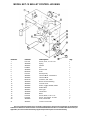
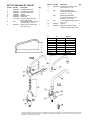
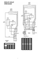
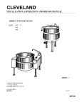
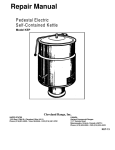
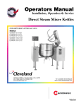
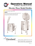
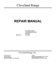
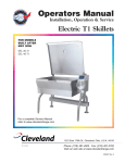
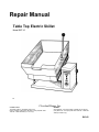
Repair Manual
Table Top Electric Skillet
Model SET-10
128S
Cleveland Range, Inc.
UNITED STATES
1333 East 179th St., Cleveland, Ohio 44110
Phone: (216)481-1900 •Telex: 98-0546 • FAX: (216)481-3782
Toll Free: 1-800-782-0040 (in U.S.A. only)
CANADA
8231 KeeleSt. • Concord, Ontario, Canada L4K 121 Phone:
(416) 660-4747 • FAX: (416) 660-4432 Toll Free: 1-800-3873562 (in Canada only)
SKI-01
MODEL SET-10 SKILLET
OPERATING CONTROLS
AND INDICATORS
For your better understanding and confidence, the following explanation of the control system
used on these skillets is offered.
Item No. Description
Function
5-6
Semi Tilt Arm and Knob (Control
Housing Dwg.)
While skillet is in a tilted position, push knob in and
rotate. This will keep the skillet in a semi-tilted
position when lowered.
13
ON/OFF Toggle Switch (Control
Housing Dwg.)
Controls electric power to the skillet.
15
Pilot Light
(Control Housing Dwg.)
The pilot light cycles on and off, indicating
power to the elements, controlled by the
thermostat.
20
5-6
Thermostat Control Knob (Control
Housing Dwg.)
Tilting Handle and Knob (Skillet
Bottom Dwg.)
This control knob allows the operator to select
various heat increments for operating the skillet.
This handle allows the operator to manually tilt
the skillet.
03
MODEL SET-10 SKILLET BOTTOM
Item No.
Part No.
1
2
3
4
5
6
SK50019
FA21024
SK00018
SK50028
KE50151
KE50803
Description
Washer, Spherical
Nut, 5/16-18
Element Block Assembly
Thermostat, High Limit (575°F) (302°C)
Knob, Handle
Handle
Qty.
16
16
3
1
1
1
Use only replacement parts which are factory supplied as to preserve the certification of Underwriters Laboratories.
American Gas Association. Canadian Standards Association or Canadian Gas Association (as applicable). The use of other than
factory supplied replacement pans will void the warranty
04
MODEL SET-10 SKILLET CONTROL HOUSING
Item No.
Part No.
Description
Qty.
1
2
3
4
5
6
7
8
9
10
11
12
13
14
15
16
17
18
19
20
21
FA11135
SK50038
SK50037
FA95013
SK00025
KE50442
FA11501
SK50054
SK50055
KE50749
SK50039
SK50050
SK50056
SK50062
SK50057
SK00028
SK00031
FA10135
FA10140
SK50060
SK50047
Screw, Cover, 10 - 24 x 1/2"
Spring
Washer
Pin
Semi Tilt Arm
Knob
Screw (Knob)
Terminal Block - End Section
Terminal Block
Contactor, 208 - 240V
Bronze Trunnion Bearing
Console Cover
Switch, Toggle, ON/OFF, DPST
Rubber Boot
Pilot Light
Thermostat
Bezel
Screw, Bezel, 6 - 32 x 1 1/4
Screw, Termostat 6 - 32 x 5/8
Knob, Thermostat
Trunnion Lock Collar
1
1
1
2
1
1
1
1
3
1
2
1
1
1
1
1
1
2
2
1
1
Use only replacement parts which are factory supplied as to preserve the certification of Underwriters
Laboratories. American Gas Association. Canadian Standards Association or Canadian Gas Association (as
applicable). The use of other than factory supplied replacement pans will void the warranty.
5
KETTLE AND SKILLET FAUCET
Item No.
1
2
3
4
5
6
7
Part No.
SE50020
SE50021
SE50022
FA00016
FA95022
SE50064
see chart
8
N/A
9
KE51401
Description
Hot Water Stem Assy.
Cold Water Stem Assy.
Yoke Connection Kit
"0" Ring
Retaining Ring
Spout Nut
3/4 spout (please see 3/4
spout chart below)
3/4 spout with Aerator (please
order Item No. 4. 5. 6. 7)
Single Pantry Control Valve
(incl. Item No. 2)
Qty.
1
1
1
1
1
1
1
1
1
Item No. Part No.
10
KE51403
Description
Double Pantry Control Valve
(incl. Item No. 1. 2. 3)
11
N/A
Old Style Single Pantry
Control Valve (please order
item NO 4. 5. 6. 7. 9)
N/A
Old Style Double Pantry
Control Valve (please order
Item No. 4. 5. 6. 7. 10)
1" Spout (please order item No 1
4.5.6. 7. 14)
"0" Ring
2
Adapter (to adapt new style
1
spout to old style control valve)
12
N/A
13
14
FA00115
SE50061
A
B
Part No.
4"
10"
6"
12 1/2"
10 3/4
5"
24"
20"
12 1/2"
8”
9"
22"
14""
14"
14""
9"
9"
9"
KE50833
KE50832
KE50831
KE50830
KE50829
KE50828
KE50827
KE50826
KE50825
Qty.
1
Use only replacement pans which are factory supplied as to preserve the certification of Underwriters Laboratories. American Gas
Association. Canadian tandards Association or Canadian Gas Association (as applicable). The us e of other than factory supplied
replacement parts will void the warranty.
TABLE TOP ELECTRIC SKILLET
SERVICING GUIDE
This section contains servicing information intended for use by Authorized Service Personnel.
A/ PROBLEM: Skillet fails to heat with pilot light on.
Probable Cause
Test and Remedy
1. Faulty contactor(s)
Check coil(s) and contacts of contactor(s).
Replace if necessary.
2. Faulty wiring
Check wiring to contactor(s). Replace if
necessary.
B/ PROBLEM: Skillet fails to heat with pilot light off. (power switch must .be on and thermostat set).
Probable Cause
Test and Remedy
1. Main power to skillet is off
Check incoming power at terminal block.
2. Defective power switch
With power source off, remove wiring from
switch and test for continuity. Or with wiring
connected and unit on, check for voltage
across terminals of switch. Voltage indicates
an open circuit. Replace switch if necessary.
3. Defective thermostat
Shut the unit off and disconnect wiring from
thermostat. Check for continuity of
thermostat. An open circuit while in the "ON"
position indicates a faulty thermostat. Or with
thermostat connected and unit on, check for
voltage across thermostat. Voltage indicates
an open circuit, indicating a faulty thermostat.
4. Defective high limit thermostat
Repeat above procedure used for defective
thermostat.
C/ PROBLEM: Skillet fails to reach maximum 425°F at #10 setting.
Probable Cause
Test and Remedy
1. Defective or improperly adjusted
As unit shuts off early, check for voltage
thermostat
across thermostat terminals. If there is
voltage across terminals, re-calibrate or
replace thermostat.
2. Defective safety thermostat
Repeat above procedure used for defective
thermostat.
D/ PROBLEM: Skillet has uneven heat over pan surface.
Probable Cause
Test and Remedy
1. Defective contactor
Check contactors for burned out contacts
and replace if required.
2. Defective heating element block
Check for continuity between element
terminals and from terminals to ground. Either
an open circuit between terminals or a short
to ground indicates a faulty element. Replace
if necessary.
3. Faulty wiring
Inspect condition of wires and connections to
elements and contactors. Repair if necessary.
4. Uneven torquing of aluminum heating
Follow element block torquing procedure.
blocks
7
VOLTS
208
VOLTS
KW
PH
AMPS
208/360
5.9
3
9.4 perPH
7.4
3
11.8 per PH
220/380
6.5
3
9.9 per PH
240/415
7.8
3
10.9 per PH
220.
230
240
8
KW
PH
AMPS
5.9
1
3
28.4
16.4 per PH
7.4
1
35.4
3
20.5 per PH
1
29.8
3
7.2 per PH
1
31.3
3
18.0 per PH
1
32.7
3
18.9 per PH
6.5
7.2
7.8