1
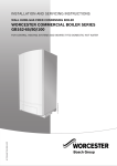
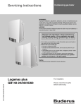
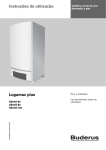
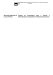
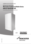
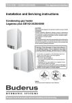
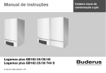
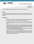
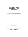
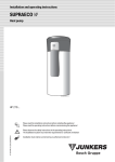
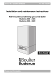
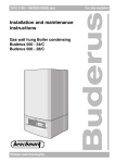
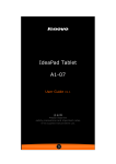
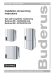
12
Maintenance
1
2
7 746 800 040-128.2TD
Fig. 85 Checking the ionization electrode
6720645916-85.1N
2
Fig. 84 Removing the burner plate and the burner seal
3
12.3.4 Checking ignition unit
DANGER:
B Close the gas valve prior to working on
components in contact with gas.
B Check for gas tightness after carrying out
work on components in contact with gas.
NOTICE
The glow ignitor is fragile.
B Handle with care.
NOTICE
If the seat of the cover plate leaks, the seal
can burn away.
B Check the cover plate for tightness.
• Check the individual components of the ignition unit
(fig. 86) for wear or contamination (fig. 85).
• If required, replace the ionization electrode and/or glow
ignitor.
4
5
1
5
6720615405-035.1TD
Fig. 86 Replacing the ignition unit
1
2
3
4
5
glow ignitor
Ionization electrode
Rubber seal
Cover plate with seal
Nut
12.3.5 Disconnect the condensate trap
• Disconnect the condensate trap hose (fig. 87, [3]) and
the rubber sleeve (fig. 87, [2]) from the condensate
trap (fig. 87, [1]).
• Turn the condensate trap a quarter rotation
counterclockwise (fig. 87).
After checking or replacing the ionization electrode
and/or the glow ignitor fit a new cover plate and rubber
seal.
Logamax plus GB162- L.B. 80/100 kW - Subject to modifications resulting from technical improvements!
55