1
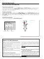
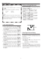
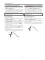
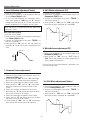
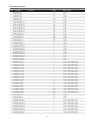
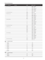
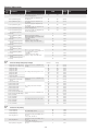
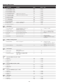
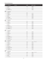
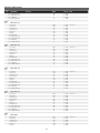
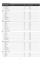
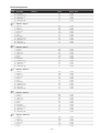
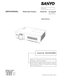
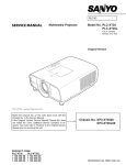
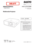
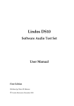
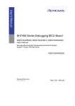
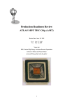
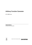
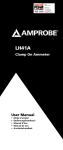
Notice
● CORRECTION
PRODUCTION CHANGE
SERVICE FLASH
ADD INFORMATION
FILE NO.
REVISION-3
Please add this notice to the Service Manual listed below.
Category : Multi-media Projector
Issued Date : Model : Effective from : PLC-WXU700A
Destination : Canada, U.S./Europe,
Asia, U.K. REF. NO. : December / 2010
Chassis No. KY7-WXU700A00
SM5111153
NOTE: Match the Chassis No. on the rating label of the projector with the Chassis No. in the
Service Manual.
If the Chassis. No. does not match the projector, additional Service Literature is
required. Only the difference service information is given in this manual. For detailed
service information, refer to the service manual original SM5111153-00 issued in
November 2009 for Model PLC-WXU700A.
Reason of Change:
- To correct the adjustment procedure on the Electrical Adjustments. (The Pedestal
Adjustment is not necessary for this model)
- To correct and update the information of Service Adjustment Data Table.
FILE WITH ORIGINAL SERVICE MANUAL (SM5111153)
Product Code
plc-WXU700A
1 122 457 20 (KY7AE)
1 122 458 20 (LY7AE)
1 122 458 22 (LY7CE)
REFERENCE NO. SM5111153-03
Electrical Adjustments
Service Adjustment Menu Operation
To enter the service mode
To enter the "Service Mode", press and hold the MENU button and SELECT button on the projector for more
than 3 seconds or press and hold the MENU button on the remote control for than 20 seconds. The service
menu appears on the screen as follows.
To adjust service data
Select the adjustment group no. by pressing the MENU button (increase) or SELECT button (decrease), and
select the adjustment item no. by pressing the pointer e or d button, and change the data value by pressing the
7 or 8 button. Refer to the “Service Adjustment Data Table” for further description of adjustment group no., item
no. and data value.
To exit the service mode
To exit the service mode, press the ON/STAND-BY button.
Service Mode
Input
Computer 1
Group No.
Data
0
Ver.
0
+179
R 0.00
KY7AE
Group No. Item No.
Data value
Memory IC (IC1391) Replacement
Memory IC on the main board stores the data for the
service adjustments, and should not be replaced except
for the case of defective device.
If replaced, the re-adjustments are required following to
the “Electrical Adjustments”.
The data of lamp replacement counter is stored in the
Memory IC.
Please note that the lamp replace counter will be reset
when the memory IC is replaced.
(Lamp replace counter cannot be set to the previous
value.)
● Caution to memory IC replacement
When memory IC is replaced with new one, the CPU
writes down the default data of the service adjustments
to the replaced IC as the mentioned on the service ad--
justment table. As these data are not the same data as
factory shipped data, it should be required to perform
the re-adjustments following to the “Electrical Adjustments”.
Please note that in this case the lamp replace counter
will be reset.
●C
aution of Main Board replacement (in the case
memory IC is not defective)
When the main board is replaced, memory IC should
be replaced with the one on previous main board. After
replacement, it should be required to perform the re-adjustments following to the “Electrical Adjustments”.
In this case, the lamp replace counter can be kept the
value as before.
Electrical Adjustments
Circuit Adjustments
CAUTION: The each circuit has been made by the fine adjustment at factory. Do not attempt to adjust the following
adjustments except requiring the readjustments in servicing otherwise it may cause loss of performance
and product safety. Before adjustment, please turn on the projector more than ten minutes.
WARNING : USE UV RADIATION EYE AND SKIN
PROTECTION DURING SERVICING.
CAUTION: To prevent suffer of UV radiation, those adjustments
must be completed within 25 minutes.
[Adjustment Condition]
● Input signal
Video signal .........................1.0Vp-p/75W terminated, 16 steps gray scale
(Composite video signal)
Component Video signal.......1.0Vp-p/75W terminated, 8 color 100% color
bar or 16 step gray scale (Component video
signal)
Computer signal....................0.7Vp-p/75W terminated, 16 steps gray scale
pattern
● Image control mode..........“STANDARD” mode unless otherwise noted.
16 steps gray scale pattern
White 100%
Black 100%
Note:
* Please refer to “Service Adjustment Menu Operation” for entering the
service mode and adjusting the service data.
W
White 100%
--
Y
C
G
M
R
B
BLK
Black 100%
Electrical Adjustments
After replacing the Power Board readjust the Output
voltage adjustment as follows.
2 .Reference Voltage Adjustment
1. Enter the service mode.
2. Receive the 16-step grey scale computer signal with
Computer 2 [RGB] mode.
3. Select group no. “106”, item no. “0” to ad-
just the voltage of TP_VMIDG to be 7.00 ±0.01V.
4. Select group no. “106”, item no. “1” to adjust
the voltage of TP35R to make the amplitude “D[Vpp]” to be 10.00 ±0.05V.
5. Select group no. “106”, item no. “2” to adjust
the voltage of TP35G to make the amplitude “D[Vpp]” to be 10.00 ±0.05V.
6. Select group no. “106”, item no. “3” to adjust
the voltage of TP35B to make the amplitude “D[Vpp]” to be 10.00 ±0.05V.
1. C
onnect a digital voltmeter to pins 1 (+) and 2 (-)
of K6A.
2. Adjust the voltage by using VR601 as following.
AC Input
230V Reading
370V ±2V
Caution:
Be sure to connect the lamp when taking this adjustment.
* This adjustment is not required even if the power
board is replaced because this adjustment is carried
out before parts shipment.
1. Fan Control adjustment
1. E
nter the service mode.
2. Connect a digital voltmeter to test point “TPFANA”
(+) and chassis ground (-). Select group no. “250”,
item no. “0” and change data value to adjust voltage
to be 4.5 ±0.1V.
3. Connect a digital voltmeter to test point “TPFANB”
(+) and chassis ground (-). Select group no. “250”,item
no. “2” and change data value to adjust voltage to be
4.5 ±0.1V.
4. Connect a digital voltmeter to test point “TPFANC”
(+) and chassis ground (-). Select group no. “250”,item
no. “4” and change data value to adjust voltage to be
4.5 ±0.1V.
5. Connect a digital voltmeter to test point “TPFANA”
(+) and chassis ground (-). Select group no. “250”,item
no. “1” and change data value to adjust voltage to be
13.5 ±0.1V.
6. Connect a digital voltmeter to test point “TPFANB”
(+) and chassis ground (-). Select group no. “250”,item
no. “3” and change data value to adjust voltage to be
13.5 ±0.1V.
7. C
onnect a digital voltmeter to test point “TPFANC”
(+) and chassis ground (-). Select group no. “250”,item
no. “5” and change data value to adjust voltage to be
13.5 ±0.1V.
--
㪛㩷㪲㪭㫇㫇㪴
3. Panel Type Check and Setting
* Before setting, you need to check which type of LCD panel is placed on the projector according to the item "LCD
Panel/Prism Ass'y removal" in the chapter "Optical Parts
Disassembly".
1. Enter the service mode.
2. Panel Type Check
Select group no. “290”, item no. “0”. Check the data
value as follows;
Data value: 0 For L-Type of LCD Panel
Data value: 20 For R-Type of LCD panel
3. Panel Type Setting
Select group no. “290”, item no. “1” and change data
value from 10 to 0 or 20 depending on your LCD Panel
type. When the data value reaches 0 or 20, it returns to
10 quickly. The gamma-characteristics changes according to your selection.
Electrical Adjustments
4. Auto Calibration adjustment [PC]
5. Auto Calibration adjustment [Component]
1. Enter the service mode.
2. Receive the 16-step grey scale computer signal with
Computer2 [RGB] mode.
3. To start the auto-calibration for PC adjustment, select
group no. “260”, item no. “0” and then change data
value from “0” to “1”. After the auto-calibration completed, "OK" will appear on the screen.
1. Enter the service mode.
2. Receive the 8 color 100% color bar 1080i-component
signal with Computer1 [Component] mode.
3. To start the auto-calibration for Component adjustment, select group no. “260”, item no. “0” and then
change data value from “0” to “1”. After the auto-calibration completed, "OK" will appear on the screen.
Below adjustments are performed when the above
auto calibration is failed.
Below adjustments are performed when the above
auto calibration is failed.
Gain adjustment [PC]
1. Enter the service mode.
2. Receive the 16-step grey scale computer signal with
Computer2 [RGB] mode.
3. Connect an oscilloscope to test point “TP35G” (+)
and chassis ground (-).
4. Select group no. “0”, item no. “3” and adjust the amplitude “a” to be minimum by changing the Data value.
5. Connect an oscilloscope to test point “TP35R” (+)
and chassis ground (-).
6. Select group no. “0”, item no. “4” and adjust the amplitude “a” to be minimum by changing the Data value.
7. Connect an oscilloscope to test point “TP35B” (+) and
chassis ground (-).
8. Select group no. “0”, item no. “5” and adjust the amplitude “a” to be minimum by changing the Data value.
Gain adjustment [Component]
1. Enter the service mode.
2. Receive the 16-step grey scale computer signal with
Computer1 [Component] mode.
3. Connect an oscilloscope to test point “TP35G” (+)
and chassis ground (-).
4. Select group no. “0”, item no. “3” and adjust the amplitude “a” to be minimum by changing the Data value.
White Level
(a)
White Level
(a)
--
Electrical Adjustments
6. Auto Calibration adjustment [Video]
8. 50% White adjustment [PC]
1. Enter the service mode.
2. Receive the 16-step grey scale composite video signal with Video [Video] mode.
3. To start the auto-calibration for Component adjustment, select group no. “260”, item no. “0” and then
change data value from “0” to “1”. After the auto-calibration completed, "OK" will appear on the screen.
1. Enter the service mode.
2. Receive the 16-step grey scale computer signal with
Computer2 [RGB] mode.
3. Connect an oscilloscope to test point “TP35G” (+)
and chassis ground (-).
4. Select group no. “104”, item no. “220” and change
data value to adjust amplitude “a” to be 1.2V.
below adjustment is performed when the above auto
calibration is failed.
Gain adjustment [Video]
1. Enter the service mode.
2. Receive the 16-step grey scale composite video signal
with Video [Video] mode.
3. Connect an oscilloscope to test point “TP35G” (+)
and chassis ground (-).
4. Select group no. “20”, item no. “0” and adjust the
amplitude “a” to be minimum by changing the Data
value.
white level
(a)
white level
9. White Balance adjustment [PC]
White Level
1. Enter the service mode.
2. Receive the 16-step gray scale computer signal with
Computer2 [RGB] mode.
3. Select group no. “104” item no. “217” (Red) or
“223” (Blue), and change Data values respectively to
make a proper white balance.
(a)
Confirm that the same white balance is obtained in video and computer input.
7. Common Center adjustment
1. Enter the service mode.
2. Receive the 50%-Whole Gray computer signal with
Computer2 [RGB] mode.
3. Select group no.“ 104”, item no.“ 76” and change
data value to“ 2” to reduce the panel frequency.
4. Project only green light component to the screen.
5. Select group no.“ 105”, item no.“ 10” and change
data value to obtain the minimum flicker on the
screen.
6. Project only red light component to the screen.
7. Select item no.“ 9” and change data value to obtain
the minimum flicker on the screen.
8. Project only blue light component to the screen.
9. Select item no.“ 11" and change data value to obtain
the minimum flicker on the screen.
10. Select group no.“ 104”, item no.“ 76” and change
data value to“ 0” to reset the panel frequency.
10. 50% White adjustment [Video]
1. Enter the service mode.
2. Receive the 16-step grey scale composite video signal with Video[Video] mode.
3. Connect an oscilloscope to test point “TP35G” (+)
and chassis ground (-).
5. Select group no. “104”, item no. “220” and change
data value to adjust amplitude “a” to be 1.2V.
white level
--
(a)
white level
Electrical Adjustments
11.White Balance adjustment [Video]
13. Color Shading Correction adjustment
1. Enter the service mode.
2. Receive the 16-step grey scale composite video signal with Video[Video] mode.
3. Select group no. “104” item no. “217” (Red) or
“223” (Blue), and change Data values respectively to
make a proper white balance.
If the correction of the Color shading adjustment is necessary, please adjust the "Color shading" by using the
"COLOR SHADING CORRECTION" software supplied
separately.The color shading correction adjustment for
this model should be performed with the whole-gray
patterns specified as below.
4-input patterns:
6% gray, 12.5% gray, 25% gray, 50% gray
Confirm that the same white balance is obtained in video and computer input.
Note On White Uniformity Adjustment
If you find the color shading on the screen, please
adjust the white uniformity by using the proper computer
and “Color Shading Correction” software supplied separately.
12.Keystone Offset adjustment
After replacing the G-sensor circuit (IC3851, IC1802
and peripheral circuit), readjust the Keystone Offset
adjustment as follows.
1. P
ut the projector on a horizontal place with the
adjustable feet being minimum range and then enter
the service mode.
2. Select group no.“ 75”, item no.“ 3” and set data
value from“ 0” to“ 5”.
3. By pressing the SELECT button, the Keystone
Offset adjustment will start.
4. When it has completed, the "OK" message will
appear on the screen.
5. By pressing any button on the projector or the
remote control, the "OK" message will disappear.
(Data value of Group no.“ 102”, item no.“ 3” will be
back from“ 5” to“ 0” for initial value.)
The software can be order as ordered as follows;
COLOR SHADING CORRECTION Ver. 4.00
Service Parts No.
645 075 9611
--
Electrical Adjustments
Test Points and Locations
MAIN BOARD
K8S
K6001
K6K
K8P
K6J
IC6002
K8G
TPFANB
TPFANC
IC501
TP35B
K40B
TP_VMIDR
TP35B
K5B
TP_VMIDR
IC801
K10A
TP35G
IC531
K5G
K10B
K8E
IC561
TP35R
K10C
TPFANA
K5R
TP35R
--
K8N
K6M
K6L
Electrical Adjustments
Service Adjustment Data Table
Group/
Item
Group 0
Item Name
These initial values are the reference data written from the
CPU ROM to memory IC when replaced new memory IC. The
adjustment items indicated with“ ✻” are required to readjust
following to the“ Electrical adjustments”. Other items should
be used with the initial data value.
Function
Initial
Range
Note
265/200/200/200/200/265
0 - 1023
* G-Gain Adjustmen
265/205/205/205/205/265
0 - 1023
* R-Gain Adjustmen
255/205/205/205/205/265
0 - 1023
* B-Gain Adjustmen
2/4/4
1/1/0
0 - 15
0-1
*/4/4
0 - 15
*/4/4
0 - 15
235/120/120/135/135
0 - 1023
235/140/140/155/155
0 - 1023
235/140/140/155/155
0-1023
175/185
0 - 1023
Composite / S-Video
* Gain Adjustment [Video]
405/440
0 - 1023
Composite / S-Video
AD Converter (PW392)
3 ADC G-GAIN
4 ADC R-GAIN
5 ADC B-GAIN
10 SOGTH
11 SOGHYSDIS
12 HS1TH
13 HS0TH
YCbCr 480i (575i) / YCbCr 480p (575p)
/ YCbCr 720p (720p50) / YCbCr 1080i
(1035i, 1080i50) /
SCART
YCbCr 480i (575i) / YCbCr 480p (575p)
/ YCbCr 720p (720p50) / YCbCr 1080i
(1035i, 1080i50) /
SCART
YCbCr 480i (575i) / YCbCr 480p (575p)
/ YCbCr 720p (720p50) / YCbCr 1080i
(1035i, 1080i50) /
SCART
RGB / COMPONENT / SCART
RGB / COMPONENT / SCART
H Sync1 Threshold
RGB / COMPONENT / SCART
H Sync0 Threshold
RGB / COMPONENT / SCART
Group 10 Sync Processor
3 ADC G-GAIN
4 ADC R-GAIN
5 ADC B-GAIN
Group
20
Video Decoder *R : Read Only Value
0 Y Level
1 C Level
10 XCXL Parameter
2
0-4
NTSC/PAL
0 - 9999
NTSC/PAL
0x1000
0 - 9999
NTSC/PAL
0
4
3
3
0-1
0-7
0-3
0-3
for PAL/SECAM only
3
0-3
DVI Equalizer CHO Boost Value
DVI Equalizer CH1 Boost Value
DVI Equalizer CH2 Boost Value
-
0-7
0-7
0-7
0 IP Mode
Sets for IP Off
1
0-1
1 3:2 PullDown Mod e
bit0 : Global Motion
bit1 : Video Motion
0 : 2:3pull down & 2:2pull down
1 : 2:3pull down
2 : 2:2pull down
0: Detect Y or UV, Noise Reduction
1: Detect Y, YUV for Noise Reduction
Analog YUV : PC/Video/S-Video/
Component
Digital YUV : HDMI
<NSYUVEN>
1
1-3
0
0-2
1
0-1
0
0-1
12 Sync Amp High
13
14
15
16
20
Luma Setup Enable
Anti-Alias Filter
Anti-Alias Downsample
Anti-Alias High Frequency
Comb 3D Cross-Luma Top/
Bottom Amplitude
Effective only NTSC Signal
DVI Equalizer(DS16E5110)
0 CH0 Boost Data
1 CH1 Boost Data
2 CH2 Boost Data
Group
40
Composite / S-Video - Y Level (ADC
RGB Gain)
Composite / S-Video - C Level (ADC
Saturation)
XCXL Level
Minimum sync amplitude threshold
for HLOCK 1 to 0 transition
Minimum sync amplitude threshold
for HLOCK 0 to 1 transition
7.5IRE Mode
Anti-Alias Filter
Anti-Alias Downsample
Anti-Alias High Frequency
0x0700
11 Sync Amp Low
Group
35
PC/YCbCr 480i (575i) / YCbCr 480p
(575p) / YCbCr 720p (720p50) / YCbCr
1080i (1035i, 1080i50)
PC/YCbCr 480i (575i) / YCbCr 480p
(575p) / YCbCr 720p (720p50) / YCbCr
1080i (1035i, 1080i50)
PC/YCbCr 480i (575i) / YCbCr 480p
(575p) / YCbCr 720p (720p50) / YCbCr
1080i (1035i, 1080i50)
General
2 Detect Film Mode Enable
3 NR Enable for Digital YUV
4 NR Enable for Digital YUV
--
0: IP Block not used
1: IP OFF used with IP Block
bit0 : Global Motion
bit1 : Video Motion
0 : 2:3pull down & 2:2pull down
1 : 2:3pull down
2 : 2:2pull down
Electrical Adjustments
Group/
Item
Item Name
Group
41
Deinterlacer setting Effective only for Progressive Mode 1, Film mode.
Function
Range
0 - 255
Adaptive Weight
0 Motion
Value
<KDEINT>
30
1 Angle Interpolation Level
0 : Conservative <====> 4 :
Aggressive
<CUELPFEN>
4
0-5
0
0 -255
2 CUE Low Pass Filter Enable
Group
42
Note
Deinterlacer setting Effective only for Progressive Mode2 mode.
Adaptive Weight
0 Motion
Value
<KDEINT>
0
0 - 255
1 Angle Interpolation Level
0 : Conservative <====> 4 :
Aggressive
<CUELPFEN>
2
0-5
0
0 - 255
2 CUE Low Pass Filter Enable
Group
47
Noise Reduction (Time) Effective only for N.R L1
0 Noise Pixel Range
1 Noise Region 0
2 Noise Region 1
3 Noise Region 2
4 Noise Gain Level
Group
49
<NSRANGEY> / <NSRANGEUV>
<NSREGIONY0> /
<NSREGIONUV0>
<NSREGIONY1> /
<NSREGIONUV1>
<NSREGIONY2> /
<NSREGIONUV2>
<NSFILTERY**> /
<NSFILTERUV**>
1
0-2
12
0 - 1023
24
0 - 1023
40
0 - 1023
100
0 - 255
Noise Reduction (Time) Effective only for N.R L2
0 Noise Pixel Range
1 Noise Region 0
2 Noise Region 1
3 Noise Region 2
4 Noise Gain Level
Group
50
<NSRANGEY> / <NSRANGEUV>
<NSREGIONY0> /
<NSREGIONUV0>
<NSREGIONY1> /
<NSREGIONUV1>
<NSREGIONY2> /
<NSREGIONUV2>
<NSFILTERY**> /
<NSFILTERUV**>
1
0-2
12
0 - 1023
24
0 - 1023
40
0 - 1023
100
0 - 255
2:2pull down setting
Film Detection Sensitivity
<FILMSTVT22>
22Film Mode Threshold Low <FILMTHRD22A>
22Film Mode Threshold High <FILMTHRD22B>
Video Motion Window Start <VOFSTARX>
X
Video Motion Window Start <VOFSTARX>
X
Video Motion Window Start <VOFSTARY>
Y
Video Motion Window Start <VOFSTARY>
Y
0 22Film Mode Sensitivity
4
1-5
80
120
0 - 1023
0 - 1023
10
0 - 255
10
0 - 255
10
0 - 255
10
0 - 255
0 Global Motion Sensitivity
4
1-5
1
4
1-5
1
2
3
4
5
6
Group
51
2:3pull down setting
2
3
4
5
6
7
8
9
Group
55
Initial
Film Detection Sensitivity
<FILMSTVT23>
Film Detection Sensitivity
Video Motion Sensitivity
<VOFSTVT>
Video Motion Threshold Low <VOFTHRDA>
Video Motion Threshold
<VOFTHRDB>
High
Global Motion Threshold
<GMDTHRD>
23Film Mode Threshold
<FILMTHRD23>
Global Motion Window Start X <GMDSTARX>
Global Motion Window Stop X <GMDSTOPX>
Global Motion Window Start Y <GMDSTARY>
Global Motion Window Stop Y <GMDSTOPY>
120
0 - 1023
180
0 - 1023
100
10
10
10
10
10
0 - 1023
0 - 1023
0 - 255
0 - 255
0 - 255
0 - 255
1
3
0-1
0 - 15
LTI /CTI
0 Video Enhancement Enable
1 DLTI Gain
VEHEN
DLTIGAIN
-10-
Range of detective for Film mode
Range of detective for Film mode
Range of detective for Film mode
Range of detective for Film mode
Electrical Adjustments
Group/
Item
2
3
4
5
6
7
Group
60
Item Name
Function
DLTI Frequency
Bypass Anti-Alias Filter
Lower DCTI Frequency
DCTI Gain
DCTI Frequency
Color Shift Limit
DLTIFREQ
DTIBYPASSAAL
LOWERDCTIFREQ
DCTIGAIN
DCTIFREQ
COLORSHIFTLMT
Initial
Range
2
0
1
4
0
3
0-3
0-1
0-1
0 - 15
0-3
0-3
Note
534/534/578/492/492/512
512/512/512/512/512/512
560/560/512/512/560/512
90/90/90/90/90/90
0 - 1023
0 - 1023
0 - 1023
0-180
8/8/8/8/8/8
0 - 37
8/8/8/8/8/8
0 - 37
8/8/10/16/10/16/
0 - 37
512/512/512/512/512/512
512/512/512/512/512/512
512/5/12/512/512/512/512
512/512/512/512/512/512
512/512/512/512/512/512
512/512/512/512/512/512
60/60/60/60/60/60
90/90/90/90/90/90
140/140/140/140/140/140
10/10/10/10/10/10
10/10/10/10/10/10
40/40/40/40/40/40
40/40/40/40/40/40
40/40/40/40/40/40
20/20/20/20/20/20
20/20/20/20/20/20
20/20/20/20/20/20
0 - 1023
0 - 1023
0 - 1023
0 - 1023
0 - 1023
0 - 1023
0-1000
0-1000
0-1000
0-1000
0-1000
0- 1000
0- 1000
0-1000
0-1000
0-1000
0-1000
0
0
0
0
5
64
1
5
160
32
61
-1056 1056
0-1
0-1
0-1
1 - 255
1 - 255
1 - 10
1 - 10
0 - 1024
0 - 1024
0 - 1024
100
266
0-4095
0 - 1023
266
266
26
273
1
1
1
48
51
27
1093
2
0
3
1
0
0 - 1023
0-1023
0-256
0-4095
0-12
1 - 12
0 - 12
0 - 127
0 - 255
0 - 255
0 - 2047
0-3
0-9
0 - 1023
0-1
1: Enable, 0: Disable
0-1
1: Enable, 0: Disable
Image
0
1
2
3
4
5
6
7
8
9
10
11
12
13
14
15
16
17
18
19
20
21
22
23
Center Contrast
Center Brightness
Center Color
Center Tint
Fixed Sharpness (Up
Scaling)
Fixed Sharpness (Down
Scaling)
Center Sharpness(Models
without FPGA)
Center WB Red
Center WB Green
Center WB Blue
Center BB Red
Center BB Green
Center BB Blue
Alpha Contrast
Alpha Brightness
Alpha Color
Alpha Tint
Alpha Sharpness
Alpha WB Red
Alpha WB Green
Alpha WB Blue
Alpha BB Red
Alpha BB Green
Alpha BB Blue
Composite / S-Video / Component
/ Digital /D-RGB-Video /AnalogRGB
/ RGB-Video / HDCP-PC /HDCP-AV
/SCART / PJ-Net
Setting Value=
(MENU Value - MENU Center Value )
x Alpha / 10 + Center
For moels without FPGA:
Sharpness setting Value=
Center-(Menu Value-MENU Center
Value)xAlpha/10
[Setting Value to PW]
Contrast [Max] 1023 [Min] 0
Brightness [Max] 1023 [Min] 0
Color
[Max] 1023 [Min] 0
Tint
[Max] 180 [Min] 0
Sharpness [Max] 57 [Min] 0
Group75 : Auto Keystone Setup Value
0 OFFSET
1
2
3
4
5
6
7
8
9
10
OFFSET SWITCH
DEBUG MODE
SERVICE CALIBRATION
LOCK COUNT
DELT VERT RESULT
ANGLE 1 COUNT
ANGLE 2 COUNT
BLIND SECTOR 1
BLIND SECTOR 3
BLIND SECTOR BIAS
Group104 : Panel (EP7111) Services
0 FRP_SET
1 DXOut_R
2
3
4
5
6
7
8
9
10
11
12
13
14
15
16
17
DXOut_G
DXOut_B
H_Change_Pos
SH_Pos
SH_Pos_R
SH_Pos_G
SH_Pos_B
NGR_Pos
NGR_Width
FRP_Pos
SWAP_InOut
OSD_Pos
OSD_Ptn
GammaCtrl
GammaCtrl_Ena
GammaCtrl_PreEnable
-11-
Electrical Adjustments
Group/
Item
18
19
20
21
22
23
24
25
26
27
28
29
30
31
32
33
34
35
36
37
38
39
40
41
42
43
44
45
46
47
48
49
50
51
52
53
54
55
56
57
58
59
60
61
62
63
64
65
66
67
68
69
70
71
72
73
74
75
76
77
78
79
80
81
82
83
84
85
Initial
Range
REF_GatePos
REF_GateDur
BasePos_R
BasePos_G
BasePos_B
RGB_sIDEmODE
LineCont
GhostPos_R
GhostPos_G
GhostPos_B
GHOSTCoef_R_C
GHOSTCoef_R_S
GHOSTCoef_R_E
GHSTCoef_G_C
GHSTCoef_G_S
GHSTCoef_G_E
GHSTCoef_B_C
GHSTCoef_B_S
GHSTCoef_B_E
GHSTCoef_1R
GHSTCoef_1G
GHSTCoef_1B
GHSTCoef_2R
GHSTCoef_2G
GHSTCoef_2B
BlkGHSTCoef_R
BlkGHSTCoef_G
BlkGHSTCoef_B
CRSTLKCoef_R_C
CRSTLKCoef_R_S
CRSTLKCoef_R_E
CRSTLKCoef_G_C
CRSTLKCoef_G_S
CRSTLKCoef_G_E
CRSTLKCoef_B_C
CRSTLKCoef_B_S
CRSTLKCoef_B_E
ColshdCtrl
ColshdCtrl_Ena
ColshdCtrl_PreEna
Colshd_RLMin
Colshd_RLMid2
Colshd_RLMid1
Colshd_RLMax
Colshd_GLMin
Colshd_GLMid2
Colshd_GLMid1
Colshd_GLMax
Colshd_BLMin
Colshd_BLMid2
Colshd_BLMid1
Colshd_BLMax
Colshd_Pre_Tbl
EnaHSync
Item Name
Function
46
155
6
6
6
0
0
6
6
6
0
128
128
0
128
128
0
128
128
0
0
0
0
0
0
0
0
0
0
128
133
0
128
133
0
128
133
16
1
0
257
419
559
671
257
419
559
671
257
419
559
671
0
1
0 - 1023
0 - 1023
0 -11
0 - 11
0 - 11
0 -7
0 -4095
0 - 23
0 - 23
0 - 23
0-2047
0-255
0-255
0-2047
0-255
0-255
0-2047
0-255
0-255
0-2047
0-2047
0-2047
0-2047
0-2047
0-2047
0-2047
0-2047
0-2047
0-2047
0-255
0-255
0-2047
0-255
0-255
0-2047
0-255
0-255
0-511
0-1
0-1
0-1023
0-1023
0-1023
0-1023
0-1023
0-1023
0-1023
0-1023
0-1023
0-1023
0-1023
0-1023
0-255
0-1
OutPPos_H
Pixel_CONT_Out
H_Sync
V_Sync
FlickerMode
EnaVSync
EnbyPosUp1
EnbyPosDwn1
EnbyPosUp2
EnbyPosDwn2
FrmIRRMode
CRCTCoef_R_C
CRCTCoef_R_S
CRCTCoef_R_E
120
2048
0
3
0
0
32
827
32
827
0
0
128
128
0-2047
0-4095
0-2047
0-255
0-3
0-1
0-255
0-1023
0-255
0-1023
0-3
0-2047
0-255
0-255
-12-
Note
MIN<-->MAX cyclation
MIN<-->MAX cyclation
MIN<-->MAX cyclation
MIN<-->MAX cyclation
MIN<-->MAX cyclation
MIN<-->MAX cyclation
MIN<-->MAX cyclation
MIN<-->MAX cyclation
MIN<-->MAX cyclation
MIN<-->MAX cyclation
MIN<-->MAX cyclation
MIN<-->MAX cyclation
MIN<-->MAX cyclation
MIN<-->MAX cyclation
MIN<-->MAX cyclation
1: Enable, 0: Disable
1: Enable, 0: Disable
Electrical Adjustments
Group/
Item
86
87
88
89
90
91
92
93
94
95
96
97
98
99
100
101
102
103
104
105
106
107
108
109
110
111
112
113
114
115
116
117
118
119
120
121
122
123
124
125
126
127
128
129
130
131
132
133
134
135
136
137
138
139
140
141
Initial
Range
CRCTCoef_G_C
CRCTCoef_G_S
CRCTCoef_G_E
CRCTCoef_B_C
CRCTCoef_B_S
CRCTCoef_B_E
CRSTLK_COEF2_R_C
CRSTLK_COEF2_R_S
CRSTLK_COEF2_R_E
CRSTLK_COEF2_G_C
CRSTLK_COEF2_G_S
CRSTLK_COEF2_G_E
CRSTLK_COEF2_B_C
CRSTLK_COEF2_B_S
CRSTLK_COEF2_B_E
OutputLimitMax_R
OutputLimitMax_G
OutputLimitMax_B
VideoRRefCont_H
VideoRRefCont_L
DCOffset_MNS_R
DCOffset_MNS_R_01
DCOffset_MNS_R_02
DCOffset_MNS_R_03
DCOffset_MNS_R_04
DCOffset_MNS_R_05
DCOffset_MNS_R_06
DCOffset_MNS_R_07
DCOffset_MNS_R_08
DCOffset_MNS_R_09
DCOffset_MNS_R_10
DCOffset_MNS_R_11
DCOffset_MNS_R_12
DCOffset_PLS_R
DCOffset_PLS_R_01
DCOffset_PLS_R_02
DCOffset_PLS_R_03
DCOffset_PLS_R_04
DCOffset_PLS_R_05
DCOffset_PLS_R_06
DCOffset_PLS_R_07
DCOffset_PLS_R_08
DCOffset_PLS_R_09
DCOffset_PLS_R_10
DCOffset_PLS_R_11
DCOffset_PLS_R_12
Lvl9Mode_R_0000
Lvl9Mode_R_0512
Lvl9Mode_R_1024
Lvl9Mode_R_1536
Lvl9Mode_R_2048
Lvl9Mode_R_2560
Lvl9Mode_R_3072
Lvl9Mode_R_3584
Lvl9Mode_R_4096
VideoGRefCont_H
0
128
128
0
128
128
2045
128
128
2045
128
128
2045
128
128
4095
4095
4095
4088
450
0
0
0
0
0
0
0
0
0
0
0
0
0
0
0
0
0
0
0
0
0
0
0
0
0
0
18
15
12
8
2
1023
1020
1018
1018
4088
0-2047
0-255
0-255
0-2047
0-255
0-255
0-2047
0-255
0-255
0-2047
0-255
0-255
0-2047
0-255
0-255
0-4095
0-4095
0-4095
0-4095
0-4095
0-1023
0-2047
2047
0-2047
0-2047
0-2047
0-2047
0-2047
0-2047
0-2047
0-2047
0-2047
0-2047
0-1023
0-2047
0-2047
0-2047
0-2047
0-2047
0-2047
0-2047
0-2047
0-2047
0-2047
0-2047
0-2047
0-1023
0-1023
0-1023
0-1023
0-1023
0-1023
0-1023
0-1023
0-1023
0-4095
142
143
144
145
146
147
148
149
150
151
152
153
VideoGRefCont_L
DCOffset_MNS_G
DCOffset_MNS_G_01
DCOffset_MNS_G_02
DCOffset_MNS_G_03
DCOffset_MNS_G_04
DCOffset_MNS_G_05
DCOffset_MNS_G_06
DCOffset_MNS_G_07
DCOffset_MNS_G_08
DCOffset_MNS_G_09
DCOffset_MNS_G_10
450
0
0
0
0
0
0
0
0
0
0
0
0-4095
0-1023
0-2047
0-2047
0-2047
0-2047
0-2047
0-2047
0-2047
0-2047
0-2047
0-2047
Item Name
Function
-13-
Note
MIN<-->MAX cyclation
MIN<-->MAX cyclation
MIN<-->MAX cyclation
MIN<-->MAX cyclation
MIN<-->MAX cyclation
MIN<-->MAX cyclation
MIN<-->MAX cyclation
MIN<-->MAX cyclation
MIN<-->MAX cyclation
MIN<-->MAX cyclation
MIN<-->MAX cyclation
MIN<-->MAX cyclation
MIN<-->MAX cyclation
MIN<-->MAX cyclation
MIN<-->MAX cyclation
MIN<-->MAX cyclation
MIN<-->MAX cyclation
MIN<-->MAX cyclation
MIN<-->MAX cyclation
MIN<-->MAX cyclation
MIN<-->MAX cyclation
MIN<-->MAX cyclation
MIN<-->MAX cyclation
MIN<-->MAX cyclation
MIN<-->MAX cyclation
MIN<-->MAX cyclation
MIN<-->MAX cyclation
MIN<-->MAX cyclation
MIN<-->MAX cyclation
MIN<-->MAX cyclation
MIN<-->MAX cyclation
MIN<-->MAX cyclation
Electrical Adjustments
Group/
Item
154
155
156
157
158
159
160
161
162
163
164
165
166
167
168
169
170
171
172
173
174
175
176
177
178
179
180
181
182
183
184
185
186
187
188
189
190
191
192
193
194
195
196
197
198
199
200
201
202
203
204
205
206
207
208
209
210
211
212
213
214
215
Initial
Range
Note
DCOffset_MNS_G_11
DCOffset_MNS_G_12
DCOffset_PLS_G
DCOffset_PLS_G_01
DCOffset_PLS_G_02
DCOffset_PLS_G_03
DCOffset_PLS_G_04
DCOffset_PLS_G_05
DCOffset_PLS_G_06
DCOffset_PLS_G_07
DCOffset_PLS_G_08
DCOffset_PLS_G_09
DCOffset_PLS_G_10
DCOffset_PLS_G_11
DCOffset_PLS_G_12
Lvl9Mode_G_0000
Lvl9Mode_G_0512
Lvl9Mode_G_1024
Lvl9Mode_G_1536
Lvl9Mode_G_2048
Lvl9Mode_G_2560
Lvl9Mode_G_3072
Lvl9Mode_G_3584
Lvl9Mode_G_4096
VideoBRefCont_H
VideoBRefCont_L
DCOffset_MNS_B
DCOffset_MNS_B_01
DCOffset_MNS_B_02
DCOffset_MNS_B_03
DCOffset_MNS_B_04
DCOffset_MNS_B_05
DCOffset_MNS_B_06
DCOffset_MNS_B_07
DCOffset_MNS_B_08
DCOffset_MNS_B_09
DCOffset_MNS_B_10
DCOffset_MNS_B_11
DCOffset_MNS_B_12
DCOffset_PLS_B
DCOffset_PLS_B_01
DCOffset_PLS_B_02
DCOffset_PLS_B_03
DCOffset_PLS_B_04
DCOffset_PLS_B_05
DCOffset_PLS_B_06
DCOffset_PLS_B_07
DCOffset_PLS_B_08
DCOffset_PLS_B_09
DCOffset_PLS_B_10
DCOffset_PLS_B_11
DCOffset_PLS_B_12
Lvl9Mode_B_0000
Lvl9Mode_B_0512
Lvl9Mode_B_1024
Lvl9Mode_B_1536
Lvl9Mode_B_2048
Lvl9Mode_B_2560
Item Name
Function
0
0
0
0
0
0
0
0
0
0
0
0
0
0
0
18
15
12
8
2
1023
1020
1018
1018
450
4088
0
0
0
0
0
0
0
0
0
0
0
0
0
0
0
0
0
0
0
0
0
0
0
0
0
0
18
15
12
8
2
1023
0-2047
0-2047
0-1023
0-2047
0-2047
0-2047
0-2047
0-2047
0-2047
0-2047
0-2047
0-2047
0-2047
0-2047
0-2047
0-1023
0-1023
0-1023
0-1023
0-1023
0-1023
0-1023
0-1023
0-1023
0-4095
0-4095
0-1023
0-2047
0-2047
0-2047
0-2047
0-2047
0-2047
0-2047
0-2047
0-2047
0-2047
0-2047
0-2047
0-1023
0-2047
0-2047
0-2047
0-2047
0-2047
0-2047
0-2047
0-2047
0-2047
0-2047
0-2047
0-2047
0-2047
0-1023
0-1023
0-1023
0-1023
0-1023
MIN<-->MAX cyclation
MIN<-->MAX cyclation
MIN<-->MAX cyclation
MIN<-->MAX cyclation
MIN<-->MAX cyclation
MIN<-->MAX cyclation
MIN<-->MAX cyclation
MIN<-->MAX cyclation
MIN<-->MAX cyclation
MIN<-->MAX cyclation
MIN<-->MAX cyclation
MIN<-->MAX cyclation
MIN<-->MAX cyclation
MIN<-->MAX cyclation
MIN<-->MAX cyclation
MIN<-->MAX cyclation
MIN<-->MAX cyclation
MIN<-->MAX cyclation
MIN<-->MAX cyclation
MIN<-->MAX cyclation
MIN<-->MAX cyclation
MIN<-->MAX cyclation
MIN<-->MAX cyclation
MIN<-->MAX cyclation
Lvl9Mode_B_3072
Lvl9Mode_B_3584
Lvl9Mode_B_4096
VideoCont_R
1020
1018
1018
2048
2048
2000
2048
2048
2048
2048
0-1023
0-1023
0-1023
0-4095
0-4095
0-4095
0-4095
0-4095
0-4095
0-4095
MIN<-->MAX cyclation
MIN<-->MAX cyclation
MIN<-->MAX cyclation
Standard
Dynamic
Real
BlackBoard
R_Board
B_Board
Y_Board
-14-
MIN<-->MAX cyclation
MIN<-->MAX cyclation
MIN<-->MAX cyclation
MIN<-->MAX cyclation
MIN<-->MAX cyclation
MIN<-->MAX cyclation
MIN<-->MAX cyclation
MIN<-->MAX cyclation
MIN<-->MAX cyclation
MIN<-->MAX cyclation
MIN<-->MAX cyclation
MIN<-->MAX cyclation
MIN<-->MAX cyclation
MIN<-->MAX cyclation
MIN<-->MAX cyclation
MIN<-->MAX cyclation
MIN<-->MAX cyclation
MIN<-->MAX cyclation
MIN<-->MAX cyclation
MIN<-->MAX cyclation
MIN<-->MAX cyclation
MIN<-->MAX cyclation
MIN<-->MAX cyclation
MIN<-->MAX cyclation
MIN<-->MAX cyclation
MIN<-->MAX cyclation
MIN<-->MAX cyclation
MIN<-->MAX cyclation
MIN<-->MAX cyclation
MIN<-->MAX cyclation
MIN<-->MAX cyclation
MIN<-->MAX cyclation
Electrical Adjustments
Group/
Item Name
Item
216 VideoBright_R
Function
Initial
Range
Note
0
0
0
24
0
30
0
24
2048
2048
2048
2048
2000
2000
2010
2000
1900
1940
0
0
0
0
24
24
0
0
2048
2048
2048
2048
2000
2048
2048
1860
2048
2020
0
0
0
0
40
0
36
24
2048
2048
0-4095
0-4095
0-4095
0-4095
0-4095
0-4095
0-4095
0-4095
0-2048
0-2048
0-4095
0-4095
0-4095
0-4095
0-4095
0-4095
0-4095
0-4095
0-4095
0-4095
0-4095
0-4095
0-4095
0-4095
0-4095
0-4095
0-2048
0-2048
0-4095
0-4095
0-4095
0-4095
0-4095
0-4095
0-4095
0-4095
0-4095
0-4095
0-4095
0-4095
0-4095
0-4095
0-4095
0-4095
0-2048
0-2048
Standard
Dynamic
Real
BlackBoard
R_Board
B_Board
Y_Board
G_Board
PC
AV
Standard
Dynamic
Real
BlackBoard
R_Board
B_Board
Y_Board
G_Board
Standard
Dynamic
Real
BlackBoard
R_Board
B_Board
Y_Board
G_Board
PC
AV
Standard
Dynamic
Real
BlackBoard
R_Board
B_Board
Y_Board
G_Board
Standard
Dynamic
Real
BlackBoard
R_Board
B_Board
Y_Board
G_Board
PC
AV
201_R
601_G
A01_B
202_R
602_G
A02_B
205_R
605_G
A05_B
300_R
4
4
4
40
40
40
26
26
26
130
0-31
0-31
0-31
28-64
28-64
28-64
0-31
0-31
0-31
0-255
10 700_G
11 B00_B
130
130
0-255
0-255
178
242
242
242
0-255
0-255
0-255
0-255
217 VideoGammaShift_R
218 VideoCont_G
219 VideoBright_G
220 VideoGammaShift_G
221 VideoCont_B
222 VideoBright_B
223 VideoGammaShift_B
Group
105
Panel Services(6170)
0
1
2
3
4
5
6
7
8
9
Group
106
Panel Service(62334)
0
1
2
3
VMID
VREF_R
VREF_G
VREF_B
-15-
Electrical Adjustments
Group/
Item
Group
200
Item Name
Function
Initial
Range
Note
Option
Prohibition (Forced No
0 Logo
Brand)
Logo Prohibition (0: Menu, 1: Forced,
2: China, 3-9: not used)
0
0-2
Effective after AC On
1 RS232C Baudrate
Baud Rate
0
0-2
0: 19200bps, 1: 9600bps, 2:
115200bps
4 CABLE SW
Debug Command
5 PW
Enable
Long Cable
0
0 - 10
0
0-1
0
0-1
Lamp Warning Display On / Off
Filter Warning Display On / Off
Reset Times of Lamp Counter
1
1
0
0-1
0-1
0 - 255
0: Disable, 1: Enable
0:Disable (Serial Command Eanble)
1: Enable (PW Debug Mode)
0:Enable, 1:Disable
No last memory
1: On, 0: Off
1: On, 0: Off
Read only
Reset times of Fanctory Default
0
0 - 255
Read only
Motors Disable
Move menu (X asis)
Move menu (Y asis)
0-1
0 - 1024
0 - 1024
0-1
0 -1
0 -1
0: On, 1: Off
0:English(Default) 1:Janpanese
Source Search Enable
0
0
0
0
1
0: ISK51002, 1:PW392 AFE
0
0-1
0: English 1: Japanese
0: Normal operation
1:Auto Picture Control
0
0-1
-
0-1
1
0-1
1
0
0-1
0-1
0
-
0 -1
0-1
1
100
80
0 -1
0 - 300
1 - 500
0
0-1
0
0 -15
7
0 - 255
14
0 - 255
21
0 - 255
28
0 - 255
35
0 - 255
42
0 - 255
49
0 - 255
56
0 - 255
6 Device Refresh Disable
50 Lamp Replacement Display
51 Filter Warning Display
52 Lamp Counter reset Times
Default Execute
54 Factory
Times
55 Motor Disable
56 Menu Position
57 Menu Position
58 Lamp Go Out
60 Lanuage Default setting
63 Souce Search Enable
ADC Device
71 Component
Select
80 Determination Setting
100 Disable Auto Picture Control
Group
201
Set default language
0: Disable 1:Enable
Option (signal)
0 FrameLock Option
1 Dither Enable
3 Field Sense Invert Enable
Group
204
0:Disable 1:Enable
0: Disable 1: Enable
Simulation mode
0 PW392C Enable
1 PW610 Enable
Group
205
Spread Spectrum
0 Enable
1 Spead factor
2 Wave period
Group
210
0: Disable 1: Enable
Default: 100
Default: 300
LampContorl
0 Dimmer SW
1 Manual Control
2 DIMMER_CTRL_LEVEL1
3
DIMMER_CTRL_LEVEL2
4 DIMMER_CTRL_LEVEL3
5 DIMMER_CTRL_LEVEL4
6 DIMMER_CTRL_LEVEL5
7 DIMMER_CTRL_LEVEL6
8 DIMMER_CTRL_LEVEL7
9 DIMMER_CTRL_LEVEL8
0: Auto 1: Manual
Lampo manual control
0(Dim)-15(Bright)
Luminance Level 1 Data for Dimmer:
Dim Level 1 at the less than the
Value
Luminance Level 2 Data for Dimmer:
Dim Level 2 at the less than the
Value
Luminance Level 3 Data for Dimmer:
Dim Level 3 at the less than the
Value
Luminance Level 4 Data for Dimmer:
Dim Level 4 at the less than the
Value
Luminance Level 5 Data for Dimmer:
Dim Level 5 at the less than the
Value
Luminance Level 6 Data for Dimmer:
Dim Level 6 at the less than the
Value
Luminance Level 7 Data for Dimmer:
Dim Level 7 at the less than the
Value
Luminance Level 8 Data for Dimmer:
Dim Level 8 at the less than the
Value
-16-
0: FrameLockOFF at PC signal
1: FrameLockON at PC signal and
47Hz (Vfreq) - Panel frequency of
input signal
Electrical Adjustments
Group/
Item
Item Name
Initial
Range
10 DIMMER_CTRL_LEVEL9
Luminance Level 9 Data for Dimmer:
Dim Level 9 at the less than the
Value
63
0 - 255
11 DIMMER_CTRL_LEVEL10
Luminance Level 10 Data for
Dimmer: Dim Level 10 at the less
than the Value
70
0 - 255
77
0 - 255
84
0 - 255
91
0 - 255
98
0 - 255
105
0 - 255
4
0 - 16
-
-
* Read only
8
0
15
0 - 15
0 - 15
* Read only
-
0-32767
-
..
0-32767
0-10
7
224
13
211
13
224
0 - 255
0 - 255
0 - 255
0 - 255
0 - 255
0 - 255
0
0
100
100
100
0
0-6
0-1
0 - 145
0 - 145
0 - 145
0-6
12 DIMMER_CTRL_LEVEL11
13 DIMMER_CTRL_LEVEL12
14 DIMMER_CTRL_LEVEL13
15 DIMMER_CTRL_LEVEL14
16 DIMMER_CTRL_LEVEL15
17 DIMMER_AVERAGE_POINT
18 DIMMER_AVERAGE_DATA
19
20
21
23
24
Group
220
DIMMER_LEVEL_AUTO
DIMMER_LEVEL_NORMAL
DIMMER_LEVEL_ECO
VOLTAGE_LEVEL
DIMMER_LEVEL_HIGH
Function
Luminance Level 11 Data for
Dimmer: Dim Level 11 at the less
than the Value
Luminance Level 12 Data for
Dimmer: Dim Level 12 at the less
than the Value
Luminance Level 13 Data for
Dimmer: Dim Level 13 at the less
than the Value
Luminance Level 14 Data for
Dimmer: Dim Level 14 at the less
than the Value
Luminance Level 15 Data for
Dimmer: Dim Level 15 at the less
than the Value
Luminance Data Avarage Point for
Mimmer
Luminance Data Avarage Value for
Dimmer
Current Dimmer Leverl
Normal Dimmer Level
Eco Dimmer Level
Lamp Voltage
Dimmer level High
.. ..
49 Warning Log_50
50 Warning Log Reset
Group
250
FAN Control
0
1
2
3
4
5
Group
252
FAN1 MIN ADJUST (DAC)
FAN1 MAX ADJUST (DAC)
FAN2 MIN ADJUST (DAC)
FAN2 MAX ADJUST (DAC)
FAN3 MIN ADJUST (DAC)
FAN3 MAX ADJUST (DAC)
DAC Output for Fan
Adjust the tolerance of DAC and Fan
Volage.
* Lamp mode is forced Eco
Fan Option
1
2
3
4
5
9
Group
253
Unit: 8bit(Raw Data) * Read only
0 - 15
Projector Warning Log
0 Warning Log_1
SAFETY SWITCH
FAN MANUAL SWITCH
FAN1 MANUAL VOLTAGE
FAN2 MANUAL VOLTAGE
FAN3 MANUAL VOLTAGE
All Fan MaxMin Control
For test purpose
0: Auto, 1: Manual
Fan Voltage (unit : 0.1V)
Effective only when Fan Maual
switch is 1
Fan Tem Error Setting (Memorized)
0 Temp A Warning (High)
1 Temp B Warning (High)
2 Temp C Warning (High)
3 Temp B-A Warning (High)
4 Temp C-A Warning (High)
5 Temp A Warning (Normal)
6 Temp B Warning (Normal)
7 Temp C Warning (Normal)
8 Temp B-A Warning (Normal)
Temp. A to judge the Temp Error at
High (Room)
Temp. B to judge the Temp Error at
High (Panel)
Temp. C to judge the Temp Error at
High (Lamp)
Temp. B-A to judge the Temp Error at
High (Clogging Det.)
Temp. C-A to judge the Temp Error at
High (Clogging Det.)
Temp. A to judge the Temp Error at
Normal (Room)
Temp. B to judge the Temp Error at
Normal (Panel)
Temp. C to judge the Temp Error at
Normal (Lamp)
Temp. B-A to judge the Temp Error at
Normal (Clogging Det.)
-17-
Note
Normal
Ceiling
46
46
30-100
62
62
30-100
62
62
30-100
100
100
0-100
100
100
0-100
46
46
30-100
62
62
30-100
60
60
30-100
100
100
0-100
Electrical Adjustments
Group/
Item
Item Name
9 Temp C-A Warning (Normal)
10 Temp A Warning (Eco)
11 Temp B Warning (Eco)
12 Temp C Warning (Eco)
13 Temp B-A Warning (Eco)
14 Temp C-A Warning (Eco)
15
16
17
18
19
20
21
22
23
24
Group
254
13
14
15
16
17
18
19
24
25
26
27
28
29
30
31
High Fan Control Min Temp
High Fan Control Max Temp
High Fan1 Min
High Fan1 Max
High Fan2 Min
High Fan2 Max
High Fan3 Min
High Fan3 Max
Normal Fan Control Min Temp
Normal Fan Control Max
Temp
Normal Fan1 Min
Normal Fan1 Max
Normal Fan2 Min
Normal Fan2 Max
Normal Fan3 Min
Normal Fan3 Max
Eco Fan Control Min Temp
Eco Fan Control Max Temp
Eco Fan1 Min
Eco Fan1 Max
Eco Fan2 Min
Eco Fan2 Max
Eco Fan3 Min
Eco Fan3 Max
Initial
Range
Temp. C-A to judge the Temp Error at
Normal (Clogging Det.)
100
100
0-100
Temp. A to judge the Temp Error at
Eco (Room)
Temp. B to judge the Temp Error at
Eco (Panel)
Temp. C to judge the Temp Error at
Eco (Lamp)
Temp. B-A to judge the Temp Error at
Normal (Clogging Det.)
Temp. C-A to judge the Temp Error at
Normal (Clogging Det.)
46
46
30-100
62
62
30-100
60
60
30-100
100
100
0-100
100
100
0-100
Offset of Temp Error (Temp.)
Error Setting Value is increased XC at
the below condition
* Standby
* Right to turn on the lamp
*Right to change the Lamp mode
Offset of Temp Error (Minutes)
Error Setting Value is increased X minute at the below condition
* Standby
* Right to turn on the lamp
*Right to change the Lamp mode
Fan Control Range Setting (Temp./Voltage)
0
1
2
3
4
5
6
7
12
Group
255
Temp A Warning Offset
(Temp)
Temp B Warning Offset
(Temp)
Temp C Warning Offset
(Temp)
Temp B-A Warning Offset
(Temp)
Temp C-A Warning Offset
(Temp)
Temp A Warning Offset
(Time)
Temp B Warning Offset
(Time)
Temp C Warning Offset
(Time)
Temp B-A Warning Offset
(Time)
Temp C-A Warning Offset
(Time)
Function
5
0-100
15
0-100
15
0-100
100
0-100
100
0-100
15
0-100
30
0-100
30
0-100
40
0-100
40
0-100
Normal
Ceiling
38
42
95
135
85
130
75
77
38
38
42
95
135
85
130
75
77
38
20-100
20-100
0-255
0-255
0-255
0-255
0-255
0-255
20-100
42
42
20-100
80
125
75
80
70
70
36
42
65
115
70
110
53
53
80
125
75
120
70
70
36
42
65
115
70
110
53
53
0-255
0-255
0-255
0-255
0-255
0-255
20-100
20-100
0-255
0-255
0-255
0-255
0-255
0-255
Temp Senser Control Start/End Temp.
at High
Fan voltage value at High (unit: 0.1V)
Temp Senser Control Start/End Tem.p
at Normal
Fan voltage value at Normal (unit:
0.1V)
Temp Senser Control Start/End Tem.p
at Eco
Fan voltage value at Eco (unit: 0.1V)
Fan Start/Cooling Setting
0 Fan1 Initial Volt
1 Fan2 Initial Volt
2 Fan3 Initial Volt
8 Cooling Time L1
9 Cooling Time L2
10 Temp Error Cooling Time
Fan Start Voltage (0.1V)
Cooling Time stting at Fan Mode L1 (x
30 sec)
1: 30, 3: 90, 15: 450 sec.
Cooling Time stting at Fan Mode L2 (x
30 sec)
1: 30, 3: 90, 15: 450 sec.
Cooling Time setting at Temp Erro (x
30 sec)
-18-
60
60
60
0-145
0-145
0-145
3
1-15
4
1-15
3
1-15
Note
Electrical Adjustments
Group/
Item
Item Name
Function
Cooling Start Thresh11 OnStart
old
12 After shutdown cooling
Cooling after shutdown (0: No, 1: Yes)
Group
257
Initial
Range
60
0-100
1
0-1
1
0-10
5
0-100
46
0-100
1
0-1
0
0-1
8
1 - 30
Note
Fan Dimmer Setting
Average Check
0 Dimmer
Period
Group
258
Dimmer Avarage measurement Time
(0:10sec, 1:30sec, 2:6sec,
90sec...10:300sec)
Fan IC Temp for Netowrk model
Standby
Cooling
Check
Temp A check cycle at Standby
Cycle
Standby
Cooling
Start
1
Cooling start threshold temp A
Threshold
2 Standby Cooling Enable
Cooling in standby Enable
0
Group
260
Auto Calibration (Commn) * Auto Calibration
0 Execute Calibration
Maximum Execution Times (OFFSET>GAIN)
Result of Auto-Calibration (Last
Memory)
Wait Value for each setting
Torelance of OFFSET
Time out waiting time(sec)
0
0/1/9
3
4
20
1 - 20
1 - 255
1-255
0 OFFSET AREA H START
Black Level Acquiring Area H-Start
Position
975
0 - 1000
1 OFFSET AREA V START
Black Level Acquiring Area V-Start
Position
White Level Acquiring Area H-Start
Position
White Level Acquiring Area V-Start
Position
Black/White Level Acquiring Area
Black/White Level Acquiring Area
Height
Target Value of Black Level Adj.
Torelance of Black Level Adj.
Target Value of White Level Adj.
Torelance of White Level Adj.
500
0 - 1000
25
0 - 1000
500
0 - 1000
13
0 - 4095
9
0 - 4095
20
1
980
1
8
0 - 1023
1 - 1023
0 - 1023
1 -1023
1-255
20
200
0 - 1000
0 - 1000
8
0 - 4095
9
915
0 - 4095
0 - 1023
1 Loop Count
2 Auto Status
3 AutoWait
4 CHECK -Tolelance
5 Time out wait
Group
261
Executes Auto-Calibration when
changiing the Value (PC White
100%)
0: OK, 1: Adjusting,9: Error *
ReadOnly
Auto Calibration (RGB)
2 GAIN AREA H START
3 GAIN AREA V START
4 Image AREA H WIDTH
5 Image AREA V HIGHT
6
7
8
9
10
Group
262
OFFSET target
OFFSET torelance
GAIN target
GAIN torelance
Image Level tolerance
Auto Calibration (CVBS/SVIDEO)
0 Y Image Area Start X
1 Y Image Area Start Y
Y Acquiring Area H-Start Position
Y Acquiring Area V-Start Position
6 Image Area H Width
Image Level Acquiring Area
7 Image Area V Hight
8 Y Target Level
Image Level Acquiring Area Height
Target Value of Y Level Adj.
11 Gain Tolerance
Torelance of Level Adj.
1
1 - 255
12 Delta Gain
Deviation Width of Gain Value
2
1 - 255
0 Y-OFFSET AREA H START
925
0 - 1000
1
500
0 - 1000
925
0 - 1000
If not used: use Y's value
500
0 - 1000
If not used: use Y's value
925
0 - 1000
If not used: use Y's value
500
0 - 1000
If not used: use Y's value
50
0 - 1000
Group
264
Auto Calibration (YCbCr)
2
3
4
5
6
Y - Offset Acquiring Area H-Start
Position
Y - Offset Acquiring Area V-Start
Y-OFFSET AREA V START
Position
CB - OFFSET AREA H
CB - Offset Acquiring Area H-Start
START
Position
- Offset Acquiring Area V-Start
CB - OFFSET AREA V START CB
Position
CR - OFFSET AREA H
CR - Offset Acquiring Area H-Start
START
Position
- Offset Acquiring Area V-Start
CR - OFFSET AREA V START CR
Position
Y - GAIN AREA H START
Y
-19-
Electrical Adjustments
Group/
Item
Item Name
Initial
Range
500
800
500
700
500
13
9
4
512
512
900
985
985
1
2
8
0 - 1000
0 - 1000
0 - 1000
0 - 1000
0 - 1000
0 - 4095
0 - 4095
0 - 1023
0 - 1023
0 - 1023
0 - 1023
0 - 1023
0 - 1023
1 - 255
1 - 255
1 - 255
0
0-1
1 Frequency Step
2 Frequency Threshold
Auto-PC Adj Operation Enable if Unsupported Signal Input
Frequency Steps of TotalDot
Total Dot Freqency Threshold
1
5
0-3
0 - 10
3 Fine Phase
Do Phase Adj after Total Dot Adj.
1
0-1
4 BLKDET
Black Level Detection Area
1
0-3
5 PHASEMSK
Phase Detection Filter
0
0-3
0: Effective All Bit,
1: Disable Lower 1 bit
2: Disable Lower 2 bit, 3: Disable
Lower 3 bit
7
8
9
10
11
12
13
14
15
16
17
18
19
20
21
22
Group
280
Y - GAIN AREA V START
CB - GAIN AREA H START
CB - GAIN AREA V START
CR - GAIN AREA H START
CR - GAIN AREA V START
Image AREA H WIDTH
Image AREA V HIGHT
Y - OFFSET TARTGET
CB OFFSET TARGET
CR OFFSET TARGET
Y - GAIN TARGET
CB - GAIN TARGET
CR - GAIN TARGET
OFFSET torelance
GAIN torelance
Image Level Tolerance
YCBCR Level Acquiring Area
YCBCR Level Acquiring Area Height
Torelance of OFFSET Adj.
Torelance of GAIN Adj.
Note
AutoPC Adjsut
0 AutoPCAdjustEnable
Group
290
0: Enable, 1: Disable
0 [] <--- -----> 10[Not matched]
0: Executes Fine Phase, 1: Not
Execute
PanelType * Panel Type Check
0 GammaL/R-View
Current Setting Check
0
0-20
0: Gamma for L-Turn
20: Gamma for R-Turn * Read only
1 GammaL/R-Change
Setting of Gamma
10
0-20
Sets L-Turn Gamma if the Value is
set to 0.
Sets R-Turn Gamma if the Value is
set to 20.
Capture Mode:
OFF/CC1/CC2/CC3/CC4
Color Mode
PIP: Closed cation display ON/OFF
swicth turning on the Main screen
0:OFF 1:ON
0
0-5
0
0-1
0
0-1
1 Disp Dots
2 H Back Porch
3 V Back Porch
674
24
18
0 - 4095
0 - 4095
0 - 4095
4 Disp Line
454
0 - 4095
662
30
18
542
0 - 4095
0 - 4095
0 - 4095
0 - 4095
662
32
18
542
0 - 4095
0 - 4095
0 - 4095
0 - 4095
854
664
144
0 - 4095
0 - 4095
0 - 4095
Group
300
Closed capture
0 Caption Mode
1 Color Mode
2 Multi Window Caption
Group
500
Composite (NTSC) Composite / S-Video
Group
501
Composite (PAL) Composite / S-Video
1
2
3
4
Group
502
Disp Dots
H Back Porch
V Back Porch
Disp Line
Composite (SECAM) Composite / S-Video
1
2
3
4
Group
510
Function
Disp Dots
H Back Porch
V Back Porch
Disp Line
SCART(480i)
0 Total Dots
1 Disp Dots
2 H Back Porch
-20-
Electrical Adjustments
Group/
Item
Item Name
3
4
5
6
25
26
Group
511
Function
Initial
Range
47
449
0
0
0
0
0 - 4095
0 - 4095
0 - 4095
0 - 4095
0 - 4095
0 - 4095
872
656
163
60
531
0
0
0
0
0 - 4095
0 - 4095
0 - 4095
0 - 4095
0 - 4095
0 - 4095
0 - 4095
0 - 4095
Total Dots
Disp Dots
H Back Porch
V Back Porch
858
664
150
43
0 - 4095
0 - 4095
0 - 4095
0 - 4095
Disp Line
Clamp
Clamp Width
(USB) H Back Porch
(USB) V Back Porch
(USB)Clamp
(USB)Clamp Width
456
85
31
92
60
10
31
0 - 4095
0 - 4095
0 - 4095
0 - 4095
0 - 4095
0 - 4095
0 - 4095
864
658
164
55
542
98
31
109
70
15
31
0 - 4095
0 - 4095
0 - 4095
0 - 4095
0 - 4095
0 - 4095
0 - 4095
0 - 4095
0 - 4095
0 - 4095
0 - 4095
1716
1368
281
46
458
180
31
164
50
1
31
0 - 4095
0 - 4095
0 - 4095
0 - 4095
0 - 4095
0 - 4095
0 - 4095
0 - 4095
0 - 4095
0 - 4095
0 - 4095
* Read only
1728
1360
304
58
544
168
31
0 - 4095
0 - 4095
0 - 4095
0 - 4095
0 - 4095
0 - 4095
0 - 4095
* Read only
V Back Porch
Disp Line
Clamp
Clamp Width
(USB)Clamp
(USB)Clamp Width
Note
SCART (575i)
0
1
2
3
4
5
6
25
26
Group
520
Total Dots
Disp Dots
H Back Porch
V Back Porch
Disp Line
Clamp
Clamp Width
(USB)Clamp
(USB)Clamp Width
YCbCr (480i)
0
1
2
3
4
5
6
22
23
25
26
Group
521
YCbCr (575i)
0
1
2
3
4
5
6
22
23
25
26
Group
522
Total Dots
Disp Dots
H Back Porch
V Back Porch
Disp Line
Clamp
Clamp Width
(USB) H Back Porch
(USB) V Back Porch
(USB)Clamp
(USB)Clamp Width
YCbCr (480P)
0
1
2
3
4
5
6
22
23
25
26
Group
523
Total Dots
Disp Dots
H Back Porch
V Back Porch
Disp Line
Clamp
Clamp Width
(USB) H Back Porch
(USB) V Back Porch
(USB)Clamp
(USB)Clamp Width
YCbCr (575P)
0
1
2
3
4
5
6
Total Dots
Disp Dots
H Back Porch
V Back Porch
Disp Line
Clamp
Clamp Width
-21-
Electrical Adjustments
Group/
Item
22
23
25
26
Item Name
Group
524
YCbCr (720P - 60)
0
1
2
3
4
5
6
22
23
25
26
Group
525
Function
Initial
Range
187
61
1
31
0 - 4095
0 - 4095
0 - 4095
0 - 4095
1650
1248
315
33
700
140
31
284
40
110
31
0 - 4095
0 - 4095
0 - 4095
0 - 4095
0 - 4095
0 - 4095
0 - 4095
0 - 4095
0 - 4095
0 - 4095
0 - 4095
* Read only
Total Dots
Disp Dots
H Back Porch
V Back Porch
Disp Line
1980
1220
330
34
701
0 - 4095
0 - 4095
0 - 4095
0 - 4095
0 - 4095
* Read only
Clamp
Clamp Width
(USB) H Back Porch
(USB) V Back Porch
(USB)Clamp
(USB)Clamp Width
140
31
298
39
110
31
0 - 4095
0 - 4095
0 - 4095
0 - 4095
0 - 4095
0 - 4095
2200
1874
302
52
1050
140
31
268
85
80
31
0 - 4095
0 - 4095
0 - 4095
0 - 4095
0 - 4095
0 - 4095
0 - 4095
0 - 4095
0 - 4095
0 - 4095
0 - 4095
* Read only
2640
1872
303
49
1052
150
31
268
83
80
31
0 - 4095
0 - 4095
0 - 4095
0 - 4095
0 - 4095
0 - 4095
0 - 4095
0 - 4095
0 - 4095
0 - 4095
0 - 4095
* Read only
2200
1874
259
90
1006
140
0 - 4095
0 - 4095
0 - 4095
0 - 4095
0 - 4095
0 - 4095
* Read only
(USB) H Back Porch
(USB) V Back Porch
(USB)Clamp
(USB)Clamp Width
Total Dots
Disp Dots
H Back Porch
V Back Porch
Disp Line
Clamp
Clamp Width
(USB) H Back Porch
(USB) V Back Porch
(USB)Clamp
(USB)Clamp Width
Note
YCbCr (720P - 50 )
0
1
2
3
4
5
6
22
23
25
26
Group
526
YCbCr (1080i - 60)
0
1
2
3
4
5
6
22
23
25
26
Group
527
Total Dots
Disp Dots
H Back Porch
V Back Porch
Disp Line
Clamp
Clamp Width
(USB) H Back Porch
(USB) V Back Porch
(USB)Clamp
(USB)Clamp Width
YCbCr (1080i - 50)
0
1
2
3
4
5
6
22
23
25
26
Group
528
Total Dots
Disp Dots
H Back Porch
V Back Porch
Disp Line
Clamp
Clamp Width
(USB) H Back Porch
(USB) V Back Porch
(USB)Clamp
(USB)Clamp Width
YCbCr (1035i)
0
1
2
3
4
5
Total Dots
Disp Dots
H Back Porch
V Back Porch
Disp Line
Clamp
-22-
Electrical Adjustments
Group/
Item
Item Name
6
22
23
25
26
Group
540
Function
Initial
Range
31
225
125
80
31
0 - 4095
0 - 4095
0 - 4095
0 - 4095
0 - 4095
1716
1346
174
48
460
1
31
292
45
160
31
0 - 4095
0 - 4095
0 - 4095
0 - 4095
0 - 4095
0 - 4095
0 - 4095
0 - 4095
0 - 4095
0 - 4095
0 - 4095
Total Dots
Disp Dots
H Back Porch
V Back Porch
Disp Line
Clamp
1728
1318
208
64
536
1
0 - 4095
0 - 4095
0 - 4095
0 - 4095
0 - 4095
0 - 4095
Clamp Width
(USB)H Back Porch
(USB)V Back Porch
(USB) Clamp
(USB)Clamp Width
31
328
62
180
31
0 - 4095
0 - 4095
0 - 4095
0 - 4095
0 - 4095
1716
1368
163
50
458
1
31
278
48
180
31
0 - 4095
0 - 4095
0 - 4095
0 - 4095
0 - 4095
0 - 4095
0 - 4095
0 - 4095
0 - 4095
0 - 4095
0 - 4095
1728
1360
185
64
540
1
31
302
60
180
31
0 - 4095
0 - 4095
0 - 4095
0 - 4095
0 - 4095
0 - 4095
0 - 4095
0 - 4095
0 - 4095
0 - 4095
0 - 4095
1650
1248
282
30
700
110
0 - 4095
0 - 4095
0 - 4095
0 - 4095
0 - 4095
0 - 4095
Clamp Width
(USB) H Back Porch
(USB) V Back Porch
(USB)Clamp
(USB)Clamp Width
RGB Video (480i)
0
1
2
3
4
5
6
22
23
25
26
Group
541
Total Dots
Disp Dots
H Back Porch
V Back Porch
Disp Line
Clamp
Clamp Width
(USB) H Back Porch
(USB) V Back Porch
(USB)Clamp
(USB)Clamp Width
RGB Video (575i)
0
1
2
3
4
5
6
22
23
25
26
Group
542
RGB Video (480P)
0
1
2
3
4
5
6
22
23
25
26
Group
543
Total Dots
Disp Dots
H Back Porch
V Back Porch
Disp Line
Clamp
Clamp Width
(USB)H Back Porch
(USB)V Back Porch
(USB) Clamp
(USB)Clamp Width
RGB Video (575P)
0
1
2
3
4
5
6
22
23
25
26
Group
544
Total Dots
Disp Dots
H Back Porch
V Back Porch
Disp Line
Clamp
Clamp Width
(USB)H Back Porch
(USB)V Back Porch
(USB) Clamp
(USB)Clamp Width
RGB Video (720P - 60 )
0
1
2
3
4
5
Total Dots
Disp Dots
H Back Porch
V Back Porch
Disp Line
Clamp
-23-
Note
Electrical Adjustments
Group/
Item
Item Name
6
22
23
25
26
Group
545
Function
Initial
Range
31
274
34
170
31
0 - 4095
0 - 4095
0 - 4095
0 - 4095
0 - 4095
1980
1222
296
30
700
110
31
288
35
150
31
0 - 4095
0 - 4095
0 - 4095
0 - 4095
0 - 4095
0 - 4095
0 - 4095
0 - 4095
0 - 4095
0 - 4095
0 - 4095
Total Dots
Disp Dots
H Back Porch
V Back Porch
Disp Line
Clamp
Clamp Width
2200
1872
268
46
1052
80
31
0 - 4095
0 - 4095
0 - 4095
0 - 4095
0 - 4095
0 - 4095
0 - 4095
(USB)H Back Porch
(USB)V Back Porch
(USB) Clamp
(USB)Clamp Width
258
54
140
31
0 - 4095
0 - 4095
0 - 4095
0 - 4095
2640
1870
268
46
1052
80
31
260
52
140
31
0 - 4095
0 - 4095
0 - 4095
0 - 4095
0 - 4095
0 - 4095
0 - 4095
0 - 4095
0 - 4095
0 - 4095
0 - 4095
2200
1872
180
92
1012
80
31
214
90
120
31
0 - 4095
0 - 4095
0 - 4095
0 - 4095
0 - 4095
0 - 4095
0 - 4095
0 - 4095
0 - 4095
0 - 4095
0 - 4095
2200
1874
250
55
1051
80
0 - 4095
0 - 4095
0 - 4095
0 - 4095
0 - 4095
0 - 4095
Clamp Width
(USB)H Back Porch
(USB)V Back Porch
(USB) Clamp
(USB)Clamp Width
RGB Video (720P - 50 )
0
1
2
3
4
5
6
22
23
25
26
Group
546
Total Dots
Disp Dots
H Back Porch
V Back Porch
Disp Line
Clamp
Clamp Width
(USB)H Back Porch
(USB)V Back Porch
(USB) Clamp
(USB)Clamp Width
RGB Video (1080i - 60)
0
1
2
3
4
5
6
22
23
25
26
Group
547
RGB Video (1080i - 50)
0
1
2
3
4
5
6
22
23
25
26
Group
548
Total Dots
Disp Dots
H Back Porch
V Back Porch
Disp Line
Clamp
Clamp Width
(USB)H Back Porch
(USB)V Back Porch
(USB) Clamp
(USB)Clamp Width
RGB Video (1035i)
0
1
2
3
4
5
6
22
23
25
26
Group
551
Total Dots
Disp Dots
H Back Porch
V Back Porch
Disp Line
Clamp
Clamp Width
(USB)H Back Porch
(USB)V Back Porch
(USB) Clamp
(USB)Clamp Width
RGB Video (1080p-30)
0
1
2
3
4
5
Total Dots
Disp Dots
H Back Porch
V Back Porch
Disp Line
Clamp
-24-
Note
Electrical Adjustments
Group/
Item
Item Name
6
22
23
25
26
Group
552
Function
Clamp Width
(USB)H Back Porch
(USB)V Back Porch
(USB) Clamp
(USB)Clamp Width
Initial
Range
31
250
55
80
31
0 - 4095
0 - 4095
0 - 4095
0 - 4095
0 - 4095
2640
1874
250
56
1051
80
31
250
56
80
31
0 - 4095
0 - 4095
0 - 4095
0 - 4095
0 - 4095
0 - 4095
0 - 4095
0 - 4095
0 - 4095
0 - 4095
0 - 4095
2750
1874
250
56
1051
80
31
250
0 - 4095
0 - 4095
0 - 4095
0 - 4095
0 - 4095
0 - 4095
0 - 4095
0 - 4095
56
80
31
0 - 4095
0 - 4095
0 - 4095
2200
1875
249
90
1013
80
31
249
90
80
31
0 - 4095
0 - 4095
0 - 4095
0 - 4095
0 - 4095
0 - 4095
0 - 4095
0 - 4095
0 - 4095
0 - 4095
0 - 4095
2640
1875
249
90
1013
80
31
249
90
80
31
0 - 4095
0 - 4095
0 - 4095
0 - 4095
0 - 4095
0 - 4095
0 - 4095
0 - 4095
0 - 4095
0 - 4095
0 - 4095
2750
1888
145
47
1063
80
0 - 4095
0 - 4095
0 - 4095
0 - 4095
0 - 4095
0 - 4095
RGB Video (1080p-25)
0
1
2
3
4
5
6
22
23
25
26
Group
553
Total Dots
Disp Dots
H Back Porch
V Back Porch
Disp Line
Clamp
Clamp Width
(USB)H Back Porch
(USB)V Back Porch
(USB) Clamp
(USB)Clamp Width
RGB Video (1080p-24)
0
1
2
3
4
5
6
22
Total Dots
Disp Dots
H Back Porch
V Back Porch
Disp Line
Clamp
Clamp Width
(USB)H Back Porch
23 (USB)V Back Porch
25 (USB) Clamp
26 (USB)Clamp Width
Group
555
RGB Video (1080SF-30)
0
1
2
3
4
5
6
22
23
25
26
Group
556
Total Dots
Disp Dots
H Back Porch
V Back Porch
Disp Line
Clamp
Clamp Width
(USB)H Back Porch
(USB)V Back Porch
(USB) Clamp
(USB)Clamp Width
RGB Video (1080SF-25)
0
1
2
3
4
5
6
22
23
25
26
Group
557
Total Dots
Disp Dots
H Back Porch
V Back Porch
Disp Line
Clamp
Clamp Width
(USB)H Back Porch
(USB)V Back Porch
(USB) Clamp
(USB)Clamp Width
RGB Video (1080PSF-24)
0
1
2
3
4
5
Total Dots
Disp Dots
H Back Porch
V Back Porch
Disp Line
Clamp
-25-
Note
Electrical Adjustments
Group/
Item
Item Name
6
22
23
25
26
Group
930
Function
Clamp Width
(USB)H Back Porch
(USB)V Back Porch
(USB) Clamp
(USB)Clamp Width
Initial
Range
31
181
51
80
31
0 - 4095
0 - 4095
0 - 4095
0 - 4095
0 - 4095
0
0-1
Note
AutoGamma
0 GAM_CALG_STATUS
-26-
Auto Gamma adjust
Electrical Adjustments
-27-
(KY7AE) December 2010 DC 50
Printed in Japan
SANYO Electric Co., Ltd.