1
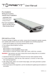
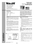
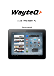
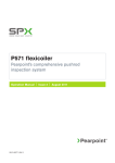
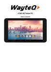
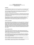
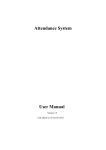
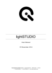
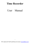
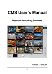
ICubeC User’s Manual
Document Number : MN-ICC 0500
Revision Date:
20 October, 2008
© VisionXtreme Pte Ltd
Singapore 339416
www.vxgp.com
Blk 25 Kallang Ave #06-04 Kallang Basin Industrial Estate Singapore 339416 Tel: (65) 6392 0900 Fax: (65) 6392 2103 Company Registration No.:
200104387H
Table of Contents
Table of Contents
1 Introduction ...........................................................................................................4
1.1
Performance and Specification.................................................................................4
1.2
Mechanical Specifications.........................................................................................5
1.2.1
1.3
ICubeC Dimensions.............................................................................................5
Environmental Requirements....................................................................................6
1.3.1
Temperature and Humidity...................................................................................6
1.3.2
Ventilation ............................................................................................................6
1.4
Precautions.................................................................................................................6
1.4.1
Input Power..........................................................................................................6
1.4.2
Transportation......................................................................................................6
1.4.3
Warranty precautions...........................................................................................6
2 ICubeC Physical Interface .........................................................................7
2.1
General Description ...................................................................................................7
2.2
Connector Details.......................................................................................................7
2.3
Pin Assignments ........................................................................................................7
2.3.1
USB Interface connector......................................................................................7
2.3.2
15-pin D-Sub Connector ......................................................................................8
2.3.3
44-pin D-Sub connector.......................................................................................9
2.3.4
Power Supply Connector ...................................................................................10
2.4
Cable Drawings ........................................................................................................11
2.4.1
Power Supply Cable .......................................................................................... 11
2.4.2
USB Cable ......................................................................................................... 11
2.4.3
Control Cable.....................................................................................................12
2.4.4
Lighthead Interface ............................................................................................13
3 Hardware and Software Installation................................................14
3.1
Requirements.............................................................................................................14
3.2
Software Installation ...................................................................................................14
3.3
Hardware Installation..................................................................................................17
ICubeC User’s Manual
2
Table of Contents
4 Operations and Features .........................................................................18
4.1
Device Selection.......................................................................................................18
4.2
Controllers and Channels........................................................................................20
4.3
Other Features..........................................................................................................22
4.3.1
Strobe Pulse width and Intensity variation .........................................................22
4.3.2
Strobe Source and Edge selection.....................................................................23
4.3.3
Strobe Delay Selection ......................................................................................26
4.3.4
Saving/Loading multiple configurations .............................................................27
4.4
Steps to be followed for configuring ICubeC.........................................................28
ICubeC User’s Manual
3
1Introduction
1 Introduction
The ICubeC programmable illumination controller allows users to set different intensities and
patterns to highlight defects on various types of objects. With ability to switch light intensity and
patterns at high speed, multiple images of the same device can be captured under different light
conditions, to highlight a variety of defects. On board flash memory enables multiple parameter files
to be stored for easy retrieval in the event of power loss.
1.1
Performance and Specification
Category
Specification
Power Requirements
+24VDC @5A max (32-Segments)
Current Consumption
220 mA (Max) per segment
Host Interface
USB1.1 or USB 2.0
Strobe Pulse Time
Programmable via API (Configurable from 1 to 10 msec)
External Trigger
2 (Software Programmable Segments)
Onboard Flash Memory
8K bytes (Max)
Camera Trigger Delay
Programmable in 3 steps
Dimension
115 mm (L) x 105 mm (W) X 34 mm (H)
Weight
380 GMS
Table 1.1: Performance Specifications of ICubeC
ICubeC User’s Manual
4
1Introduction
1.2
Mechanical Specifications
1.2.1 ICubeC Dimensions
Figure 1.1: ICubeC Mechanical Dimension
ICubeC User’s Manual
5
1Introduction
1.3
Environmental Requirements
1.3.1 Temperature and Humidity
Housing temperature during operation:
0° C … + 50° C (+ 32° F … +122° F)
Storage temperature:
- 20° C … + 80° C (-4° F … +176° F)
Humidity during operation:
20% … 80% relative, without condensation
Storage humidity:
20% … 80% relative, without condensation
1.3.2 Ventilation
The ICubeC housing is provided with Ventilation Fan so as to maintain the temperature
40ºC during operation. Proper Heat Sinks are to be provided.
1.4
below
Precautions
Read the ICubeC user’s manual carefully before using the product
1.4.1 Input Power
Reversing of the polarity of the input power to the ICubeC connector will damage it.
1.4.2 Transportation
Transportation of the product should be done in the same packaging.
1.4.3 Warranty precautions
•
Opening the casing
Do not open the casing. If the product is disassembled, reworked or repaired by other than
recommended service person, we will not take the responsibility of any subsequent
malfunctioning of the product.
•
Keep out of foreign matters
Be careful not to allow liquid, flammable, or metallic material inside the housing. If operated
with any foreign matter inside, the ICubeC may fail or malfunction
ICubeC User’s Manual
6
2 ICubeC Physical Interface
2 ICubeC Physical Interface
This section provides the detailed information on connector pin-out, physical interface and voltage
requirements for ICubeC.
2.1
General Description
ICubeC is interfaced to PC via the USB port and to camera via 15-pin D-Sub connector. It connects
to the 32 Segment Light via 44-pin connector.
2.2
Connector Details
There are totally four connectors in ICubeC.
•
USB interface Connector for Control Signals
•
15-pin D-Sub Connector [Female, Right angle] for Strobe/Trigger Signal
•
DC Power socket for power supply
•
44-pin connector [3-row, Female, Right angle] for Light Head Connection
The different connector views are shown in the below figures
Fig 2.1: Front view of ICubeC
Fig 2.2: 44-pin connector Rear view of ICubeC
2.3
Pin Assignments
2.3.1 USB Interface connector
The USB Interface Connector is used for communicating ICubeC with PC to provide control signals
and data to the ICubeC from PC. The Pin numbering is shown in the below diagram.
Corresponding Pin assignment is shown in Table 2.1
ICubeC User’s Manual
7
2 ICubeC Physical Interface
USB Connector
Signal Description
1
+5 VDC
2
Data -
3
Data +
4
GND
Table 2.1: Pin-out of USB Connector
2.3.2 15-pin D-Sub Connector
This connector is used for interfacing the trigger and strobe signal from/to camera according to
requirement. Following is the pin-out for the 15-pin control connector. The Pin numbering is shown
in the below diagram. Corresponding Pin assignment is shown in table 2.2
15-pin Connector Pin
Signal Description
1
Trigger 1
2
Trigger 3
3
Camera Strobe 1
4
Camera Strobe 3
5
Reserved
6
GND
7
GND
8
GND
9
Trigger 2
ICubeC User’s Manual
8
2 ICubeC Physical Interface
10
Trigger 4
11
Camera Strobe 2
12
Camera Strobe 4
13
Reserved
14
GND
15
GND
Table 2.2: Pin-out of Control Connector
2.3.3 44-pin D-Sub connector
The 44-Pin connector of ICubeC is used to provide the light intensity output from ICubeC to the 32segment Lighthead. The Pin numbering is shown in the below diagram. Corresponding Pin
assignments for the 44-pin connector are shown in Table 2.3
44-pin Connector Pin
Signal Description
1
+24V
2
Output 1
3
Output 2
4
Output 3
5
Output 4
6
Output 5
7
Output 6
8
Output 7
9
Output 8
10
+24V
11
Output 9
12
Output 10
13
Output 11
14
Output 12
ICubeC User’s Manual
9
2 ICubeC Physical Interface
15
Output 13
16
Output 14
17
Output 15
18
Output 16
19
Output 17
20
Output 18
21
Output 19
22
Output 20
23
Output 21
24
Output 22
25
Output 23
26
Output 24
27
Output 25
28
Output 26
29
Output 27
30
Output 28
31
Output 29
32
Output 30
33
Output 31
34
Output 32
35-44
NA
Table 2.3: Pin-out of Lighthead connector.
2.3.4 Power Supply Connector
The power requirement of ICubeC is +24VDC 5.3A. The Pin numbering is shown in the below
diagram.
Table 2.4 shows the pin assignments of the DC power supply connector.
DC Power Connector
1
Signal Description
2
GND
+24VDC
Table 2.4: Pin-out of DC Power Connector
ICubeC User’s Manual
10
2 ICubeC Physical Interface
2.4
Cable Drawings
2.4.1 Power Supply Cable
To DC Power Connector
From +24V Supply
1
+24VDC
2
GND
DC Power Cable
Receptacle
From +24V
Power Supply
Fig 2.3: Power Supply Cable
2.4.2 USB Cable
To iCubeC
To PC
Fig 2.4: USB Cable
ICubeC User’s Manual
11
2 ICubeC Physical Interface
2.4.3 Control Cable
To 15-pin D-Sub Female
Connector of ICubeC
1
2
3
4
To 15-pin D-Sub Male
Connector of Camera I/O
Trigger 1
Trigger 3
1
2
Camera Strobe 1
3
Camera Strobe 3
4
9
Trigger 2
9
10
Trigger 4
10
11
12
6, 7, 8,
14, 15
15-Pin D-sub Male
(To 15-pin D-sub
Control Connector)
Camera Strobe 2
11
Camera Strobe 4
12
GND
6, 7, 8,
14, 15
15-Pin D-sub Female
(To Camera I/O
Connector)
Fig 2.5: Control Cable
ICubeC User’s Manual
12
2 ICubeC Physical Interface
2.4.4 Lighthead Interface
To 44-pin Lighthead Connector
32-segment Light
+ 24VDC
1, 10
1,10
OUTPUT
2 to 9
2 to 9
OUTPUT
11 to 34
11 to 34
32 segment Light
44-Pin Male
(To 44-pin Lighthead
Connector)
Fig 2.6: Lighthead Cable
LED Electrical Circuitry
The lighthead can be designed according to any of the following LED connectivity options. Few
sample circuits are shown below
+ 24VDC
+ 24VDC
OR
OUTPUT
ICubeC User’s Manual
OUTPUT
+ 24VDC
OR
OUTPUT
13
3 Hardware and Software Installation
3
Hardware and Software Installation
This section provides the initial hardware and software installation procedures to work with ICubeC
3.1
Requirements
Following are the required hardware and software components to start the installation
1. ICubeC Device
2. Power Supply
A power supply of +24VDC is required for powering the ICubeC
3. Interfacing cables
ICubeC requires 3 types of cables (Power Supply Cable, Master Cable and USB Cable) that
comes with package
4. Software package
The Software package includes necessary files to install the API and driver. The application can
run in Windows 2000, Windows XP platforms
3.2
Software Installation
This section explains in detail about the software installation of lighting controller using the setup
file provided with the installation disk. Follow the steps below to install the API.
1. Double click the setup file and run
ICubeC User’s Manual
14
3 Hardware and Software Installation
2. The following LightController setup wizard opens. Click Next button to continue the setup
3. Choose the folder you want to install.
ICubeC User’s Manual
15
3 Hardware and Software Installation
4. Click Next to start installation.
5. Click Close the complete the installation
ICubeC User’s Manual
16
3 Hardware and Software Installation
6. You can see the LightController shortcut icon automatically created in the desktop
To start working with LightController, double click on the icon.
3.3
Hardware Installation
•
Plug in power cable into the DC Power connector of ICubeC
•
Connect the Master cable from camera to the Master connector of ICubeC
•
Connect the USB cable from PC USB port to the ICubeC. Check whether the device is
detected under the Jungo folder in Device Manager (E.g. ICubeC). This indicates the
device is detected.
•
Connect the lighthead to the other end of the ICubeC
ICubeC User’s Manual
17
4 Operations and Features
4
Operations and Features
This chapter explains the basic operations and features of ICubeC. This section also explains the
configuration in detail.
4.1
Device Selection
The application for ICubeC runs either in Windows 2000, Windows NT or Windows XP Platforms.
This section explains the configuration of various light patterns intensity levels using the API
provided. Figure 4.1 shows the appearance of ICubeC application.
Fig. 4.1: The LightController API
Once the application is opened, ensure “ICubeC” is selected under device. If not click on the box
as shown in Fig.4.2
ICubeC User’s Manual
18
4 Operations and Features
Fig. 4.2: ICubeC Device Selection
If there is no ICubeC device connected to the PC, a message box pops up as shown in Fig.4.3
Fig. 4.3: ICubeC Device not detected or connected
ICubeC User’s Manual
19
4 Operations and Features
4.2
Controllers and Channels
There are 4 Channels namely Channel 1, Channel 2, Channel 3 and Channel 4 per Controller. For
example the channels for Controller 2 are shown in Figure 4.4. Similarly, there are 8 Controllers
namely Controller 1, Controller 2, Controller 3, Controller 4, Controller 5, Controller 6, Controller 7
and Controller 8 as shown in Fig.4.4.
Controllers
Channels
Fig.4.4: Channels and Controllers for 32 Segment Light Head
There are 32 segments in ICubeC, which can be controlled individually. To control all the 32
segments, enter ‘31’ in the text box shown in fig. 4.5 under segment selection – Trigger 1 and
select Trigger ‘1’ as shown in the fig. 4.5. If Trigger ‘2’ is selected, any number of segments less
than 16 has to be entered for Trigger ‘1’ and the remaining segments will automatically be assigned
for Trigger ‘2’. One example is shown in fig. 4.6.
ICubeC User’s Manual
20
4 Operations and Features
Fig.4.5: 32 Segments selection for Trigger 1
Fig.4.6: Segments selection for Trigger 2
ICubeC User’s Manual
21
4 Operations and Features
4.3
Other Features
4.3.1 Strobe Pulse width and Intensity variation
This feature is provided to vary the pulse width of the strobe output from ICubeC with respect to the
Trigger from camera or internal strobe. The strobe output of ICubeC decides the Turn on time of the
light. The pulse width of the strobe output from ICubeC should be less than the pulse repetition
period of the camera strobe signal.
Fig. 4.7: Pulse width variation
User can also adjust the intensity variation for the selected segments. The intensity can be varied from 0
to 63 as shown in fig.4.8
ICubeC User’s Manual
22
4 Operations and Features
Fig. 4.8: Light Intensity variation
4.3.2 Strobe Source and Edge selection
External: Select “External “from the Strobe Selection option box. In this case, triggers have to be
sent from the external 9-pin D Type connector to the Trigger 1 pin. Note that the input trigger
voltage from at maximum of 5 Volts and the frequency should be limited to maximum of 10
pulses/sec. External control maybe used for connecting to a camera to a frame grabber output pin
depending upon the requirement.
ICubeC User’s Manual
23
4 Operations and Features
Fig. 4.9: Strobe source Selection
Software: When “Software” strobe source is selected, the “Trigger” button is visible. Clicking on
this button once will send a software strobe to the device.
ICubeC User’s Manual
24
4 Operations and Features
Fig. 4.10: Software strobe from API
Internal: “Internal” is used or Diagnostics purpose only.
(Note: Any frequency higher than 10 pulses/sec will damage the controller)
Select “Rising” from the Trigger 1 Edge Select option box. Take note: It can also be falling edge
depending on your current interface. The purpose of this edge selection to enable the user to
synchronies the input trigger to either of the edges. This is usually required when different
configurations of sensors are used. For e.g. If Trigger 1 is triggered at the “Rising edge” and if you
see a faint and no image at all from the camera, then try setting the edge to “Falling edge”. Note
that the illumination controller has option to connect to 2 lightheads and there fore there is an
option to control the edges for both Trigger 1 and Trigger 2.
ICubeC User’s Manual
25
4 Operations and Features
Fig. 4.11: Strobe Edge Selection
Now the Light head that is connected to the ICubeC starts blinking with the selected pulse width
and intensity, provided an external trigger has been connected to the 9-pin connector. If user does
not see any flashing, try selecting internal strobe
4.3.3 Strobe Delay Selection
The ICubeC offers an option to trigger the camera. This is provided to ensure that the Light
intensity has reached the saturation point before the camera is exposed. More consistent and clear
images are acquired using this method. In the event, you want the ICubeC to send strobe signal to
camera then select a delay 0 / 50us / 100us under STROBE DELAY option. Example: 50us is
selected at the “Strobe Delay” option box. What this means is that the light will first turn ON and
after a delay of 50 ns, a signal to send to the camera via the CAMERA STROBE signal available 9
PIN D TYPE connector.
ICubeC User’s Manual
26
4 Operations and Features
Fig. 4.12: Strobe Delay Selection
4.3.4 Saving/Loading multiple configurations
Save and Load Configuration features are includes in the API for strong multiple configurations and
loading the configuration on to the ICubeC for quick setup.
Save Configuration:
This option is provided to save the light configuration settings. Number of configuration files saved
depends on the hard disk capacity.
Load Configuration:
This option is provided to load the saved configuration settings on to the ICubeC. Pre-stored files
can be reloaded for quick setup.
Exit:
This option is provided to close the ICubeC application.
ICubeC User’s Manual
27
4 Operations and Features
4.4
Steps to be followed for configuring ICubeC
Step 1: ICubeC Address Selection
If more than one ICubeC is used then, the first requirement is to select the ICubeC, which is
supposed to be configured. Selection of ICubeC3 is shown in fig.4.13
Fig. 4.13: ICubeC Address selection
Step 2: Light Segment Selection
Choose the configuration style from below, and then follow the steps given with respect to the
required configuration style.
Configuration Styles:
• Selection of all lights.
• Selection of individual light or group of lights.
(a) Selection of all lights:
• All lights (i.e. all controllers and channels) are selected by simply clicking the box as
shown in figure 4.14.
• The intensity value at selection is zero.
ICubeC User’s Manual
28
4 Operations and Features
Fig 4.14: Selection of all lights
ICubeC User’s Manual
29
4 Operations and Features
(b) Selection of individual light segment:
Select the light segment required to be configured as shown in figure 4.15. For example Controller
3,Channel 1 is selected in figure 4.15.
Fig 4.15: Selection of Individual light segment (Controller 2,Channel 0)
(c) Selection of Group of Lights:
•
•
If the requirement is that all the controllers are to be selected for a particular Channel, then
click the corresponding button number of controller for that channel. Refer Fig.4.16.
If the requirement is that all the channels are to be selected for a particular Controller, then
click the corresponding button number of channel for that controller. Refer Fig.4.17
ICubeC User’s Manual
30
4 Operations and Features
Fig 4.16: Selecting all controllers of channel 2
Fig 4.17: Selecting all channels of Controller 3
ICubeC User’s Manual
31
4 Operations and Features
Step 3: Light Intensity Selection:
• Light Intensity value can be varied from 0 to 63.The value 0 represents the minimum intensity
and the value 63 represents the maximum intensity.
• The light intensity required to be set could be obtained by moving the cursor between minimum
and maximum value as shown in figure 4.18.
Fig 4.18: Light Intensity value set to 30 for all channels of controller 4
Example: To set maximum intensity value for all light segments, first select all light segments
then move the cursor to intensity value 63. Please refer to figure 4.19 and figure 4.20.
ICubeC User’s Manual
32
4 Operations and Features
Fig 4.19: All light segments are selected.
Fig 4.20: Intensity value is set to 63
ICubeC User’s Manual
33
4 Operations and Features
Other method to Switch on all light segments with maximum intensity:
All Light segments can be switched on at one time to a maximum intensity by clicking the “Switch
On” button without selection of any controller and channel as shown in figure 4.21.
It can be switched off by clicking the “Switch Off” button.
Fig 4.21: All light segments switched on to maximum intensity
If different Light intensity values are set for different controllers and channels and if the requirement
is such that all the intensity values of the controllers and channels needs to be increased uniformly
in steps of one, then it could be implemented using the Up and Down arrow buttons in keyboard.
Example: Consider controller 1 is set to intensity value 10, controller 2 is set to 20, controller 3 is
set to 30 and controller 4 is set to 40, then by clicking the Up arrow once, the intensity value of the
controllers will get increased uniformly by one i.e., intensity value of controller 0 is set to 11,
controller 1 to 21,controller 2 to 31,controller 3 to 41.To decrease the intensity by one step, use the
Down arrow button.
ICubeC User’s Manual
34
4 Operations and Features
Step 4: Saving the configuration
The entire configuration set can be saved for future usage. The Configuration data can be saved in the
location/ folder, where the ICubeC application is placed or in any other preferred directory. The
configuration data is saved with .pro extension. Figures 4.22 and 4.23 illustrate how to save
configuration.
Fig 4.22: Click the “Save Configuration” Button.
ICubeC User’s Manual
35
4 Operations and Features
Fig 4.23: Select the location where the configuration data is required to be saved.
Note: After setting the light pattern for Bank 0, light pattern for Bank 1 can also be set by
following the steps 1 to 4.
Step 5: Loading the Saved Configuration
The stored configuration can be loaded on to the ICubeC by clicking the “Load Configuration”
button. Figures 4.24 and 4.25 illustrate the loading of the stored configuration on to the ICubeC
ICubeC User’s Manual
36
4 Operations and Features
Fig 4.24: Click the “Load Configuration” button.
ICubeC User’s Manual
37
4 Operations and Features
Fig 4.25: Select the location, which contains the saved configuration.
Then click the “Open” Button, to load the configuration on to the ICubeC.
Note: The above-mentioned steps should be followed for different light configurations as per the
user requirement.
ICubeC User’s Manual
38