1
Test and Measurement
Division
Operating Manual
Baseband Fading Simulator
ABFS
1114.8506.02
Printed in the Federal
Republic of Germany
1114.8564.12-02
1
Supplement to
Operating Manual
Baseband Fading Simulator ABFS
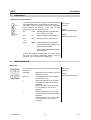
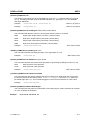
Dear Customer,
Your Baseband Fading Simulator is equipped with a new firmware version. The new firmware offers
the following extensions and improvements:
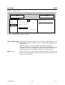
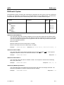
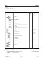
FSIM - FINE DELAY menu:
RF FREQUENCY CH1 Input value of RF frequency of channel 1.
IEC/IEEE-bus command
:SOUR:FSIM:FDEL:CHAN1:RF
100MHz
RF FREQUENCY CH2 Input value of RF frequency of channel 2.
IEC/IEEE-bus command
:SOUR:FSIM:FDEL:CHAN2:RF
100MHz
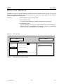
FSIM - MOVING DELAY menu:
RF FREQUENCY
Input value of RF frequency.
IEC/IEEE-bus command
:SOUR:FSIM:MDEL:CHAN:RF
100MHz
FSIM - BIRTH-DEATH menu:
RF FREQUENCY
Input value of RF frequency.
IEC/IEEE-bus command
:SOUR:FSIM:BIRT:CHAN:RF
100MHz
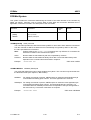
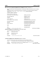
IEC/IEEE-bus commands:
[:SOURce]:FSIMulator:FDELay:CHANnel<1|2>:RF 5.0 MHz ... 8.5 GHz
This command sets the RF frequency of the selected channel in Fine Delay mode. The channel
is selected via the numeric suffix in CHANnel.
Example:
:SOUR:FSIM:FDEL:CHAN1:RF 600 MHz
*RST value is 100 MHz
[:SOURce]:FSIMulator:MDELay:CHANnel:RF 5.0 MHz ... 8.5 GHz
This command sets the RF frequency in Moving Delay mode.
Example:
:SOUR:FSIM:MDEL:CHAN:RF 600 MHz
*RST value is 100 MHz
[:SOURce]:FSIMulator:BIRThdeath:CHANnel:RF 5.0 MHz ... 8.5 GHz
This command sets the RF frequency in Birth-Death mode.
Example:
1114.8564.12
:SOUR:FSIM:BIRT:CHAN:RF 600 MHz
B
*RST value is 100 MHz
E-1
ABFS
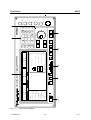
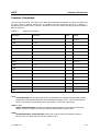
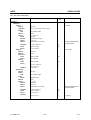
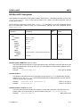
Tabbed Divider Overview
Tabbed Divider Overview
Contents
Data Sheet
Safety Instructions
Certificate of Quality
EC Certificate of Conformity
List of R&S Representatives
General Overview of Manuals
Divider
1
Chapter 1
Preparation for Use
2
Chapter 2
Introduction to Operation
3
Chapter 3
Manual Operation
4
Chapter 4
Functions
5
Chapter 5
Remote Control – Basics
6
Chapter 6
Remote Control – Commands
7
Chapter 7
Remote Control – Programming Examples
8
Chapter 8
Maintenance
9
Chapter 9
Error Messages
10
Chapter 10
Index
1114.8564.12
RE
E-1
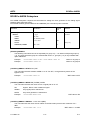
Supplement to Data Sheet ABFS
Enhanced fading functions for WCDMA 3GPP with option ABFSB49
ABFSB49 extends the functionality of the baseband fading simulator ABFS to include WCDMA 3GPP
channel simulation. It adds three new modes to the fading simulator so that all scenarios defined in
3GPP Release 99 can be simulated:
• In fine delay mode, fading simulator resolution is increased to 1 ns with up to four paths being
available.
• In moving delay mode, two paths are simulated: for one path the delay remains constant, whereas
for the other path the delay varies continuously.
• In birth-death mode, there are two paths changing delay in steps in accordance with the 3GPP
channel model.
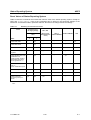
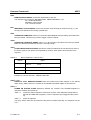
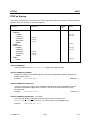
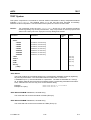
Specifications
The enhanced fading functions for WCDMA 3GPP are only available for the ABFS standard fading
simulator, not for the second fading simulator (option ABFS-B2).
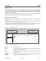
Modes
Setting time after RF frequency change
Standard fading, fine delay, birth-death
6 ms
Fine delay mode
RF banwidth
Number of paths
Profiles
Delay
Delay resolution
4.8 MHz
4
Rayleigh, pure Doppler
25 ns to 1637 µs
1 ns
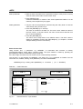
Moving delay mode
RF bandwidth
Number of paths
Delay, path 1
Delay, path 2
4.8 MHz
2
0 to 1000 µs (in 50 ns steps)
delay path1 +
delay variationpk - pk
2
Delay variation (peak-peak)
Variation period
Delay step size
Profiles
150 ns to 50 µs
10 s to 500 s
<1 ns
None
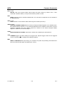
Birth-death mode
Number of paths
Profiles
Delay
Delay range (birth-death process)
Delay grid
Hopping dwell
2
pure Doppler
5 µs to 1000 µs
-5 µs to +5 µs (not variable)
1 µs (not variable)
100 ms to 5 s
⋅ sin
2πt
var iation period
Ordering Information
Enhanced fading functions for WCDMA 3GPP
1114.8564.12
ABFSB49
A
1115.0909.02
E-1
ABFS
Contents
Contents
1 Putting into Operation......................................................................................... 1.1
General Instructions ........................................................................................................................ 1.1
Unpacking the Instrument .............................................................................................................. 1.1
Supply Voltage ................................................................................................................................. 1.1
How to Ensure EMC......................................................................................................................... 1.1
Switching On/Off the Instrument.................................................................................................... 1.2
Initial Status...................................................................................................................................... 1.2
Setting Contrast and Brightness of the Display ........................................................................... 1.2
RAM With Battery Back-Up ............................................................................................................. 1.2
Preset Setting................................................................................................................................... 1.3
Functional Test ................................................................................................................................ 1.3
Mounting into a 19" Rack................................................................................................................ 1.3
Explanation of Front and Rear Panel............................................................................................. 1.5
Elements of the Front Panel .................................................................................................... 1.5
Elements of the Rear Panel................................................................................................... 1.13
2 Brief Introduction ................................................................................................ 2.1
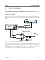
Connection of ABFS ........................................................................................................................ 2.1
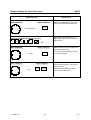
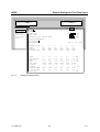
Sample Settings for First-Time Users............................................................................................ 2.2
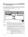
3 Manual Operation ................................................................................................ 3.1
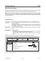
Design of the Display ...................................................................................................................... 3.1
Basic Operating Steps..................................................................................................................... 3.2
Calling the menus .................................................................................................................... 3.2
Selection and Change of Parameters...................................................................................... 3.3
Triggering Action...................................................................................................................... 3.4
Quick Selection of Menu (QUICK SELECT)............................................................................ 3.4
Using Keys [MODE GRP A] and [MODE GRP B].................................................................... 3.4
Using Keys [FADING ON/OFF] and [AWGN ON/OFF] ........................................................... 3.5
Correction of Input ................................................................................................................... 3.5
List Editor ......................................................................................................................................... 3.6
Select and Generate - SELECT LIST ...................................................................................... 3.7
Deletion of Lists - DELETE LIST ............................................................................................. 3.9
Edition of Lists ....................................................................................................................... 3.10
SAVE/RECALL – Storing/Calling of Instrument Settings........................................................... 3.15
Menu Summary .............................................................................................................................. 3.16
1114.8564.12
3
E-2
Contents
ABFS
4 Device Functions................................................................................................. 4.1
Fading Modes................................................................................................................................... 4.1
Basic Units With 12 Paths ....................................................................................................... 4.1
Fading With Option ABFS-B2.................................................................................................. 4.3
Fading Setting Parameters - Correlation Between Paths ........................................................ 4.3
FSIM Menu (without option B49) /STANDARD FAD Menu (with option B49) ......................... 4.5
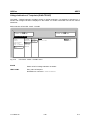
FINE DELAY Menu................................................................................................................ 4.10
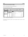
MOVING DELAY Menu ......................................................................................................... 4.12
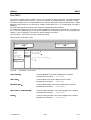
BIRTH-DEATH Menu ............................................................................................................ 4.14
Noise Generator ............................................................................................................................. 4.16
MODE Menu With Built-in Noise Generators Option ABFS-B1 / Option ABFS-B3 .............. 4.17
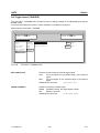
AWGN Menu ......................................................................................................................... 4.19
Calibration ...................................................................................................................................... 4.20
CALIBRATE Menu................................................................................................................. 4.20
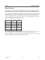
Memory Sequence ......................................................................................................................... 4.21
Modes (MODE)...................................................................................................................... 4.22
External Trigger ..................................................................................................................... 4.22
HOP CONTROL .............................................................................................................................. 4.25
HOP CONTROL Without Trigger Control.............................................................................. 4.26
HOP CONTROL With Trigger Control................................................................................... 4.27
HOP CONTROL Menu .......................................................................................................... 4.28
Utilities ............................................................................................................................................ 4.31
IEC/IEEE-Bus Address (SYSTEM - GPIB) ............................................................................ 4.31
Parameter of RS-232-C Interface (SYSTEM - RS232) ......................................................... 4.32
Display of IEC/IEEE-Bus Language ...................................................................................... 4.33
Password Entry With Protected Functions (PROTECT) ....................................................... 4.34
Display of Module Versions (DIAG-CONFIG)........................................................................ 4.35
Voltage Indication of Testpoints (DIAG-TPOINT).................................................................. 4.36
Indication of Service Data (DIAG - PARAM) ......................................................................... 4.37
Test (TEST) ........................................................................................................................... 4.38
Set Trigger Inputs (TRIGGER) .............................................................................................. 4.39
Switch On/Off of Beeper........................................................................................................ 4.40
Help System ................................................................................................................................... 4.41
Status .............................................................................................................................................. 4.42
5 Remote Control - Basic Information .................................................................. 5.1
Brief Instructions ............................................................................................................................. 5.1
IEC/IEEE Bus .......................................................................................................................... 5.1
RS-232-C Interface.................................................................................................................. 5.2
Switchover to Remote Control ....................................................................................................... 5.3
Remote Control via IEC/IEEE Bus........................................................................................... 5.3
Setting the Device Address......................................................................................... 5.3
Indications during Remote Control ............................................................................. 5.3
Return to Manual Operation........................................................................................ 5.4
Remote Control via RS-232-C Interface.................................................................................. 5.4
Setting the Transmission Parameters ........................................................................ 5.4
Indications during Remote Control ............................................................................. 5.4
Return to Manual Operation........................................................................................ 5.4
1114.8564.12
4
E-2
ABFS
Contents
Messages.......................................................................................................................................... 5.5
Interface Messages ................................................................................................................. 5.5
Device Messages (Commands and Device Responses) ........................................................ 5.5
Structure and Syntax of Device Messages ................................................................................... 5.6
Introduction to SCPI................................................................................................................. 5.6
Structure of Commands .......................................................................................................... 5.6
Structure of Command Lines................................................................................................... 5.9
Responses to Queries ............................................................................................................. 5.9
Parameters ............................................................................................................................ 5.10
Overview of Syntax Elements................................................................................................ 5.12
Instrument Model and Command Processing ............................................................................ 5.13
Input Unit ............................................................................................................................... 5.13
Command Recognition .......................................................................................................... 5.14
Data Set and Instrument Hardware ....................................................................................... 5.14
Status Reporting System ....................................................................................................... 5.14
Output Unit............................................................................................................................. 5.15
Command Sequence and Command Synchronization.......................................................... 5.15
Status Reporting System .............................................................................................................. 5.16
Structure of an SCPI Status Register .................................................................................... 5.16
Overview of Status Registers ................................................................................................ 5.18
Description of Status Registers ............................................................................................. 5.19
Status Byte (STB) and Service Request Enable Register (SRE) ............................. 5.19
IST Flag and Parallel Poll Enable Register (PPE) .................................................... 5.20
Event Status Register (ESR) and Event Status Enable Register (ESE)................... 5.20
STATus:OPERation Register ................................................................................... 5.21
STATus:QUEStionable Register............................................................................... 5.21
Use of Status Reporting System ........................................................................................... 5.22
Service Request, Making Use of Hierarchy Structure .............................................. 5.22
Serial Poll 5.22
Parallel Poll ............................................................................................................... 5.23
Query by Means of Commands ................................................................................ 5.23
Error Queue Query ................................................................................................... 5.23
Reset Values of Status Reporting System ............................................................................ 5.24
Interfaces ........................................................................................................................................ 5.25
IEC/IEEE-Bus Interface ......................................................................................................... 5.25
Characteristics of Interface ....................................................................................... 5.25
Bus Lines 5.25
Interface Functions ................................................................................................... 5.26
Interface Messages .................................................................................................. 5.27
RS-232-C Interface................................................................................................................ 5.28
Characteristics of Interface ....................................................................................... 5.28
Signal Lines .............................................................................................................. 5.28
Transmission Parameters......................................................................................... 5.29
Interface Functions ................................................................................................... 5.29
Handshake................................................................................................................ 5.30
1114.8564.12
5
E-2
Contents
ABFS
6 Remote Control – Command Description ......................................................... 6.1
Notation ............................................................................................................................................ 6.1
Common Commands....................................................................................................................... 6.3
ABORt System.................................................................................................................................. 6.6
CALibration System......................................................................................................................... 6.7
DIAGnostic System.......................................................................................................................... 6.9
FORMat System ............................................................................................................................. 6.10
SOURCe:AWGN Subsystem ......................................................................................................... 6.11
SOURce:FSIM Subsystem............................................................................................................. 6.13
SOURce:HOP Subsystem ............................................................................................................. 6.26
STATus System.............................................................................................................................. 6.28
SYSTem System............................................................................................................................. 6.31
TEST System .................................................................................................................................. 6.37
TRIGger System ............................................................................................................................. 6.39
Command List ................................................................................................................................ 6.41
7 Remote Control - Programming Examples ....................................................... 7.1
Including IEC-Bus Library for QuickBasic .................................................................................... 7.1
Initialization and Default Status ..................................................................................................... 7.1
Initiate Controller...................................................................................................................... 7.1
Initiate Instrument .................................................................................................................... 7.1
Transmission of Instrument Setting Commands ......................................................................... 7.2
Switchover to Manual Control ........................................................................................................ 7.2
Reading out Instrument Settings ................................................................................................... 7.2
List Management ............................................................................................................................. 7.3
Command synchronization............................................................................................................. 7.3
Service Request ............................................................................................................................... 7.4
8 Maintenance......................................................................................................... 8.1
Cleaning the Outside ....................................................................................................................... 8.1
Storing and Packing ........................................................................................................................ 8.1
9 Error Messages ................................................................................................... 9.1
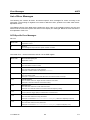
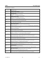
List of Error Messages .................................................................................................................... 9.2
SCPI-Specific Error Messages ................................................................................................ 9.2
ABFS- Specific Error Messages .............................................................................................. 9.6
10Index ................................................................................................................... 10.1
1114.8564.12
6
E-2
ABFS
Contents
Tables
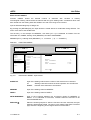
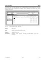
Table 4-1
Possible combinations of options with basic ABFS unit ...............................................4.17
Table 4-2
Memory sequence; example of a list............................................................................4.21
Table 5-1
Synchronization by means of *OPC, *OPC? and *WAI................................................5.15
Table 5-2
Meaning of the bits used in the status byte ..................................................................5.19
Table 5-3
Meaning of the bits used in the event status register ...................................................5.20
Table 5-4
Meaning of the bits used in the STATus:OPERation register ......................................5.21
Table 5-5
Meaning of the bits used in the STATus:QUEStionable register..................................5.21
Table 5-6
Resetting of instrument functions .................................................................................5.24
Table 5-7
Interface functions ........................................................................................................5.26
Table 5-8
Universal commands....................................................................................................5.27
Table 5-9
Addressed commands .................................................................................................5.27
Table 5-10
Control characters for RS-232-C interface...................................................................5.29
Table 6-1
Common Commands .....................................................................................................6.3
Table 6-2
Device response in case of OPT?..................................................................................6.4
1114.8564.12
7
E-2
Contents
ABFS
Figures
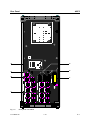
Fig. 1-1
Front panel view ABFS ....................................................................................................... 1.4
Fig. 1-2
Rear panel view ABFS...................................................................................................... 1.12
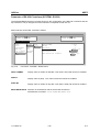
Fig. 2-1
Connection of Fading Simulator ABFS............................................................................... 2.1
Fig. 2-2
Signal input/outputs on rear panel of ABFS ....................................................................... 2.2
Fig. 2-3
Display for setting the fading mode .................................................................................... 2.3
Fig. 2-4
Display for setting fading .................................................................................................... 2.5
Fig. 3-1
Design of the display .......................................................................................................... 3.1
Fig. 3-2
Fading setting menu ........................................................................................................... 3.2
Fig. 3-3
OPERATION page of the MEM SEQ menu ....................................................................... 3.6
Fig. 3-4
SELECT-LIST selection window......................................................................................... 3.8
Fig. 3-5
DELETE-LIST selection window......................................................................................... 3.9
Fig. 3-6
Edit function EDIT/VIEW .................................................................................................. 3.10
Fig. 3-7
Edit function FILL: input window....................................................................................... 3.11
Fig. 3-8
Edit function INSERT: input window................................................................................. 3.13
Fig. 3-9
Edit function DELETE: input window ................................................................................ 3.14
Fig. 4-1
Selection of operating modes in MODE submenu ............................................................. 4.1
Fig. 4-2
Display of signal paths in the MODE submenu .................................................................. 4.2
Fig. 4-3
MODE submenu with built-in option ABFS-B2 ................................................................... 4.3
Fig. 4-4
FSIM selection menu with option B49 (option ABFS-B2 not installed)............................... 4.4
Fig. 4-5
FSIM menu (without ABFS-B49 and without ABFS-B2) / STANDARD FAD menu (with
ABFS-B49) ......................................................................................................................... 4.5
Fig. 4-6
Doppler frequency shift with moving receiver..................................................................... 4.8
Fig. 4-7
FINE DELAY menu........................................................................................................... 4.10
Fig. 4-8
MOVING DELAY .............................................................................................................. 4.12
Fig. 4-9
Example of hopping sequence with BIRTH-DEATH fading.............................................. 4.14
Fig. 4-10
BIRTH-DEATH menu ....................................................................................................... 4.14
Fig. 4-11
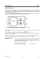
Block diagram of fading simulator with integral noise generator ...................................... 4.16
Fig. 4-12
MODE menu (option ABFS-B1 installed) ......................................................................... 4.17
Fig. 4-13
MODE menu (options ABFS-B1 / ABFS-B2 installed)...................................................... 4.18
Fig. 4-14
MODE menu (options ABFS-B1 / ABFS-B2 / ABFS-B3 installed).................................... 4.18
Fig. 4-15
AWGN menu .................................................................................................................... 4.19
Fig. 4-16
CALIBRATE menu............................................................................................................ 4.20
Fig. 4-17
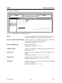
MEM SEQ menu, OPERATION page .............................................................................. 4.23
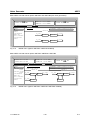
Fig. 4-18
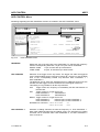
MEM SEQ menu, EDIT page ........................................................................................... 4.24
Fig. 4-19
Timing diagram during HOP CONTROL without trigger control....................................... 4.26
Fig. 4-20
Timing diagram during HOP CONTROL with trigger control............................................ 4.27
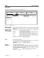
Fig. 4-21
HOP CONTROL menu ..................................................................................................... 4.28
Fig. 4-22
HOP CONTROL menu, EDIT page.................................................................................. 4.30
Fig. 4-23
UTILITIES - SYSTEM – GPIB menu ................................................................................ 4.31
Fig. 4-24
UTILITIES - SYSTEM – RS232 menu.............................................................................. 4.32
Fig. 4-25
UTILITIES - PROTECT menu (preset settings) ............................................................... 4.34
Fig. 4-26
UTILITIES - DIAG – CONFIG menu................................................................................. 4.35
1114.8564.12
8
E-2
ABFS
Contents
Fig. 4-27
UTILITIES - DIAG – TPOINT menu ................................................................................. 4.36
Fig. 4-28
UTILITIES - DIAG – PARAM menu.................................................................................. 4.37
Fig. 4-29
UTILITIES – TEST menu ................................................................................................. 4.38
Fig. 4-30
UTILITIES – TRIGGER menu .......................................................................................... 4.39
Fig. 4-31
UTILITIES – BEEPER menu ............................................................................................ 4.40
Fig. 4-32
STATUS page .................................................................................................................. 4.42
Fig. 5-1
Tree structure of SCPI command systems using the SOURce system as an example..... 5.7
Fig. 5-2
Device model for remote control via the IEC/IEEE bus.................................................... 5.13
Fig. 5-3
Status register model........................................................................................................ 5.16
Fig. 5-4
Overview of status registers ............................................................................................. 5.18
Fig. 5-5
Pin assignment of IEC/IEEE-bus interface....................................................................... 5.25
Fig. 5-6
Pin assignment of RS-232-C interface ............................................................................. 5.28
Fig. 5-7
Wiring of data, control and signalling lines for hardware handshake ............................... 5.30
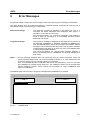
Fig. 9-1
ERROR page...................................................................................................................... 9.1
1114.8564.12
9
E-2
Before putting the product into operation for
the first time, make sure to read the following
Safety Instructions
Rohde & Schwarz makes every effort to keep the safety standard of its products up to date and to offer
its customers the highest possible degree of safety. Our products and the auxiliary equipment required
for them are designed and tested in accordance with the relevant safety standards. Compliance with
these standards is continuously monitored by our quality assurance system. This product has been
designed and tested in accordance with the EC Certificate of Conformity and has left the manufacturer’s
plant in a condition fully complying with safety standards. To maintain this condition and to ensure safe
operation, observe all instructions and warnings provided in this manual. If you have any questions
regarding these safety instructions, Rohde & Schwarz will be happy to answer them.
Furthermore, it is your responsibility to use the product in an appropriate manner. This product is
designed for use solely in industrial and laboratory environments or in the field and must not be used in
any way that may cause personal injury or property damage. You are responsible if the product is used
for an intention other than its designated purpose or in disregard of the manufacturer's instructions. The
manufacturer shall assume no responsibility for such use of the product.
The product is used for its designated purpose if it is used in accordance with its operating manual and
within its performance limits (see data sheet, documentation, the following safety instructions). Using
the products requires technical skills and knowledge of English. It is therefore essential that the
products be used exclusively by skilled and specialized staff or thoroughly trained personnel with the
required skills. If personal safety gear is required for using Rohde & Schwarz products, this will be
indicated at the appropriate place in the product documentation.
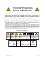
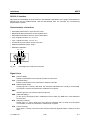
Symbols and safety labels
Observe
operating
instructions
Weight
indication for
units >18 kg
Supply
voltage
ON/OFF
1171.0000.42-02.00
Danger of
electric
shock
Standby
indication
Direct
current
(DC)
Warning!
Hot
surface
PE terminal
Alternating
current (AC)
Ground
Direct/alternating
current (DC/AC)
Ground
terminal
Attention!
Electrostatic
sensitive
devices
Device fully
protected by
double/reinforced
insulation
Sheet 1
Safety Instructions
Observing the safety instructions will help prevent personal injury or damage of any kind caused by
dangerous situations. Therefore, carefully read through and adhere to the following safety instructions
before putting the product into operation. It is also absolutely essential to observe the additional safety
instructions on personal safety that appear in other parts of the documentation. In these safety
instructions, the word "product" refers to all merchandise sold and distributed by Rohde & Schwarz,
including instruments, systems and all accessories.
Tags and their meaning
DANGER
This tag indicates a safety hazard with a high potential of risk for the
user that can result in death or serious injuries.
WARNING
This tag indicates a safety hazard with a medium potential of risk for the
user that can result in death or serious injuries.
CAUTION
This tag indicates a safety hazard with a low potential of risk for the user
that can result in slight or minor injuries.
ATTENTION
This tag indicates the possibility of incorrect use that can cause damage
to the product.
NOTE
This tag indicates a situation where the user should pay special attention
to operating the product but which does not lead to damage.
These tags are in accordance with the standard definition for civil applications in the European
Economic Area. Definitions that deviate from the standard definition may also exist. It is therefore
essential to make sure that the tags described here are always used only in connection with the
associated documentation and the associated product. The use of tags in connection with unassociated
products or unassociated documentation can result in misinterpretations and thus contribute to personal
injury or material damage.
Basic safety instructions
1. The product may be operated only under
the operating conditions and in the
positions specified by the manufacturer. Its
ventilation must not be obstructed during
operation. Unless otherwise specified, the
following requirements apply to
Rohde & Schwarz products:
prescribed operating position is always with
the housing floor facing down, IP protection
2X, pollution severity 2, overvoltage
category 2, use only in enclosed spaces,
max. operation altitude max. 2000 m.
Unless specified otherwise in the data
sheet, a tolerance of ±10% shall apply to
the nominal voltage and of ±5% to the
nominal frequency.
2. Applicable local or national safety
regulations and rules for the prevention of
accidents must be observed in all work
performed. The product may be opened
only by authorized, specially trained
personnel. Prior to performing any work on
the product or opening the product, the
1171.0000.42-02.00
product must be disconnected from the
supply network. Any adjustments,
replacements of parts, maintenance or
repair must be carried out only by technical
personnel authorized by Rohde & Schwarz.
Only original parts may be used for
replacing parts relevant to safety (e.g.
power switches, power transformers,
fuses). A safety test must always be
performed after parts relevant to safety
have been replaced (visual inspection, PE
conductor test, insulation resistance
measurement, leakage current
measurement, functional test).
3. As with all industrially manufactured goods,
the use of substances that induce an
allergic reaction (allergens, e.g. nickel)
such as aluminum cannot be generally
excluded. If you develop an allergic
reaction (such as a skin rash, frequent
sneezing, red eyes or respiratory
difficulties), consult a physician immediately
to determine the cause.
Sheet 2
Safety Instructions
4. If products/components are mechanically
and/or thermically processed in a manner
that goes beyond their intended use,
hazardous substances (heavy-metal dust
such as lead, beryllium, nickel) may be
released. For this reason, the product may
only be disassembled, e.g. for disposal
purposes, by specially trained personnel.
Improper disassembly may be hazardous to
your health. National waste disposal
regulations must be observed.
5. If handling the product yields hazardous
substances or fuels that must be disposed
of in a special way, e.g. coolants or engine
oils that must be replenished regularly, the
safety instructions of the manufacturer of
the hazardous substances or fuels and the
applicable regional waste disposal
regulations must be observed. Also
observe the relevant safety instructions in
the product documentation.
6. Depending on the function, certain products
such as RF radio equipment can produce
an elevated level of electromagnetic
radiation. Considering that unborn life
requires increased protection, pregnant
women should be protected by appropriate
measures. Persons with pacemakers may
also be endangered by electromagnetic
radiation. The employer is required to
assess workplaces where there is a special
risk of exposure to radiation and, if
necessary, take measures to avert the
danger.
7. Operating the products requires special
training and intense concentration. Make
certain that persons who use the products
are physically, mentally and emotionally fit
enough to handle operating the products;
otherwise injuries or material damage may
occur. It is the responsibility of the
employer to select suitable personnel for
operating the products.
8. Prior to switching on the product, it must be
ensured that the nominal voltage setting on
the product matches the nominal voltage of
the AC supply network. If a different voltage
is to be set, the power fuse of the product
may have to be changed accordingly.
9. In the case of products of safety class I with
movable power cord and connector,
operation is permitted only on sockets with
earthing contact and protective earth
connection.
1171.0000.42-02.00
10. Intentionally breaking the protective earth
connection either in the feed line or in the
product itself is not permitted. Doing so can
result in the danger of an electric shock
from the product. If extension cords or
connector strips are implemented, they
must be checked on a regular basis to
ensure that they are safe to use.
11. If the product has no power switch for
disconnection from the AC supply, the plug
of the connecting cable is regarded as the
disconnecting device. In such cases, it
must be ensured that the power plug is
easily reachable and accessible at all times
(length of connecting cable approx. 2 m).
Functional or electronic switches are not
suitable for providing disconnection from
the AC supply. If products without power
switches are integrated in racks or systems,
a disconnecting device must be provided at
the system level.
12. Never use the product if the power cable is
damaged. By taking appropriate safety
measures and carefully laying the power
cable, ensure that the cable cannot be
damaged and that no one can be hurt by
e.g. tripping over the cable or suffering an
electric shock.
13. The product may be operated only from
TN/TT supply networks fused with max.
16 A.
14. Do not insert the plug into sockets that are
dusty or dirty. Insert the plug firmly and all
the way into the socket. Otherwise this can
result in sparks, fire and/or injuries.
15. Do not overload any sockets, extension
cords or connector strips; doing so can
cause fire or electric shocks.
16. For measurements in circuits with voltages
Vrms > 30 V, suitable measures (e.g.
appropriate measuring equipment, fusing,
current limiting, electrical separation,
insulation) should be taken to avoid any
hazards.
17. Ensure that the connections with
information technology equipment comply
with IEC 950/EN 60950.
18. Never remove the cover or part of the
housing while you are operating the
product. This will expose circuits and
components and can lead to injuries, fire or
damage to the product.
Sheet 3
Safety Instructions
19. If a product is to be permanently installed,
the connection between the PE terminal on
site and the product's PE conductor must
be made first before any other connection
is made. The product may be installed and
connected only by a skilled electrician.
20. For permanently installed equipment
without built-in fuses, circuit breakers or
similar protective devices, the supply circuit
must be fused in such a way that suitable
protection is provided for users and
products.
21. Do not insert any objects into the openings
in the housing that are not designed for this
purpose. Never pour any liquids onto or into
the housing. This can cause short circuits
inside the product and/or electric shocks,
fire or injuries.
22. Use suitable overvoltage protection to
ensure that no overvoltage (such as that
caused by a thunderstorm) can reach the
product. Otherwise the operating personnel
will be endangered by electric shocks.
23. Rohde & Schwarz products are not
protected against penetration of water,
unless otherwise specified (see also safety
instruction 1.). If this is not taken into
account, there exists the danger of electric
shock or damage to the product, which can
also lead to personal injury.
24. Never use the product under conditions in
which condensation has formed or can form
in or on the product, e.g. if the product was
moved from a cold to a warm environment.
25. Do not close any slots or openings on the
product, since they are necessary for
ventilation and prevent the product from
overheating. Do not place the product on
soft surfaces such as sofas or rugs or
inside a closed housing, unless this is well
ventilated.
26. Do not place the product on heatgenerating devices such as radiators or fan
heaters. The temperature of the
environment must not exceed the maximum
temperature specified in the data sheet.
27. Batteries and storage batteries must not be
exposed to high temperatures or fire. Keep
batteries and storage batteries away from
children. If batteries or storage batteries are
improperly replaced, this can cause an
explosion (warning: lithium cells). Replace
the battery or storage battery only with the
1171.0000.42-02.00
matching Rohde & Schwarz type (see
spare parts list). Batteries and storage
batteries are hazardous waste. Dispose of
them only in specially marked containers.
Observe local regulations regarding waste
disposal. Do not short-circuit batteries or
storage batteries.
28. Please be aware that in the event of a fire,
toxic substances (gases, liquids etc.) that
may be hazardous to your health may
escape from the product.
29. Please be aware of the weight of the
product. Be careful when moving it;
otherwise you may injure your back or other
parts of your body.
30. Do not place the product on surfaces,
vehicles, cabinets or tables that for reasons
of weight or stability are unsuitable for this
purpose. Always follow the manufacturer's
installation instructions when installing the
product and fastening it to objects or
structures (e.g. walls and shelves).
31. Handles on the products are designed
exclusively for personnel to hold or carry
the product. It is therefore not permissible
to use handles for fastening the product to
or on means of transport such as cranes,
fork lifts, wagons, etc. The user is
responsible for securely fastening the
products to or on the means of transport
and for observing the safety regulations of
the manufacturer of the means of transport.
Noncompliance can result in personal injury
or material damage.
32. If you use the product in a vehicle, it is the
sole responsibility of the driver to drive the
vehicle safely. Adequately secure the
product in the vehicle to prevent injuries or
other damage in the event of an accident.
Never use the product in a moving vehicle if
doing so could distract the driver of the
vehicle. The driver is always responsible for
the safety of the vehicle; the manufacturer
assumes no responsibility for accidents or
collisions.
33. If a laser product (e.g. a CD/DVD drive) is
integrated in a Rohde & Schwarz product,
do not use any other settings or functions
than those described in the documentation.
Otherwise this may be hazardous to your
health, since the laser beam can cause
irreversible damage to your eyes. Never try
to take such products apart, and never look
into the laser beam.
Sheet 4
Por favor lea imprescindiblemente antes de
la primera puesta en funcionamiento las
siguientes informaciones de seguridad
Informaciones de seguridad
Es el principio de Rohde & Schwarz de tener a sus productos siempre al día con los estandards de
seguridad y de ofrecer a sus clientes el máximo grado de seguridad. Nuestros productos y todos los
equipos adicionales son siempre fabricados y examinados según las normas de seguridad vigentes.
Nuestra sección de gestión de la seguridad de calidad controla constantemente que sean cumplidas
estas normas. Este producto ha sido fabricado y examinado según el comprobante de conformidad
adjunto según las normas de la CE y ha salido de nuestra planta en estado impecable según los
estandards técnicos de seguridad. Para poder preservar este estado y garantizar un funcionamiento
libre de peligros, deberá el usuario atenerse a todas las informaciones, informaciones de seguridad y
notas de alerta. Rohde&Schwarz está siempre a su disposición en caso de que tengan preguntas
referentes a estas informaciones de seguridad.
Además queda en la responsabilidad del usuario utilizar el producto en la forma debida. Este producto
solamente fue elaborado para ser utilizado en la indústria y el laboratorio o para fines de campo y de
ninguna manera deberá ser utilizado de modo que alguna persona/cosa pueda ser dañada. El uso del
producto fuera de sus fines definidos o despreciando las informaciones de seguridad del fabricante
queda en la responsabilidad del usuario. El fabricante no se hace en ninguna forma responsable de
consecuencias a causa del maluso del producto.
Se parte del uso correcto del producto para los fines definidos si el producto es utilizado dentro de las
instrucciones del correspondiente manual del uso y dentro del margen de rendimiento definido (ver
hoja de datos, documentación, informaciones de seguridad que siguen). El uso de los productos hace
necesarios conocimientos profundos y el conocimiento del idioma inglés. Por eso se deberá tener en
cuenta de exclusivamente autorizar para el uso de los productos a personas péritas o debidamente
minuciosamente instruidas con los conocimientos citados. Si fuera necesaria indumentaria de
seguridad para el uso de productos de R&S, encontrará la información debida en la documentación del
producto en el capítulo correspondiente.
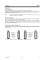
Símbolos y definiciones de seguridad
Ver manual
de
instrucciones
del uso
Informaciones
para
maquinaria
con uns peso
de > 18kg
potencia EN
MARCHA/PARADA
1171.0000.42-02.00
Peligro de
golpe de
corriente
Indicación
Stand-by
¡Advertencia!
Superficie
caliente
Corriente
continua
DC
Conexión a
conductor
protector
Corriente
alterna AC
Conexión
a tierra
Corriente
continua/alterna
DC/AC
Conexión
a masa
conductora
¡Cuidado!
Elementos de
construción
con peligro de
carga
electroestática
El aparato está
protegido en su
totalidad por un
aislamiento de
doble refuerzo
página 1
Informaciones de seguridad
Tener en cuenta las informaciones de seguridad sirve para tratar de evitar daños y peligros de toda
clase. Es necesario de que se lean las siguientes informaciones de seguridad concienzudamente y se
tengan en cuenta debidamente antes de la puesta en funcionamiento del producto. También deberán
ser tenidas en cuenta las informaciones para la protección de personas que encontrarán en otro
capítulo de esta documentación y que también son obligatorias de seguir. En las informaciones de
seguridad actuales hemos juntado todos los objetos vendidos por Rohde&Schwarz bajo la
denominación de „producto“, entre ellos también aparatos, instalaciones así como toda clase de
accesorios.
Palabras de señal y su significado
PELIGRO
Indica un punto de peligro con gran potencial de riesgo para el
ususario.Punto de peligro que puede llevar hasta la muerte o graves
heridas.
ADVERTENCIA
Indica un punto de peligro con un protencial de riesgo mediano para el
usuario. Punto de peligro que puede llevar hasta la muerte o graves
heridas .
ATENCIÓN
Indica un punto de peligro con un protencial de riesgo pequeño para el
usuario. Punto de peligro que puede llevar hasta heridas leves o
pequeñas
CUIDADO
Indica la posibilidad de utilizar mal el producto y a consecuencia
dañarlo.
INFORMACIÓN
Indica una situación en la que deberían seguirse las instrucciones en el
uso del producto, pero que no consecuentemente deben de llevar a un
daño del mismo.
Las palabras de señal corresponden a la definición habitual para aplicaciones civiles en el ámbito de la
comunidad económica europea. Pueden existir definiciones diferentes a esta definición. Por eso se
debera tener en cuenta que las palabras de señal aquí descritas sean utilizadas siempre solamente en
combinación con la correspondiente documentación y solamente en combinación con el producto
correspondiente. La utilización de las palabras de señal en combinación con productos o
documentaciones que no les correspondan puede llevar a malinterpretaciones y tener por
consecuencia daños en personas u objetos.
Informaciones de seguridad elementales
1. El producto solamente debe ser utilizado
según lo indicado por el fabricante referente
a la situación y posición de funcionamiento
sin que se obstruya la ventilación. Si no se
convino de otra manera, es para los
productos R&S válido lo que sigue:
como posición de funcionamiento se define
principialmente la posición con el suelo de la
caja para abajo , modo de protección IP 2X,
grado de suciedad 2, categoría de
sobrecarga eléctrica 2, utilizar solamente en
estancias interiores, utilización hasta 2000 m
sobre el nivel del mar.
A menos que se especifique otra cosa en la
hoja de datos, se aplicará una tolerancia de
±10% sobre el voltaje nominal y de ±5%
sobre la frecuencia nominal.
1171.0000.42-02.00
2. En todos los trabajos deberán ser tenidas en
cuenta las normas locales de seguridad de
trabajo y de prevención de accidentes. El
producto solamente debe de ser abierto por
personal périto autorizado. Antes de efectuar
trabajos en el producto o abrirlo deberá este
ser desconectado de la corriente. El ajuste,
el cambio de partes, la manutención y la
reparación deberán ser solamente
efectuadas por electricistas autorizados por
R&S. Si se reponen partes con importancia
para los aspectos de seguridad (por ejemplo
el enchufe, los transformadores o los
fusibles), solamente podrán ser sustituidos
por partes originales. Despues de cada
recambio de partes elementales para la
seguridad deberá ser efectuado un control de
página 2
Informaciones de seguridad
seguridad (control a primera vista, control de
conductor protector, medición de resistencia
de aislamiento, medición de medición de la
corriente
conductora,
control
de
funcionamiento).
3. Como en todo producto de fabricación
industrial no puede ser excluido en general
de que se produzcan al usarlo elementos
que puedan generar alergias, los llamados
elementos alergénicos (por ejemplo el
níquel). Si se producieran en el trato con
productos R&S reacciones alérgicas, como
por ejemplo urticaria, estornudos frecuentes,
irritación de la conjuntiva o dificultades al
respirar, se deberá consultar inmediatamente
a un médico para averigurar los motivos de
estas reacciones.
4. Si productos / elementos de construcción son
tratados fuera del funcionamiento definido de
forma mecánica o térmica, pueden generarse
elementos peligrosos (polvos de sustancia
de metales pesados como por ejemplo
plomo, berilio, níquel). La partición elemental
del producto, como por ejemplo sucede en el
tratamiento de materias residuales, debe de
ser efectuada solamente por personal
especializado para estos tratamientos. La
partición elemental efectuada
inadecuadamente puede generar daños para
la salud. Se deben tener en cuenta las
directivas nacionales referentes al
tratamiento de materias residuales.
5. En el caso de que se produjeran agentes de
peligro o combustibles en la aplicación del
producto que debieran de ser transferidos a
un tratamiento de materias residuales, como
por ejemplo agentes refrigerantes que deben
ser repuestos en periodos definidos, o
aceites para motores, deberan ser tenidas en
cuenta las prescripciones de seguridad del
fabricante de estos agentes de peligro o
combustibles y las regulaciones regionales
para el tratamiento de materias residuales.
Cuiden también de tener en cuenta en caso
dado las prescripciones de seguridad
especiales en la descripción del producto.
6. Ciertos productos, como por ejemplo las
instalaciones de radiación HF, pueden a
causa de su función natural, emitir una
radiación electromagnética aumentada. En
vista a la protección de la vida en desarrollo
deberían ser protegidas personas
embarazadas debidamente. También las
personas con un bypass pueden correr
1171.0000.42-02.00
peligro a causa de la radiación
electromagnética. El empresario está
comprometido a valorar y señalar areas de
trabajo en las que se corra un riesgo de
exposición a radiaciones aumentadas de
riesgo aumentado para evitar riesgos.
7. La utilización de los productos requiere
instrucciones especiales y una alta
concentración en el manejo. Debe de
ponerse por seguro de que las personas que
manejen los productos estén a la altura de
los requerimientos necesarios referente a
sus aptitudes físicas, psíquicas y
emocionales, ya que de otra manera no se
pueden excluir lesiones o daños de objetos.
El empresario lleva la responsabilidad de
seleccionar el personal usuario apto para el
manejo de los productos.
8. Antes de la puesta en marcha del producto
se deberá tener por seguro de que la tensión
preseleccionada en el producto equivalga a
la del la red de distribución. Si es necesario
cambiar la preselección de la tensión
también se deberán en caso dabo cambiar
los fusibles correspondientes del prodcuto.
9. Productos de la clase de seguridad I con
alimentación móvil y enchufe individual de
producto solamente deberán ser conectados
para el funcionamiento a tomas de corriente
de contacto de seguridad y con conductor
protector conectado.
10. Queda prohibida toda clase de interrupción
intencionada del conductor protector, tanto
en la toma de corriente como en el mismo
producto ya que puede tener como
consecuencia el peligro de golpe de corriente
por el producto. Si se utilizaran cables o
enchufes de extensión se deberá poner al
seguro, que es controlado su estado técnico
de seguridad.
11. Si el producto no está equipado con un
interruptor para desconectarlo de la red, se
deberá considerar el enchufe del cable de
distribución como interruptor. En estos casos
deberá asegurar de que el enchufe sea de
fácil acceso y nabejo (medida del cable de
distribución aproximadamente 2 m). Los
interruptores de función o electrónicos no
son aptos para el corte de la red eléctrica. Si
los productos sin interruptor están integrados
en construciones o instalaciones, se deberá
instalar el interruptor al nivel de la
instalación.
página 3
Informaciones de seguridad
12. No utilice nunca el producto si está dañado el
cable eléctrico. Asegure a través de las
medidas de protección y de instalación
adecuadas de que el cable de eléctrico no
pueda ser dañado o de que nadie pueda ser
dañado por él, por ejemplo al tropezar o por
un golpe de corriente.
20. En caso de que los productos que son
instalados fijamente en un lugar sean sin
protector implementado, autointerruptor o
similares objetos de protección, deberá la
toma de corriente estar protegida de manera
que los productos o los usuarios estén
suficientemente protegidos.
13. Solamente está permitido el funcionamiento
en redes de distribución TN/TT aseguradas
con fusibles de como máximo 16 A.
21. Por favor, no introduzca ningún objeto que
no esté destinado a ello en los orificios de la
caja del aparato. No vierta nunca ninguna
clase de líquidos sobre o en la caja. Esto
puede producir corto circuitos en el producto
y/o puede causar golpes de corriente, fuego
o heridas.
14. Nunca conecte el enchufe en tomas de
corriente sucias o llenas de polvo. Introduzca
el enchufe por completo y fuertemente en la
toma de corriente. Si no tiene en
consideración estas indicaciones se arriesga
a que se originen chispas, fuego y/o heridas.
15. No sobrecargue las tomas de corriente, los
cables de extensión o los enchufes de
extensión ya que esto pudiera causar fuego
o golpes de corriente.
16. En las mediciones en circuitos de corriente
con una tensión de entrada de Ueff > 30 V se
deberá tomar las precauciones debidas para
impedir cualquier peligro (por ejemplo
medios de medición adecuados, seguros,
limitación de tensión, corte protector,
aislamiento etc.).
17. En caso de conexión con aparatos de la
técnica informática se deberá tener en
cuenta que estos cumplan los requisitos de
la EC950/EN60950.
18. Nunca abra la tapa o parte de ella si el
producto está en funcionamiento. Esto pone
a descubierto los cables y componentes
eléctricos y puede causar heridas, fuego o
daños en el producto.
19. Si un producto es instalado fijamente en un
lugar, se deberá primero conectar el
conductor protector fijo con el conductor
protector del aparato antes de hacer
cualquier otra conexión. La instalación y la
conexión deberán ser efecutadas por un
electricista especializado.
1171.0000.42-02.00
22. Asegúrese con la protección adecuada de
que no pueda originarse en el producto una
sobrecarga por ejemplo a causa de una
tormenta. Si no se verá el personal que lo
utilice expuesto al peligro de un golpe de
corriente.
23. Los productos R&S no están protegidos
contra el agua si no es que exista otra
indicación, ver también punto 1. Si no se
tiene en cuenta esto se arriesga el peligro de
golpe de corriente o de daños en el producto
lo cual también puede llevar al peligro de
personas.
24. No utilice el producto bajo condiciones en las
que pueda producirse y se hayan producido
líquidos de condensación en o dentro del
producto como por ejemplo cuando se
desplaza el producto de un lugar frío a un
lugar caliente.
25. Por favor no cierre ninguna ranura u orificio
del producto, ya que estas son necesarias
para la ventilación e impiden que el producto
se caliente demasiado. No pongan el
producto encima de materiales blandos como
por ejemplo sofás o alfombras o dentro de
una caja cerrada, si esta no está
suficientemente ventilada.
26. No ponga el producto sobre aparatos que
produzcan calor, como por ejemplo
radiadores o calentadores. La temperatura
ambiental no debe superar la temperatura
máxima especificada en la hoja de datos.
página 4
Informaciones de seguridad
27. Baterías y acumuladores no deben de ser
expuestos a temperaturas altas o al fuego.
Guardar baterías y acumuladores fuera del
alcance de los niños. Si las baterías o los
acumuladores no son cambiados con la
debida atención existirá peligro de explosión
(atención celulas de Litio). Cambiar las
baterías o los acumuladores solamente por
los del tipo R&S correspondiente (ver lista de
piezas de recambio). Baterías y
acumuladores son deshechos problemáticos.
Por favor tirenlos en los recipientes
especiales para este fín. Por favor tengan en
cuenta las prescripciones nacionales de cada
país referente al tratamiento de deshechos.
Nunca sometan las baterías o acumuladores
a un corto circuito.
28. Tengan en consideración de que en caso de
un incendio pueden escaparse gases tóxicos
del producto, que pueden causar daños a la
salud.
29. Por favor tengan en cuenta que en caso de
un incendio pueden desprenderse del
producto agentes venenosos (gases, líquidos
etc.) que pueden generar daños a la salud.
30. No sitúe el producto encima de superficies,
vehículos, estantes o mesas, que por sus
características de peso o de estabilidad no
sean aptas para él. Siga siempre las
instrucciones de instalación del fabricante
cuando instale y asegure el producto en
objetos o estructuras (por ejemplo paredes y
estantes).
1171.0000.42-02.00
31. Las asas instaladas en los productos sirven
solamente de ayuda para el manejo que
solamente está previsto para personas. Por
eso no está permitido utilizar las asas para la
sujecion en o sobre medios de transporte
como por ejemplo grúas, carretillas
elevadoras de horquilla, carros etc. El
usuario es responsable de que los productos
sean sujetados de forma segura a los medios
de transporte y de que las prescripciones de
seguridad del fabricante de los medios de
transporte sean tenidas en cuenta. En caso
de que no se tengan en cuenta pueden
causarse daños en personas y objetos.
32. Si llega a utilizar el producto dentro de un
vehículo, queda en la responsabilidad
absoluta del conductor que conducir el
vehículo de manera segura. Asegure el
producto dentro del vehículo debidamente
para evitar en caso de un accidente las
lesiones u otra clase de daños. No utilice
nunca el producto dentro de un vehículo en
movimiento si esto pudiera distraer al
conductor. Siempre queda en la
responsabilidad absoluta del conductor la
seguridad del vehículo y el fabricante no
asumirá ninguna clase de responsabilidad
por accidentes o colisiones.
33. Dado el caso de que esté integrado un
producto de laser en un producto R&S (por
ejemplo CD/DVD-ROM) no utilice otras
instalaciones o funciones que las descritas
en la documentación. De otra manera pondrá
en peligro su salud, ya que el rayo laser
puede dañar irreversiblemente sus ojos.
Nunca trate de descomponer estos
productos. Nunca mire dentro del rayo laser.
página 5
EC Certificate of Conformity
Certificate No.: 99037
This is to certify that:
Equipment type
Order No.
Designation
ABFS
1114.8506.02
Baseband Fading Simulator
ABFS-B1
ABFS-B2
ABFS-B3
1115.0009.02
1115.0309.02
1115.0609.02
Option: Noise Generator
Option: Second Fading Simulator
Option: Second Noise Generator
complies with the provisions of the Directive of the Council of the European Union on the
approximation of the laws of the Member States
- relating to electrical equipment for use within defined voltage limits
(73/23/EEC revised by 93/68/EEC)
- relating to electromagnetic compatibility
(89/336/EEC revised by 91/263/EEC, 92/31/EEC, 93/68/EEC)
Conformity is proven by compliance with the following standards:
EN61010-1 : 1993 + A2 : 1995
EN50081-1 : 1992
EN50082-2 : 1995
Affixing the EC conformity mark as from 1999
ROHDE & SCHWARZ GmbH & Co. KG
Mühldorfstr. 15, D-81671 München
Munich, 1999-06-16
1114.8506.02
Central Quality Management FS-QZ / Becker
CE
E-1
ABFS
General Overview of Manuals
General Overview of Manuals
Operating Manual for Baseband Fading Simulator ABFS
This operating manual provides you with all the information necessary for putting into operation, manual
and remote control as well as repair of Baseband Fading Simulator ABFS and also contains specifications
of the instrument and available options.
The following options are described in this manual:
ABFS-B1 – Noise generator
ABFS-B2 – Second Fading simulator
ABFS-B3 – Second Noise generator
The contents of the chapters are as follows:
Data sheet
informs you about guaranteed specifications relating to functions and
characteristics of the instrument and its options.
Chapter 1
contains all information about putting into operation (unpacking, connection to
AC supply, switching on and off), functional testing and installation of the
instrument, preset settings and views of the front and rear panel showing the
controls and connectors needed for operation.
Chapter 2
presents a brief introduction and typical settings to users working with the
ABFS for the first time.
Chapter 3
describes manual control of the Baseband Fading Simulator, for example
calling up of menus, selection and editing of parameters, use of the list editor
and the SAVE/RECALL function. This chapter also contains an overview of
menus showing the functions available for the instruments and its options.
Chapter 4
describes the functions of the instrument and its options which can be
activated manually via menus or by remote control (fading, noise generation,
Memory Sequence, HOP CONTROL and general functions not directly related
to signal generation).
Chapter 5
provides basic information on remote control, for example on the IEC/IEEE
bus, RS-232-C interface, interface and device messages, command processing, status reporting system, etc.
Chapter 6
contains for each command system an overview and description of all commands available for the instrument and its options as well as an alphabetical list
of all commands.
Chapter 7
includes programming examples for remote control.
Chapter 8
gives information on preventive maintenance, for example for keeping the
exterior clean, storage, etc.
Chapter 9
contains the SCPI-specific and device-specific error messages displayed by
the instrument.
Chapter 10
includes the index.
Service Manual Instrument for Baseband Fading Simulator ABFS
The service manual instrument for Baseband Fading Simulator ABFS provides information on the
checking of rated characteristics, manual and electronic adjustment, repair (fault diagnosis, module
replacement), and the fitting of options. Moreover, it includes documentation such as spare parts list,
basic circuit diagram, block diagram, etc.
1114.8564.12
E
E-1
ABFS
1
Putting into Operation
Putting into Operation
This chapter contains all information about putting into operation (unpacking, connection to AC supply,
switching on and off), functional testing and installation of the instrument, preset settings and views of
the front and rear panel showing the controls and connectors needed for operation.
General Instructions
Before putting the ABFS into operation, please make sure that
•
•
•
•
the covers of the casing are put on and screwed,
the ventilation openings are free,
no signal voltage levels exceeding the permissible limits are applied at the inputs,
the outputs of the instrument are not overloaded or connected incorrectly.
If these points are not observed, the instrument might be damaged.
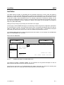
Unpacking the Instrument
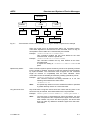
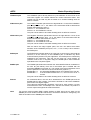
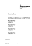
À Take the instrument out of the shipping box and check whether the
items listed in the packing list and in the lists of accessories are all
included.
remove protective cabs
À Remove the two protective caps from the front and rear of the
ABFS and carefully check the instrument for damage.
Should the instrument be damaged, immediately notify the forwarder who shipped the instrument to you
and keep the box and packing material.
For further transport or shipment of the ABFS the original packing should also be used. It is
recommended to keep at least the two protective caps for front and rear side in order to prevent
damage to the controls and connectors.
Supply Voltage
The ABFS can be operated at a.c. systems from 90 to 132 V and 180 to 265 V at system frequencies
from 47 to 440 Hz. The power supply socket is situated at the rear of the instrument. The instrument
automatically sets itself to the voltage applied within the permissible voltage ranges. It is not necessary
to set the instrument to a certain supply voltage.
How to Ensure EMC
In order to avoid electromagnetic interference, the instrument may only be operated when it is closed
and with all shielding covers fitted. Only appropriate shielded signal and control cables may be used.
1114.8564.12
1.1
E-1
Putting into Operation
ABFS
Switching On/Off the Instrument
Power switch at the rear of the instrument
Switch on/off:
Power switch
Power supply socket
À Press power switch at the top (I) / bottom (0)
The power switch can remain switched on permanently.
Switching off is only necessary when the instrument is to be
completely disconnected from the mains.
On/Off switch at the front of the instrument
Standby check LED
À Press switch.
The instrument is ready for operation.
À Release switch.
The instrument assumes the STANDBY mode.
Switch on:
Switch off:
Initial Status
Upon switching on, the instrument automatically assumes the status which was set when it was
switched off.
If the instrument need not to be operated from the initial status any further, a defined default status
should be established by pressing the [PRESET] key prior to further settings.
Setting Contrast and Brightness of the Display
Brightness control
Contrast control
Contrast and brightness of the display can be set by means of the contrast and brightness controls
situated below the display.
RAM With Battery Back-Up
The ABFS has a static read-write memory (CMOS-RAM) with battery back-up, in which 50 different
complete settings of the instrument can be stored (cf. Chapter 3, section "Storing and Calling of
Instrument Settings"). In addition, all data and/or lists the user enters himself, such as for list mode or
memory sequence, are stored in the RAM. Further, all data of the calibrations running within the
instrument in the ABFS are stored in the RAM (cf. Chapter 4, section "Calibration" and Service Manual Instrument).
A lithium battery with a service life of approx. 5 years serves to supply the RAM with power. When the
battery is discharged, the data stored will be lost. Exchanging the battery is described in the Service
Manual - Instrument.
1114.8564.12
1.2
E-1
ABFS
Putting into Operation
Preset Setting
A defined setting status is achieved by pressing the [PRESET] key.
Preset Status:
Mode
Fading
AWGN
Memory Sequence
Hop Control
Protection of calibration data
Settings stored
Data, lists etc. stored
IEC-bus address
Beeper
1channel / 12path
switched off
switched off
switched off
switched off
Protection lock: unaltered
unaltered
unaltered
unaltered
unaltered
All parameters and circuit states, even those of operating modes which are not activated, are preset by
means of Preset.
The presettings going beyond the above list can be seen from the menu representations as of Section 4
which each indicate the Preset setting status.
Functional Test
On switching on the instrument and permanently during operation, the ABFS carries out a self test. The
ROM contents as well as the battery of the non-volatile RAM are checked on switching on the
instrument and the RAM contents with every calling the memory. The most important instrument
functions are automatically monitored during operation.
If an error is detected, the message "ERROR" is displayed in the status line. For further identification of
the error, press the [ERROR] key. Thereupon a description of the error/s is displayed (cf. Chapter 9,
section "Error Messages"). Return to the menu exited by pressing the [BACK] key.
If required, the self tests can be induced purposefully. Further, internal test points can be polled by the
user and the results be read out and displayed. Cf. Service Manual Instrument.
Mounting into a 19" Rack
Caution:
Ensure free air inlet/outlet at the perforation of the side walls of the instrument in rack
mounting.
The ABFS can be mounted into a 19" rack by means of rack adapter ZZA-94 (stock no. 396.4905.00).
The mounting instructions are attached to the adapter.
1114.8564.12
1.3
E-1
Fig. 1-1
1114.8564.12
15.0
12.0
dB
dB
1.4
ASSIGN
7
MENU1
dBfs
dBfs
AWGN A/B
-18.0
-22.0
MENU2
QUICK SELECT
FSIM B-2CH/2IN/2OUT
NLEV B2
NLEV A1
15.0
12.0
dB
dB
6
VE RSI ON:
PRESET
1 .0
ERROR
Pre vious m enu
RE TUR N
Nex t menu
Move cur sor
OPERAT ING
ILOSS B2
ILOSS B1
SE LEC T
ABFS
5
STATUS
HELP
×
RETURN
RCL
SAVE
MODE
GRP B
MODE
GRP A
.
2
5
8
-
3
6
9
LOCAL
Ø
SELECT
FADING
0N/0FF
4
x1
m
µ
n
AWGN
0N/0FF
ENTER
k
M
G
dB(m)
mV
µV
dBµV
1114.8506.02
MENU / VARIATION
0
1
4
7
DATA INPUT
2
Ï
8
MODE
GROUPA FSIM
AWGN
GROUPB FSIM
AWGN
CALIBRATE
MEM SEQ
HOP CONTROL
UTILITIES
HELP
FSIM A-2CH/2IN/2OUT
ILOSS A2
ILOSS A1
FADING SIMULATOR
1
3
MA DE IN GERMANY
Front Panel
ABFS
Front panel view ABFS
E-1
ABFS
Front Panel
Explanation of Front and Rear Panel
Elements of the Front Panel
1
Display
Cf. Chapter 3, section "Design of the Display".
2
DATA INPUT
Parameter field
As an alternative to menu control, the parameter keys
can be used to switch over ABFS operating modes
and signal paths. A graphic with the associated signal
paths is displayed in the menu. Complete device
settings may also be stored and called up.
MODE
GRP A
MODE
GRP B
SAVE
See as well
Chapter 3,
MODE GRP A
RCL
MODE GRP B
Toggle key to change the operating mode of
GROUP A or GROUP B of ABFS. After
pressing the key, a window is opened in
which the set signal paths are displayed in a
graphic. The window is independent of the
current menu control and menu hierarchy.
The graphic is identical with that in the
MODE menu.
SAVE
RCL
Opens the storing of the current instrument
setting. Memory selection is effected by
entering a number (1 to 50) and is finished by
means of the [ENTER] key.
Section
"Use of [MODE GRP A]
and [MODE GRP B]"
Section
"Storing and Calling of
Instrument Settings"
Opens the calling of an instrument setting
stored. Memory selection is effected by
entering a number (1 to 50) and is finished by
means of the [ENTER] key.
Numeric input field
7
8
9
Numeric values, decimal point and minus sign can be
entered by means of the digital keys.,
See as well
Chapter 3,
4
5
6
0...9
Enters the digit.
1
2
3
ì
Enters the decimal point
Section
"Basic Operating
Steps"
0
.
Ï
-/←
Enters the minus sign.
-
1114.8564.12
Deletes the last input (digit, sign or decimal
point) - key [BACKSPACE].
1.5
E-1
Fig. 1-1
1114.8564.12
15.0
12.0
dB
dB
1.6
ASSIGN
7
MENU1
dBfs
dBfs
AWGN A/B
-18.0
-22.0
MENU2
QUICK SELECT
FSIM B-2CH/2IN/2OUT
NLEV B2
NLEV A1
15.0
12.0
dB
dB
6
VE RSI ON:
PRESET
1 .0
ERROR
Pre vious m enu
RE TUR N
Nex t menu
Move cur sor
OPERAT ING
ILOSS B2
ILOSS B1
SE LEC T
ABFS
5
STATUS
HELP
×
RETURN
RCL
SAVE
MODE
GRP B
MODE
GRP A
.
2
5
8
-
3
6
9
LOCAL
Ø
SELECT
FADING
0N/0FF
4
x1
m
µ
n
AWGN
0N/0FF
ENTER
k
M
G
dB(m)
mV
µV
dBµV
1114.8506.02
MENU / VARIATION
0
1
4
7
DATA INPUT
2
Ï
8
MODE
GROUPA FSIM
AWGN
GROUPB FSIM
AWGN
CALIBRATE
MEM SEQ
HOP CONTROL
UTILITIES
HELP
FSIM A-2CH/2IN/2OUT
ILOSS A2
ILOSS A1
FADING SIMULATOR
1
3
MA DE IN GERMANY
Front Panel
ABFS
Front panel view ABFS
E-1
ABFS
2
Front Panel
DATA INPUT
Unit keys with enter function
G
n dBµV
M
µ
µV
m
mV
The unit keys terminate the input of values and specify
the multiplication factor for the respective basic unit.
The basic units are displayed next to the input field
while numbers are entered. In the case of level
settings, the unit keys specify the unit.
k
G/n
dBµV
Selects giga/nano, with RF level
dBµV, with LF level dBu.
M/µ
µV
Selects mega/micro, with level µV.
k/m
MV
Selects kilo/milli, with level mV.
x1
ENTER
dB(m)
1x
Enter
See as well
Chapter 3,
Section
"Basic Operating Steps"
Section
"Change Unit of Level"
dB(m) Terminates entries in the basic
unit and value inputs without unit.
Selects with level dBm
Selects with level offset and level
step width dB.
In order to change to another level unit, simply press
the unit key desired. Parameter LEVEL must be
activated, e.g. by pressing the [LEVEL] key.
3
MENU/VARIATION
Menu keys
RETURN
×
SELECT
Ø
1114.8564.12
The menu keys access the menus and settings within
the menus.
RETURN
Returns the menu cursor to the next
higher menu level.
SELECT
Acknowledges the choice marked
by the menu cursor
⇐
Moves the digit cursor to the left by
one position in the marked value
indication.
Moves the menu cursor to the left
by one position in a 1-out-of-n
selection.
⇒
Moves the digit cursor to the right
by one position in the marked value
indication.
Moves the menu cursor to the right
by one position in a 1-out-of-n
selection.
1.7
see as well
Chapter 3
Section
"Basic Operating Steps"
E-1
Fig. 1-1
1114.8564.12
15.0
12.0
dB
dB
1.8
ASSIGN
7
MENU1
dBfs
dBfs
AWGN A/B
-18.0
-22.0
MENU2
QUICK SELECT
FSIM B-2CH/2IN/2OUT
NLEV B2
NLEV A1
15.0
12.0
dB
dB
6
VE RSI ON:
PRESET
1 .0
ERROR
Pre vious m enu
RE TUR N
Nex t menu
Move cur sor
OPERAT ING
ILOSS B2
ILOSS B1
SE LEC T
ABFS
5
STATUS
HELP
×
RETURN
RCL
SAVE
MODE
GRP B
MODE
GRP A
.
2
5
8
-
3
6
9
LOCAL
Ø
SELECT
FADING
0N/0FF
4
x1
m
µ
n
AWGN
0N/0FF
ENTER
k
M
G
dB(m)
mV
µV
dBµV
1114.8506.02
MENU / VARIATION
0
1
4
7
DATA INPUT
2
Ï
8
MODE
GROUPA FSIM
AWGN
GROUPB FSIM
AWGN
CALIBRATE
MEM SEQ
HOP CONTROL
UTILITIES
HELP
FSIM A-2CH/2IN/2OUT
ILOSS A2
ILOSS A1
FADING SIMULATOR
1
3
MA DE IN GERMANY
Front Panel
ABFS
Front panel view ABFS
E-1
ABFS
3
Front Panel
MENU/VARIATION
Rotary knob
The rotary knob moves the menu cursor over the
positions of a menu level to choose from or varies the
value of a parameter. The variation is either effected in
steps of one or in a step width that can be specified at
will.
See as well Chapter 3
FADING
ON/OFF
See as well
Chapter 3,
Section "Use of
[FADING ON/OFF] and
[AWGN ON/OFF] Keys"
Section
"Basic Operating Steps"
Chapter 2, Section
"Sample Setting for
First Users"
4
FADING
0N/0FF
AWGN
0N/0FF
Switches all the fading simulators
on or off.
AWGN
ON/OFF
Switches all the noise generators
on or off.
5
PRESET
ERROR
STATUS
HELP
LOCAL
PRESET
Establishes a defined instrument
status.
See as well Chapter 1,
Section "Preset Settings"
ERROR*
Indicates error and caution
messages.
Chapter 9, Section
"Error Messages"
STATUS*
Indicates the instrument status.
HELP*
Indicates context-sensitive auxiliary
text.
Chapter 4,
Section "Status"
LOCAL
Switches the instrument from the
REMOTE mode (remote control) to
the LOCAL mode (manual control).
Section
"The Help System"
Section
"Remote Control"
* Exit the menus using the [RETURN] key.
1114.8564.12
1.9
E-1
Fig. 1-1
1114.8564.12
15.0
12.0
dB
dB
1.10
ASSIGN
7
MENU1
dBfs
dBfs
AWGN A/B
-18.0
-22.0
MENU2
QUICK SELECT
FSIM B-2CH/2IN/2OUT
NLEV B2
NLEV A1
15.0
12.0
dB
dB
6
VE RSI ON:
PRESET
1 .0
ERROR
Pre vious m enu
RE TUR N
Nex t menu
Move cur sor
OPERAT ING
ILOSS B2
ILOSS B1
SE LEC T
ABFS
5
STATUS
HELP
×
RETURN
RCL
SAVE
MODE
GRP B
MODE
GRP A
.
2
5
8
-
3
6
9
LOCAL
Ø
SELECT
FADING
0N/0FF
4
x1
m
µ
n
AWGN
0N/0FF
ENTER
k
M
G
dB(m)
mV
µV
dBµV
1114.8506.02
MENU / VARIATION
0
1
4
7
DATA INPUT
2
Ï
8
MODE
GROUPA FSIM
AWGN
GROUPB FSIM
AWGN
CALIBRATE
MEM SEQ
HOP CONTROL
UTILITIES
HELP
FSIM A-2CH/2IN/2OUT
ILOSS A2
ILOSS A1
FADING SIMULATOR
1
3
MA DE IN GERMANY
Front Panel
ABFS
Front panel view ABFS
E-1
ABFS
6
Front Panel
BRIGHTNESS / CONTRAST
Brightness and contrast of the display can be set using
the rotary knobs.
Contrast
Brightness
7
See as well Chapter 1,
Section
"Setting of Contrast
and Brightness of the
Display"
QUICK SELECT
QUICK SELECT
ASSIGN
8
MENU1
MENU2
The menu-quick-selection keys permit fast access to
two menus selected.
See as well
Chapter 3,
ASSIGN
Stores the current menu as menu1
when the MENU1 key is pressed
afterwards or as menu2 when the
MENU2 key is pressed afterwards.
Section "Basic
Operating Steps"
MENU1
Activates menu1 stored.
MENU2
Activates menu2 stored.
ON/OFF SWITCH
The On/Off switch switches the instrument from the
standby mode to the ready-for-operation status.
Prerequisite: The power switch at the rear of the
instrument must be switched on.
The LED is illuminated in the standby mode.
1114.8564.12
1.11
See as well Chapter 1,
Section "Switching
On/Off the Instrument"
Section "Elements of
the Rear Panel, Power
Switch"
E-1
Fig. 1-2
1114.8564.12
I
I
I
I
IN 2
IN 1
IN 2
IN 1
I
I
Q
Q
I
I
GROUP B
Q
Q
G ROUP A
1
OUT 2
OUT 1
OUT 2
OUT 1
Q
Q
Q
Q
625
1.12
7
IEEE 488
RS 232
HOP CONTROL 2
HOP CONTROL 1
BLANK OUT
TRIGG ER
IN 1
IN 2
2
3
6
5
4
Rear Panel
ABFS
Rear panel view ABFS
E-1
ABFS
Rear Panel
Elements of the Rear Panel
1
GROUP A / GROUP B
GROUP A
GROUP A
I
I
IN 1
OUT 1
Q
I
Q
I
IN 2
Q
OUT 2
Q
GROUP B
I
I
2
IN 1
Q
I
Q
I
OUT 1
IN 2
Q
OUT 2
Q
TRIGGER
TRIGGER
IN 1
IN 2
TRIGGER
IN 1
IN 2
3
Trigger Input
HOP CONTROL 1.
Level: TTL
See as well
Chapter 4,
Section
"HOP CONTROL“
Trigger Input
HOP CONTROL 2.
Level: TTL
BLANK OUT
BLANK OUT
4
GROUP B Baseband inputs and
outputs. The active inputs
and outputs are displayed, depending on the
selected operating mode
and the options installed,
in submenu MODE.
Input/output resistance:
50 Ω.
Nominal voltage:
Us = 0.5 V
Max. permissible
overvoltage: ± 5 V
BLANK OUT
Output to blank out the frequency
change of fading generators during
HOP CONTROL.
Level: TTL
POWER SWITCH
Power switch
ON when pressed at the top ("I")
See as well Chapter 1,
Section "Supply voltage"
Section "Switching
On/Off the Instrument"
Power supply connector
1114.8564.12
1.13
E-1
Fig. 1-2
1114.8564.12
I
I
I
I
IN 2
IN 1
IN 2
IN 1
I
I
Q
Q
I
I
GROUP B
Q
Q
GROUP A
1
OUT 2
OUT 1
OUT 2
OUT 1
Q
Q
Q
Q
625
1.14
7
IEEE 488
RS 232
HOP CONTROL 2
HOP CONTROL 1
BLANK OUT
TRIGGER
IN 1
IN 2
2
3
6
5
4
Rear Panel
ABFS
Rear panel view ABFS
E-1
ABFS
5
Rear Panel
HOP CONTROL 1 / HOP CONTROL 2
HOP CONTROL 1
HOP CONTROL1
HOP CONTROL 2 RS-232 HOP CONTROL interfaces.
Transmission of a list index for
selection of a HOP frequency for
HOP CONTROL 1 or 2.
In addition to trigger inputs
TRIGGER IN 1 / IN 2 a trigger can
also be activated as an option via
the DSR line (pin 6).
HOP CONTROL2
6
Section
"HOP CONTROL“
RS 232
RS 232
RS 232
7
See as well
Chapter 4,
RS-232-C interface,
used for software update and remote
control. The pin assignment corresponds to the pin assignment of a PC.
IEC / IEEE488
625
IEEE 488
IEC 625/
IEEE 488
1114.8564.12
IEC/IEEE bus (IEEE 488)
Remote-control interface
1.15
See as well
Chapter 5,
Section "Interfaces"
E-1
ABFS
2
Connection of ABFS
Brief Introduction
This chapter provides information on the connection of ABFS and gives a short introduction with sample
settings for first-time users. It thus allows a fast familiarization with the operation of the unit.
Connection of ABFS
ABFS is a fading simulator that utilizes the complex baseband signals I and Q. It does not comprise any
signal source. It is located between the IQ source and RF upconverter in the baseband signal path (see
Fig. 2-1).
AMIQ
I/Q MODULAT ION GEN ERA TOR . AMIQ
ON
CONTROL
1110.2003. 02
I
RUNNING
Q
M ADE IN G ERM ANY
I
ABFS
Q
× Ø
RF Upconverter
cos(ωt)
RF OUT
I
Q
- sin(ωt)
Fig. 2-1
RF-Frequency
Connection of Fading Simulator ABFS
AMIQ from Rohde & Schwarz is for use as an external source to generate modulation signals required
for I/Q modulation. The generated signals are provided at the modulation outputs I and Q of AMIQ (front
panel).
It is also possible to connect an IQ modulation source to ABFS other than AMIQ. The maximum rated
input voltages must however be observed (see chapter 1, "Elements of the Rear Panel").
1114.8564.12
2.1
E-1
Sample Settings for First-Time Users
ABFS
Sample Settings for First-Time Users
Fading a GSM signal
"GSM TYPICAL URBAN 12 Path“ fading standard, RF carrier frequency = 904.5 MHz
First, the signal source (INPUT) and the upconverter (OUTPUT) are connected to ABFS. GROUP B
connectors are available only if option ABFS-B2 (second fading group) has been fitted.
GROUP A
I
I
I
IN 1
IN 2
OUT 1
Q
I
Q
I
Q
OUT 2
Q
Q
OUTPUT
INPUT
Q
I
I
Fig. 2-2
I
GROUP B
IN 1
Q
I
Q
I
IN 2
OUT 1
Q
OUT 2
Q
Signal input/outputs on rear panel of ABFS
The fading mode can be set via the [MODE GRP A] toggle key. Press the [MODE GRP A] key until the
1CHANNEL 12 PATH mode is displayed for GROUP A, see Fig. 2-3).
Operating steps
Explanations
Reset unit to defined state.
PRESET
Press key n-times until the FSIM A1CH/1IN/1OUT fading mode is
displayed in the status line.
MODE
GRP A
1114.8564.12
2.2
E-1
ABFS
Sample Settings for First-Time Users
ILOSS A1
0.0 dB
ILOSS A2
0.0 dB
FSIM A-1CH/1IN/1OUT
MODE
FSIM
CALIBRATE
MEM SEQ
HOP CONTROL
UTILITIES
HELP
GROUP A
IQ_IN1
IQ_OUT1
FSIMA1
FSIMA2
Fig. 2-3
Display for setting the fading mode
Setting the fading parameters
Operating steps
MENU / VARIATION
Explanations
MENU / VARIATION
.
Select FSIM menu using the rollkey
and press the SELECT key.
The submenu is displayed.
SELECT
FSIM
.
MENU / VARIATION
MENU / VARIATION
.
SELECT
STANDARD
Select STANDARD submenu and
press the SELECT key.
A selection of different fading
standards is displayed.
.
MENU / VARIATION
MENU / VARIATION
.
GSM TYPICAL URBAN 3
SELECT
.
1114.8564.12
2.3
Select GSM TYPICAL URBAN 3
standard using the rollkey and press
the SELECT key.
The display returns to the FSIM
menu and the parameters for the
standard are set.
E-1
Sample Settings for First-Time Users
ABFS
Operating steps
MENU / VARIATION
Explanations
MENU / VARIATION
Select RF-FREQUENCY using the
rollkey and press the SELECT key.
.
SELECT
RF FREQUENCY
.
Enter an RF carrier frequency of
904.5 MHz. The cursor returns to the
FSIM menu.
DATA INPUT
9
0
4
5
.
MENU / VARIATION
M
µ
µV
MENU / VARIATION
.
SELECT
STATE
Select STATE using the rollkey and
press the SELECT key.
The menu cursor marks the current
1-out-of-N selection.
.
MENU / VARIATION
MENU / VARIATION
.
RUN
SELECT
RETURN
.
1114.8564.12
2.4
Select RUN using the rollkey and
press the SELECT key. The cursor
jumps to RUN.
Press the RETURN key to again
return to the FSIM menu.
E-1
ABFS
Sample Settings for First-Time Users
ILOSS A1
12.4 dB
0.0 dB
ILOSS A2
FSIM A-1CH/1IN/1OUT
MODE
FSIM
CALIBRATE
MEM SEQ
HOP CONTROL
UTILITIES
HELP
STATE
RESET
STANDARD...
SPEED UNIT
SHOW PATH
INSERTION LOSS SETTING MODE
OFF
STOP
m/s
km/h mph
1..6 7..12
AUTO
MAN
COUPLED PARAMETERS...
SET DEFAULT
RF FREQUENCY
Fig. 2-4
RUN
904.500 000 0 MHz
CHANNEL1/PATH
STATE
PROFILE
DISCRETE COMP
1
ON
RAYL
OFF
2
ON
RAYL
OFF
3
ON
RAYL
OFF
4
ON
RAYL
OFF
5
ON
RAYL
OFF
6
ON
RAYL
OFF
SPEED
DOPPLER FREQ
PATH LOSS
DELAY
CORR PATH
COEFF
PHASE
LOGNORM STATE
LOCAL CONST
STD DEV
3.0
2.5
4.0
0.00
NONE
1.00
0
OFF
200
0
3.0
2.5
3.0
0.10
NONE
1.00
0
OFF
200
0
3.0
2.5
0.0
0.30
NONE
1.00
0
OFF
200
0
3.0
2.5
2.6
0.50
NONE
1.00
0
OFF
200
0
3.0
2.5
3.0
0.80
NONE
1.00
0
OFF
200
0
3.0 kmh
2.5 Hz
5.0 dB
1.10 us
NONE
1.00 %
0 deg
OFF
200 m
0 dB
Display for setting fading
1114.8564.12
2.5
E-1
ABFS
3
Design of the Display
Manual Operation
This chapter shows the design of the display and describes the manual control of the Baseband Fading
Simulator, for example calling up of menus, selection and editing of parameters, use of the list editor
and the SAVE/RECALL function. This chapter also contains an overview of menus showing the
functions available for the instruments and its options.
It is useful to read the sample settings for first users in Chapter 2, "Short Tutorial".
Design of the Display
1
ILOSS A1
15.0 dB
NLEV A1
2
FSIM A-2CH/2IN/2OUT
3
MODE
MODE FSIM
FSIM
AWGN
CALIBRATE
MEM SEQ
HOP CON TROL
UTILITIES
HELP
-21.0 dBfs
Main menu
Fig. 3-1
15.0 dB
AWGN A1
1CHANNEL/12PATH/1INPUT/1OUTPUT
2CHANNEL/ 6PATH/1INPUT/2OUTPUT
2CHANNEL/ 6PATH/2INPUT/1OUTPUT
2CHANNEL/ 6PATH/2INPUT/2OUTPUT
GROU
IQ_IN1
FSIMA1
IQ_IN2
1 Header
2 Status line
3 Menu fields
ILOSS A2
FSIMA2
Setting menu
Submenu
Menu cursor
Digit cursor
Select mark
Design of the display
(1) Header
Depending on the operating mode set, the header indicates the different insertion
losses for the individual channels (ILOSS = Insertion Loss). With options
ABFS-B1/ABFS-B3 fitted, it also indicates the set noise level (NLEV = Noise Level).
(2) Status line
The status line below describes operating mode and operating state of the instrument.
Error messages and notes for caution are also displayed in the status line.
(3) Menu fields
The indication fields below the header field are reserved for the menu representations.
The image contents of these fields change as a function of the menu selected. The
field at the left-hand display margin is occupied with the main menu, the topmost level
of the menu structure. The main menu is always faded in. Each further field adjacent
at the right contains submenus.
The field ending with the right-hand display margin shows the setting menu. In this
menu all setting values and setting states connected with the menu selected are
indicated. When accessing submenus, the higher-order menus remain in the display.
The current menu path is evident through the select marks.
Menu cursor
The menu cursor shows the user at which position in the menu he is.
The position of the menu cursor is evident from the inverse notation
of the term (white characters on a black background).
Digit cursor
As an underscore, the digit cursor marks the position which can be
varied by means of the rotary knob in a value indication.
Select mark
The frame around a term marks current menus or valid settings in the
setting menu.
1114.8564.12
3.1
E-1
Basic Operating Steps
ABFS
Basic Operating Steps
To operate the instrument, menus are called in the display. All setting possibilities and the current
setting status are evident from the menus. All settings can be made by accessing the menus.
Besides the menus, the keys [MODE GRP A] and [MODE GRP B] may also be used for making
settings on the signal paths of GROUP A/B. Likewise, the fading simulators and the noise generators
can be switched on and off not only via the menus but also by means of the keys [FADING ON/OFF]
and [AWGN ON/OFF].
Calling the menus
Accessing the menus is effected using rotary knob [VARIATION], [SELECT] key and [RETURN] key.
Rotary knob
Rotary knob [VARIATION] moves the menu cursor over the positions of a menu
level to be selected.
If a scrollbar is visible at the left-hand margin of a menu, the menu is larger than the
screen window. If the menu cursor is moved to the margin of the screen window, the
covered lines become visible.
[SELECT] key
The [SELECT] key acknowledges the selection marked by means of the menu
cursor.
[RETURN] key
The [RETURN] key
- returns the menu cursor to the next higher menu level; the menu cursor is shifted
to the left into the preceding column of the menu structure,
- closes the display pages called using keys [STATUS], [HELP] and [ERROR]
again.
Settings are accessed in the setting menus ending with the right-hand display margin.
ILOSS A1
15.0 dB
FSIM A-2CH/2IN/2OUT
MODE
FSIM
AWGN
CALIBRATE
MEM SEQ
HOP CONTROL
UTILITIES
HELP
Fig. 3-2
NLEV A1
-21.0 dBfs
ILOSS A2
15.0 dB
AWGN A1
MODE
RESET
STANDARD...
SPEED UNIT
SHOW PATH
INSERTION LOSS SETTING MODE
INSERTION LOSS MANUAL
COUPLED PARAMETERS...
SET DEFAULT
RF FREQUENCY
CHANNEL1/PATH
1
2
OFF
RUN
STOP
m/s km/h mph
CHANNEL1
CHANNEL2
AUTO
MANUAL
15.0 dB
3
4
100.000 000 0 Mhz
5
6
Fading setting menu
1114.8564.12
3.2
E-1
ABFS
Basic Operating Steps
Selection and Change of Parameters
Select parameter
À Set the menu cursor to the name of the parameter desired using the rotary
knob, e.g. to INSERTION LOSS MANUAL in the FSIM setting menu, see
Fig. 3-2.
Change setting
value
À Via value input or by means of rotary knob.
Via value inputs
À Press the first digit of the new value or minus sign.
The old value is deleted, the entry is indicated in the marked field.
À Enter further digits.
À Terminate the input using a unit key or, in the case of inputs in the base unit
or in the case of inputs without unit, using the [1x/Enter] key.
The menu cursor wraps back to the appropriate parameter.
Using rotary knob
À Press [SELECT] key.
The menu cursor changes from the parameter selected in the left-hand
column of the setting menu to the setting value on the right, e.g. from
INSERTION LOSS MANUAL to 15.0 dB, see Fig. 3-2.
À Set the underscore to the position of the setting value to be varied using
keys [Ø] [×].
À Turn rotary knob.
The position underscored is varied in steps of 1.
1-out-of-n selection
À Select parameter.
À Press [SELECT] key.
The menu cursor changes from the parameter selected in the left-hand
column of the setting menu to the current selection on the right, e.g. from
SPEED UNIT to km/h, see Fig. 3-2.
À Set the menu cursor to the position desired within the 1-out-of-n selection
using the rotary knob or cursor keys [⇐] [⇒].
À Press [SELECT] key.
The setting is made. The selection mark which has marked the setting valid
up to now wraps to the new position.
À Press the [RETURN] key.
The menu cursor wraps back to the respective parameter.
Quick selection of a The quick selection of a parameter reduces the number of operating steps if
parameter
several parameters are set successively. The menu cursor can directly be set
further from line to line in the column of the setting values by pressing the
[SELECT] key.
The menu cursor wraps from the setting value of a parameter to the setting
value of the parameter in the next line.
The column of the setting values can be exited at each position by pressing
the [RETURN] key.
1114.8564.12
3.3
E-1
Basic Operating Steps
ABFS
Triggering Action
Lines in the setting menu which are marked with the " " symbol at the end of the line qualify an action
which can be carried out. Instruction SET DEFAULT sets the default values of the path parameters.
Triggering action
À Set the menu cursor to the respective instruction.
À Press the [SELECT] key.
The action is triggered.
While the action is carried out, the instruction remains framed by the
selection mark.
Quick Selection of Menu (QUICK SELECT)
The keys [ASSIGN], [MENU1] and [MENU2] of the QUICK SELECT control field are used to call
selected menus quickly by one keystroke.
Store menus
À Establish the desired operating status of the current menu.
À Press [ASSIGN] key.
À Press [MENU1] or [MENU2] key.
The current menu is stored as menu1 or menu2. That is to say, 2 menus
can be stored in total.
Call menus
À Press [MENU1] or [MENU2] key.
Menu1 or menu2 stored is displayed. Exactly the operating status which
was current at the point of time of storing is reconstructed.
Using Keys [MODE GRP A] and [MODE GRP B]
Besides the menus, the keys [MODE GRP A] and [MODE GRP B] may also be used for making
settings on the signal paths of GROUP A/B.
Key [MODE GRP A]/
Key [MODE GRP B]
À Press key [MODE GRP A] or [MODE GRP B].
The various operating modes or signal paths of the group are selected
successively.
After pressing the key, a window is opened in which the set ABFS signal
paths are displayed in a graphic. The window is independent of the current
menu control and menu hierarchy. The graphic is identical with that in the
MODE menu. The window is cleared automatically after 10 seconds. If a
key is pressed while the signal paths are being displayed, the window will
be cleared and operation via menus continues.
1114.8564.12
3.4
E-1
ABFS
Basic Operating Steps
Using Keys [FADING ON/OFF] and [AWGN ON/OFF]
FADING and NOISE (AWGN Additive White Gaussian Noise) can be switched on and off not only in the
menus but also by means of the keys [FADING ON / OFF] and [AWGN ON / OFF].
Key
[FADING ON/OFF]
À Press key [FADING ON/OFF].
Switching all fading simulators on or off. If fading is switched off, 0.0 dB will
be indicated in the ILOSS displays.
Key
[AWGN ON/OFF]
À Press key [AWGN ON/OFF].
Switching all noise generators on or off.
Correction of Input
Digits can be corrected by one of the following keys before the input is confirmed by the [Enter] key:
Ï
Key [-/ ]
The backspace key deletes the value entered digit by digit. When the last
digit is deleted, the previous value is displayed.
Key [RETURN]
Pressing the [RETURN] key deletes the entire entry and results in the
previous value being indicated again.
For a subsequent new input in the setting menu, the digit of the new value is
to be entered.
Key [MODE GRP A]/
Key [MODE GRP B]
1114.8564.12
If a selection is made by pressing the keys [MODE GRP A] or [MODE GRP B],
a second press of the same key will delete the whole entry made.
3.5
E-1
List Editor
ABFS
List Editor
The ABFS offers the facility of generating lists for automatic sequences of HOP mode and Memory
Sequence. The lists consist of elements (pairs of values) which are defined by an index and at least one
parameter per index. Each list is assigned a separate name and selected by means of this name. Access
to the lists is made in the associated menus. For example, sequences of instrument settings can be
accessed in the MEM SEQ menu. However, the lists are always generated and processed in the same
way and the procedures are hence explained in detail in this section by the example of the Memory
Sequence (Menu MEM SEQ).
Setting menus providing list processing are structured in two pages:
The first page, called OPERATION page in the following contains the general configuration parameters
for processing a list. Further, the general list functions such as selecting and deleting the list as well as
calling an editing mode are provided. The second page, the EDIT page, is automatically displayed
when calling an edit function and serves to enter and modify the parameters of the list.
The OPERATION page has a similar arrangement with all list editors. As an example, the OPERATION
page of the MEM SEQ menu is shown:
Menu selection:MEM SEQ
ILOSS A1
0.0 dB
ILOSS A2
0.0 dB
FSIM A-2CH/2IN/2OUT
MODE
FSIM
AWGN
CALIBRATE
MEM SEQ
HOP CONTROL
UTILITIES
HELP
MODE
OFF
AUTO
SINGLE
EXT_SINGLE
EXT_STEP
RESET SEQUENCE
CURRENT INDEX
1
SELECT LIST...
DELETE LIST...
FUNCTION
Fig. 3-3
STEP
CURRENT LIST: MSEQ2
FILL
INSERT
DELETE
EDIT/VIEW
OPERATION page of the MEM SEQ menu
The settings for MODE, CURRENT INDEX, etc. are irrelevant for the general description of the list
editors and are described in Section "Memory Sequence".
The last three menu lines of the OPERATION page always exist and are reserved for selecting and
deleting lists as well as for calling the edit functions (and hence the EDIT page).
1114.8564.12
3.6
E-1
ABFS
List Editor
SELECT LIST
Opens a selection window in which a list can be selected from the existing lists or a
new, empty list can be generated. In this line the active list is always displayed.
DELETE LIST
Opens a selection window in which the list to be deleted can be selected.
FUNCTION
Selection of the edit function for processing the lists. The EDIT page is
automatically called through the selection.
FILL
Filling a list with elements.
INSERT
Insertion of elements into a list.
DELETE
Deletion of elements of a list.
EDIT/VIEW Editing the single elements.
Select and Generate - SELECT LIST
SELECT LIST opens a selection window in which either an existing list can be selected or a new, empty
list can be generated. By pressing the [RETURN] key, the selection window is closed without changing
the setting.
Select list
À Mark the list desired using the rotary knob.
À Press [SELECT] key.
The selected list is included in the instrument setting. The selection window
is closed. The selected list is displayed under CURRENT.
Generate list
À Mark CREATE NEW LIST
using rotary knob.
À Press [SELECT] key.
A new empty list is automatically generated which can be filled using
functions FILL or EDIT. The selection window is closed. The new list is
displayed under CURRENT.
No modification
of the setting
1114.8564.12
À Press [RETURN] key.
3.7
E-1
List Editor
Selection:
ABFS
SELECT LIST
ILOSS A1
0.0 dB
ILOSS A2
0.0 dB
FSIM A-2CH/2IN/2OUT
MODE
FSIM
AWGN
CALIBRATE
MEM SEQ
HOP CONTROL
UTILITIES
HELP
Fig. 3-4
MODE
OFF
AUTO
SINGLE
RESET SEQUENCE
CURRENT INDEX
SELECT LIST...
DELETE LIST...
FUNCTION
CREATE NEW LIST
MSEQ1
MSEQ2
MSEQ3
MSEQ4
9
100
1
23
FILL INSERT DE
SELECT-LIST selection window
CREATE NEW LIST
Generating a new list. The name of the list cannot be selected freely in the
case of manual control. A definite list name is automatically generated in the
following form:
MSEQ<n>, with <n> ∈ {0..9}, e.g. MSEQ1 (with Memory Sequence)
In the case of HOP CTRL mode, HOP1 or HOP2 would be generated. If a list
is created via IEC bus, an arbitrary list name can be given (cf. Section 5).
Unrestricted access is also possible by means of the selection window.
MSEQ2 100
1114.8564.12
The list currently set is marked in the selection window by means of the
selection mark, here MSEQ2. In addition to the list name, the length of the list
is given, here 100 elements.
3.8
E-1
ABFS
List Editor
Deletion of Lists - DELETE LIST
DELETE LIST opens a selection window in which the list to be deleted can be selected. The lists are
represented together with their name and their length. By pressing the [RETURN] key the selection
window is exited without deleting a list.
À Mark desired list using the rotary knob.
Delete list
À Press [SELECT] key.
The prompt "enter [SELECT] to delete list/sequence?" is displayed
À Press [SELECT] key.
The list is deleted. If the prompt is acknowledged with the [RETURN] key,
however, the list is not deleted. The selection window is automatically
closed due to the acknowledgment of the prompt.
Selection:
DELETE LIST
ILOSS A1
0.0 dB
ILOSS A2
0.0 dB
FSIM A-2CH/2IN/2OUT
MODE
FSIM
AWGN
CALIBRATE
MEM SEQ
HOP CONTROL
UTILITIES
HELP
Fig. 3-5
MODE
OFF
AUTO
SINGLE
RESET SEQUENCE
MSEQ1
MSEQ2
MSEQ3
MSEQ4
9
100
1
23
CURRENT INDEX
SELECT LIST...
DELETE LIST...
FUNCTION
FILL INSERT DE
DELETE-LIST selection window
1114.8564.12
3.9
E-1
List Editor
ABFS
Edition of Lists
Due to the selection of an edit mode on the OPERATION page the EDIT page is automatically
activated. When the EDIT/VIEW function is selected, the largest possible section of the list is displayed
(cf. Fig. 3-6). In the case of block functions FILL, INSERT and DELETE, an input window is additionally
displayed (cf. Fig. 3-7 to Fig. 3-9).
Functions SELECT LIST and FUNCTION are available on the EDIT page as on the OPERATION page.
Return to the OPERATION page is effected by pressing the [SELECT] key twice.
Single-value function EDIT/VIEW
By selecting the EDIT/VIEW function, the entire list can be viewed or modifications of single values be
carried out.
If the cursor marks a value in the INDEX column of the list, the EDIT mode is exited by pressing the
[RETURN] key. The menu cursor then marks FUNCTION again.
There is no separate function for storing the list. This means that every modification of the list is
transferred to the internal data set and has an effect on exiting the EDIT/VIEW function.
Selection:
FUNCTION EDIT/VIEW
ILOSS A1
0.0 dB
ILOSS A2
0.0 dB
FSIM A-1CH/1IN/1OUT
MODE
FSIM
AWGN
CALIBRATE
MEM SEQ
HOP CONTROL
UTILITIES
HELP
Fig. 3-6
SELECT LIST...
FUNCTION
-INDEX
FREE 0232
0001
0002
0003
0004
0005
0006
0007
0008
FILL
LEN 0024
CURRENT: MSEQ2
INSERT DELETE EDIT/VIEW
MEMORY
DWELL
09
50 ms
02
50 ms
01
60 ms
23
75 ms
09
90 ms
10
90 ms
08
50 ms
11
65 ms
Edit function EDIT/VIEW
INDEX
Position in the list.
FREE
Space available. FREE 0232 means that space for 232 parameter elements is
available in the list memory in total.
LEN
Occupied space. LEN 0024 means that the current list occupies 24 elements
in the list memory.
MEMORY
DWELL
Identification of the column below. The number and name of parameter
columns is different for the various list editors.
1114.8564.12
3.10
E-1
ABFS
List Editor
À Mark the index associated to the parameter using the rotary knob or directly
enter the value of the index via the numeric keys.
Select parameter
À Press [SELECT] key.
Parameter MEMORY is marked. If the second parameter DWELL is to be
marked, press the [SELECT] key again.
À Vary the value of the parameter selected using the rotary knob or enter the
value directly using numeric keys.
Modify parameter
À Press the [ENTER] key or unit keys.
The value is included in the data set. The menu cursor marks the value of
the next column. In the last column, the menu cursor then marks the next
line of column MEMORY.
À Press the [RETURN] key.
The menu cursor wraps back to the INDEX column. The EDIT mode is
exited by repeatedly pressing the [RETURN] key (cf. Chapter 2, Section
"Sample Settings for First Time Users").
Block function FILL
Using function FILL, a parameter, e.g. MEMORY, is overwritten with constant or linearly
increasing/decreasing values within a defined range. The input window is exited by pressing the
[RETURN] key without a modification being carried out.
If the filler range exceeds the end of the list, the list is automatically extended.
The list entry, in the example for MEMORY, with index [AT +n] is calculated as follows from the
information AT, RANGE, starting value (MEMORY) and WITH INCREMENT:
MEMORY[AT+n] = starting value (MEMORY)+ n · increment
Selection:
|
(0 ≤ n ≤ RANGE1)
FUNCTION FILL
ILOSS A1
0.0 dB
ILOSS A2
0.0 dB
FSIM A-2CH/2IN/2OUT
MODE
FSIM
AWGN
CALIBRATE
MEM SEQ
HOP CONTROL
UTILITIES
HELP
Fig. 3-7
SELECT LIST...
FUNCTION
-INDEX - FREE 0232
0001
0002
0003
0004
0005
0006
0007
0008
FILL AT
PARAMETER
10
MEMORY
MEMORY
WITH INCREMENT
RANGE
DWELL
1
1
0
EXECUTE
Edit function FILL: input window
1114.8564.12
3.11
E-1
List Editor
ABFS
FILL AT
Setting the filling range.
AT
Lower limit (index)
RANGE
Number of the elements to be inserted
PARAMETER
Selection on which of the parameters the filling function is to have an effect.
This menu option is eliminated if the list only includes elements with one
parameter.
MEMORY
oder DWELL
Input of the starting value for the parameter selected. This option is only
displayed if a selection has been made under PARAMETER MEMORY or
DWELL.
WITH INCREMENT
Input of the increment between two successive values. If 0 is entered as
increment, a filling procedure with constant values is achieved. This option is
only displayed if a selection has been made under PARAMETER MEMORY or
DWELL.
EXECUTE
Starts the filling sequence. After the function has been executed, the input
window is automatically exited. The current index points to the first element
after the processed range.
Filling a list
After selection of function FILL, the menu cursor marks FILL AT.
À Press the [SELECT] key.
The menu cursor marks the value at AT.
À Vary index value using the rotary knob or enter using the numeric keys and
the [ENTER] key.
À Press the [SELECT] key.
The menu cursor marks the value at RANGE.
À Vary value using the rotary knob or enter using the numeric keys and the
[ENTER] key.
À Press the [SELECT] key.
The menu cursor marks MEMORY or DWELL in input line PARAMETER.
À Select MEMORY using the rotary knob (if not yet marked) and press the
[SELECT] key.
The menu cursor marks the value in input line MEMORY.
À Vary starting value for column MEMORY using the rotary knob or enter
using the numeric keys and the [ENTER] key.
À Press the [SELECT] key.
The menu cursor marks the value in input line WITH INCREMENT.
À Vary the value of the increment desired using the rotary knob or enter using
the numeric keys and the [ENTER] key.
À Press the [RETURN] key.
À Mark the action EXECUTE
À Press the [SELECT] key.
The filling sequence is initiated. After the function has been carried out, the
input window is automatically exited. The menu cursor marks FUNCTION.
The EDIT page shows the end of the range that has been filled right now.
1114.8564.12
3.12
E-1
ABFS
List Editor
Block function INSERT
Function INSERT inserts the desired number of elements with constant or linearly
increasing/de-creasing values before the element with the given starting index. All elements which had
been stored from the starting index are shifted to the end of the range to be inserted.
Input is effected analogously to filling a list.
By pressing the [RETURN] key the input window is exited without a modification being effected. The
menu cursor then marks FUNCTION.
The list entry, in the example for MEMORY, with index [AT +n] is calculated as follows from the
information AT, RANGE, starting value (MEMORY) and WITH INCREMENT:
MEMORY[AT+n] = starting value (MEMORY) + n · Increment | (0 ≤ n ≤ RANGE-1)
Selection:
FUNCTION INSERT
ILOSS A1
0.0 dB
ILOSS A2
0.0 dB
FSIM A-2CH/2IN/2OUT
MODE
FSIM
AWGN
CALIBRATE
MEM SEQ
HOP CONTROL
UTILITIES
HELP
Fig. 3-8
SELECT LIST...
FUNCTION
-INDEX - FREE 0232
0001
0002
0003
0004
0005
0006
0007
0008
INSERT AT
MEMORY
WITH INCREMENT
DWELL
WITH INCREMENT
10
RANGE
2
1
0
100ms
0.0ms
EXECUTE
Edit function INSERT: input window
INSERT AT
Input of the starting index and the number of the elements to be inserted.
AT
Starting index before which the insert operation is to be effective.
RANGE
Number of the elements to be inserted.
MEMORY
Input of the starting value for MEMORY.
DWELL
Input of the starting value for DWELL.
WITH INCREMENT
Input of the increment between two successive values for MEMORY or
DWELL. If 0 is indicated as increment, constant values are achieved to be
inserted RANGE times.
EXECUTE
Starts the inserting sequence. After the function has been executed, the input
window is automatically exited. The menu cursor marks FUNCTION. The EDIT
page shows the beginning of the range that has moved forward.
1114.8564.12
3.13
E-1
List Editor
ABFS
Block function DELETE
Function DELETE deletes the elements of the range indicated. This does not leave a gap in the list but
the remaining elements move forward. If the given range exceeds the end of the list, deletion until the
end of the list is effected.
Input is analog to filling a list.
By pressing the [RETURN] key, the input window is exited without a modification being carried out. The
menu cursor then marks FUNCTION.
Selection:
FUNCTION DELETE
ILOSS A1
0.0 dB
ILOSS A2
0.0 dB
FSIM A-2CH/2IN/2OUT
MODE
FSIM
AWGN
CALIBRATE
MEM SEQ
HOP CONTROL
UTILITIES
HELP
Fig. 3-9
SELECT LIST...
FUNCTION
-INDEX - FREE 0232
0001
0002
0003
0004
0005
0006
0007
0008
DELETE AT
10
RANGE
2
EXECUTE
Edit function DELETE: input window
DELETE AT
Input of the block of the list to be deleted
AT
Lower limit (INDEX)
RANGE
Number of elements to be deleted.
EXECUTE
Starts the deletion. After the function has been executed, the input window is
automatically exited. The menu cursor marks FUNCTION. The EDIT page
shows the beginning of the range that has moved forward.
1114.8564.12
3.14
E-1
ABFS
SAVE/RECALL – Storing/Calling of Instrument Settings
SAVE/RECALL – Storing/Calling of Instrument Settings
50 complete instrument settings can be stored in memory locations 1 to 50.
Operating Steps
Explanations
DATA INPUT
SAVE
1
2
Store current instrument setting in
memory location 12.
x1
ENTER
DATA INPUT
RCL
1
2
Call instrument setting of memory
location 12.
x1
ENTER
The digital display during a save or recall entry is faded in a window.
Memory location 0 has a special function. Here the instrument setting which was current prior to the last
memory recall and prior to a preset setting is automatically stored. This permits the resetting of
instrument settings which have inadvertently been deleted using Recall 0.
Store IEC-bus command:
"*SAV 12"
Call IEC-bus command:
"*RCL 12"
1114.8564.12
3.15
E-1
Menu Summary
ABFS
Menu Summary
MODE
GROUPA FSIM
FSIM
or
with OPTION ABFS-B2
GROUPB FSIM
AWGN
OPTION ABFS-B1, ABFS-B3
CALIBRATE
MEM SEQ
HOP CONTROL
UTILITIES
SYSTEM
GPIB
PROTECT
RS232
DIAG
LANGUAGE
TEST
CONFIG
TRIGGER
TPOINT
BEEPER
PARAM
HELP
1114.8564.12
3.16
E-1
ABFS
4
Fading Modes
Device Functions
The present chapter describes the functions and options of the unit. The functions can be called up
manually via menus or via remote control and include fading, noise generation, HOP-CONTROL,
memory sequence and general functions that are not directly related to signal generation.
The subdivision of this chapter is according to the ABFS operating menu.
Fading Modes
Basic Units With 12 Paths
The different operating modes or signal paths of the fading channels can either be set directly via the
MODE GRP A key or via the MODE menu. Fig. 4-1 shows the selection of operating modes in the MODE
submenu of ABFS in its basic model configuration (without options ABFS-B1 / ABFS-B2 / ABFS-B3).
ILOSS A1
0.0 dB
ILOSS A2
0.0 dB
FSIM A-2CH/2IN/2OUT
MODE
FSIM
CALIBRATE
MEM SEQ
HOP CONTROL
UTILITIES
HELP
MODE FSIM
GROUP A
IQ_IN1
IQ_IN2
Fig. 4-1
1CHANNEL/12PATH/1INPUT/1OUTPUT
2CHANNEL/ 6PATH/2INPUT/1OUTPUT
2CHANNEL/ 6PATH/1INPUT/1OUTPUT
2CHANNEL/ 6PATH/2INPUT/2OUTPUT
IQ_OUT1
FSIMA1
IQ_OUT2
FSIMA2
Selection of operating modes in MODE submenu
In its basic configuration, ABFS comprises two fading modules that form a group of 12 fading channels.
The channels can be combined to form the following operating modes:
1CHANNEL/12PATH/
1INPUT/1OUTPUT
One fading channel with 12 paths.
IEC/IEEE-bus command :SOUR:FSIM:CONF
2CHANNEL/6PATH/
2INPUT/1OUTPUT
Two fading channels with 6 paths each and a common output.
IEC/IEEE-bus command :SOUR:FSIM:CONF DISO
Note:
If option B49 is installed, this setting is not possible for the Moving
Delay and Birth-Death operating modes !
2CHANNEL/6PATH/
1INPUT/2OUTPUT
Two fading channels with 6 paths each and a common input.
IEC/IEEE-bus command :SOUR:FSIM:CONF SIDO
Note:
If option B49 is installed, this setting is not possible for the Moving
Delay and Birth-Death operating modes !
1114.8564.12
4.1
SISO
E-2
Fading Modes
2CHANNEL/6PATH/
2INPUT/2OUTPUT
ABFS
Two fading channels with 6 paths each and a separate input and output per
channel.
IEC/IEEE-bus command :SOUR:FSIM:CONF DIDO
Note:
If option B49 is installed, this setting is not possible for the Moving
Delay and Birth-Death operating modes !
When switching between the operating modes using the MODE GRP A key or the MODE menu, the
different operating modes and their signal paths as well as their assignments to the respective inputs
and outputs are displayed graphically. The operating mode is indicated in the status line. See Fig. 4-2.
Menu selection:MODE for basic unit
ILOSS A1
0.0 dB
ILOSS A2
0.0 dB
FSIM A-2CH/2IN/2OUT
MODE
FSIM
CALIBRATE
MEM SEQ
HOP CONTROL
UTILITIES
HELP
MODE FSIM
2CHANNEL/ 6PATH/2INPUT/2OUTPUT
GROUP A
IQ_IN1
IQ_IN2
Fig. 4-2
IQ_OUT1
FSIMA1
IQ_OUT2
FSIMA2
Display of signal paths in the MODE submenu
1114.8564.12
4.2
E-2
ABFS
Fading Modes
Fading With Option ABFS-B2
With option ABFS-B2 fitted, another group comprising 12 transmission paths is available. Two separate
groups (GROUP A and GROUP B) with 12 paths each are obtained but the individual paths of one
group cannot be correlated with the paths of the other group (see correlation between paths).
The operating modes or signal paths of a group are equivalent to the settings of the basic group and
can either be set directly via the MODE GRP A and MODE GRP B keys or via the operating menu
under MODE. The inputs and outputs are again shown graphically. Fig. 4-3 shows the MODE submenu
of ABFS with built-in option ABFS-B2. The INSERTION LOSS for GROUP A is indicated on the left and
the insertion loss for GROUP B on the right of the display.
Notes on IEC/IEEE-bus
commands:
If a second fading group is available due to the presence of option ABFSB2, all IEC/IEEE-bus commands relating to GROUP A and GROUP B only
differ from each other by an identifier following the FSIMulator command,
eg operating mode setting :
GROUP A FSIM:
GROUP B FSIM:
:SOURce:FSIMulator[1]:CONFigure
:SOURce:FSIMulator2:CONFigure
Menu selection:MODE with option ABFS-B2
ILOSS A1 0.0 dB
ILOSS A2 0.0 dB
FSIM A-2CH/2IN/2OUT
ILOSS B1
FSIM B-1CH/1IN/1OUT
MODE FSIM GROUP A
MODE
GROUPA FSIM MODE FSIM GROUP B
GROUPB FSIM
GROUP A
CALIBRATE
MEM SEQ
IQ_IN1
HOP CONTROL
FSIMA1
UTILITIES
HELP
2CHANNEL/ 6PATH/2INPUT/2OUTPUT
1CHANNEL/12PATH/1INPUT/1OUTPUT
GROUP B
IQ_OUT1
IQ_IN1
IQ_OUT1
FSIMB1
IQ_OUT2
IQ_IN2
FSIMA2
Fig. 4-3
0.0 dB
FSIMB2
MODE submenu with built-in option ABFS-B2
Fading Setting Parameters - Correlation Between Paths
The fading processes of different paths are normally independent of each other as far as statistics are
concerned. However, it is possible to set a correlation of paths 1 to 6 together with paths 7 to 12 in
pairs. Setting a correlation calls for synchronous signal processing so the user has to observe the
following restrictions:
• Correlation is always reciprocal, ie if path 1 is correlated with 7, path 7 is also correlated with path 1
(CORR PATH).
• The following parameters of the two paths have to correspond with each other:
- Fading profile PROFILE
- Doppler parameter SPEED or DOPPLER FREQ
1114.8564.12
4.3
E-2
Fading Modes
ABFS
- Magnitude of correlation coefficient COEFF
• The following equation applies to the phase of the correlation coefficient (PHASE) and thus to the
phase shift between the correlated paths:
ϕ12 = 360° - ϕ21
• The parameters for lognormal fading have to correspond with each other for correlated paths.
All these requirements necessary for the parameters due to the above restrictions are automatically set
by ABFS.
Important: Once all the parameters are set signal processing must be synchronized by RESET and a
subsequent RUN.
FSIM menu with option B49
If option B49 is installed, 4 fading modes are available. These can be reached via the following
selection menu:
Fig. 4-4
FSIM selection menu with option B49 (option ABFS-B2 not installed)
FSIM
or
GROUP A FSIM
(with option ABFS-B)
1114.8564.12
Choice of operating modes for the fading simulator.
STANDARD FAD "Normal" operating mode with 12 paths, 50 ns time
resolution.
FINE DELAY
Operating mode with finer time resolution. Four paths are
possible. The system bandwidth of these paths is
restricted to 4.6 MHz; this is sufficient for 3GPP with
3.84 Msymb/s. The time resolution is 1 ns.
MOVING DELAY Operating mode with 2 paths, one of which has a fixed
delay and the other has a sinusoidally changing delay. This
is in line with 3GPP test case 25.104-320, Annex B3.
BIRTH-DEATH
Operating mode with 2 paths, whose delays can be randomly
modified within a time period.
Note:
The operating modes FINE DELAY, MOVING DELAY and BIRTHDEATH are only possible for Group A and only if the software
option ABFS-B49 is installed.
4.4
E-2
ABFS
Fading Modes
FSIM Menu (without option B49) /STANDARD FAD Menu (with option B49)
If the option B49 is not available, the menu for setting he the fading parameters can be activated
directly from the FSIM menu (basic configuration) or from the GROUP A FSIM and GROUP B FSIM
menus (with option ABFS-B2 installed).
This menu is the same as the STANDARD FADING menu of option B49.
Fig. 4-5
FSIM menu (without ABFS-B49 and without ABFS-B2) / STANDARD FAD menu (with
ABFS-B49)
STATE
Activates the fading simulation by starting (RUN) the fading process.
The fading process is stopped by selecting STOP.
After RESET the pseudo-noise generator used to generate the fading
process in a defined initial state can be started by RUN.
IEC/IEEE-bus commands
:SOUR:FSIM:STAT ON
:SOUR:FSIM:SEQ RUN
RESET
Resets the pseudo-noise generator. Parameter STATE is automatically set
to STOP after RESET. RESET also allows for a synchronization of the two
fading options in two-channel mode with correlation switched on.
IEC/IEEE-bus command
:SOUR:FSIM:SEQ:RES
1114.8564.12
4.5
E-2
Fading Modes
ABFS
IGNORE RF
CHANGES < 5%
When enabled, frequency changes less than 5 % are ignored. That permits
RF hopping faster than 3 ms.
IEC/IEEE-bus command
:SOUR:FSIM:IGN:RFCH ON
STANDARD
Opens a window for selecting a defined setting of fading paths The setting
parameters correspond to the test regulations as stipulated in the mobile
radio standards (eg GSM, CDMA, NADC). For standards TETRA TYPICAL
URBAN and TETRA HILLY TERRAIN all six paths instead of the two are
used with this parameter.
With the same output signal applied, this yields a better residual carrier.
IEC/IEEE-bus command :SOUR:FSIM:STAN CDMA100
SPEED UNIT
Selection of the unit required for the speed of parameter SPEED.
IEC/IEEE-bus command :SOUR:FSIM:SPE:UNIT KMPH
SHOW PATH
Switchover between the indication of individual paths of a group.
In case of 12-paths fading, switchover is between paths 1 to 6 and 7 to 12
and for 6-paths modes (2 channels) switchover is between CHANNEL 1 and
CHANNEL 2.
INSERTION LOSS
SETTING MODE
Selection of a setting mode for the insertion loss of the fading simulator.
AUTO The insertion loss is set automatically and the value is shown in the
display. Calculation is done under the following assumption:
- full-scale signal at input
- typical crest factor of modulated signal
Note: signal clipping is possible.
-
MAN
The insertion loss can be set under INSERTION LOSS MANUAL.
Note: strong signal clipping is possible.
IEC/IEEE-bus command :SOUR:FSIM:ILOS:SETT AUTO
INSERTION LOSS
MANUAL
Setting of insertion loss for selected channel.
IEC/IEEE-bus command :SOUR:FSIM:CHAN:ILOS:MAN
COUPLED
PARAMETERS
Opens a window to couple different parameters for all paths of a channel to
facilitate operation. If a coupling is switched on, the current value of path 1 is
assigned to all paths.
The following parameters can be coupled:
- SPEED SETTING
- CORR COEFF SETTING
- LOCAL CONST SETTING
- STD DEV SETTING
IEC/IEEE-bus command :SOUR:FSIM:COUP:SPE
:SOUR:FSIM:COUP:CORR:COEF
:SOUR:FSIM:COUP:LOGN:LCON
:SOUR:FSIM:COUP:LOGN:CSTD
SET DEFAULT
Sets the default setting of the path parameters with path 1 switched on and
all other paths switched off.
IEC/IEEE-bus command :SOUR:FSIM:DEF
1114.8564.12
4.6
10.0dB
E-2
ABFS
RF FREQUENCY
Fading Modes
Sets the RF frequency for selected channel.
IEC/IEEE-bus command :SOUR:FSIM:CHAN1:RF
100MHz
CHANNEL 1/ PATH
CHANNEL 2/ PATH
Indicates the paths for subsequent parameters. These parameters can be
set individually for each path.
STATE
Switch-on/off of a path. If the cursor is placed onto a path, this path may be
switched on or off by pressing one of the unit keys (toggle function).
IEC/IEEE-bus command :SOUR:FSIM:PATH1:STAT ON
PROFILE
Selection of a fading profile.
pDOPP (Pure DOPpler) Simulation of a transmission path having a single
direct connection from the transmitter to the moving receiver
(discrete component). The Doppler frequency shift is determined
by the parameters DOPPLER FREQ and FREQ RATIO.
IEC/IEEE-bus command :SOUR:FSIM:PATH7:PROF PDOP
DISCRETE COMP
POWER RATIO
1114.8564.12
RAYL
(RAYLeigh)
Simulation of a radio traffic area in which many
strongly scattered partial waves are incident on a moving receiver.
The resulting receiver amplitude is time-varying. The probability
density of the magnitude of the receiver amplitude is indicated by
a Rayleigh distribution. The fading spectrum is a classical Doppler
spectrum.
IEC/IEEE-bus command :SOUR:FSIM:PATH6:PROF RAYL
RICE
Simulation of a radio traffic area in which one strong direct wave
(discrete component) is incident on a moving receiver in addition to
many scattered partial waves. The probability density of the
magnitude of the receiver amplitude is indicated by a Rayleigh
distribution. The fading spectrum of an unmodulated signal is the
classical Doppler spectrum overlapped with a discrete spectral line.
IEC/IEEE-bus command :SOUR:FSIM:PATH4:PROF RICE
CPHAS
A radio traffic area without direct and random waves is generated
for this fading type (no discrete and no static component).
The path is multiplied by a constant "pointer“ according to the
path-specific parameter.
IEC/IEEE-bus command :SOUR:FSIM:PATH3:PROF CPH
Indication whether discrete component is switched on or off.
IEC/IEEE-bus command :SOUR:FSIM:PATH4:DCOM:STAT
ON
Entry value of power ratio between discrete component and distributed
component with RICE fading switched on. If the POWER RATIO is modified,
the sum power made up of the two components remains constant.
IEC/IEEE-bus command :SOUR:FSIM:PATH6:PRAT 3
4.7
E-2
Fading Modes
FREQ RATIO
ABFS
Entry value of ratio of actual Doppler frequency shift to the Doppler
frequency set with RICE or pDOPP fading switched on. The actual Doppler
frequency shift depends on the simulated angle of incidence of the discrete
component.
IEC/IEEE-bus command :SOUR:FSIM:PATH6:FRAT 1
ϕ / deg
0
90
180
FREQ RATIO
-1
0
+1
ϕ
Fig. 4-6
CONST PHASE
SPEED
Doppler frequency shift with moving receiver
Entry value of CONST PHASE with CPHAS fading switched on. The
corresponding path is multiplied by this phase.
IEC/IEEE-bus command :SOUR:FSIM:PATH6:CPH 20.0
Entry value of the speed v of the moving receiver. The Doppler frequency fD
(DOPPLER FREQ) is calculated from the speed and the frequency of the RF
output signal fRF. On changing the SPEED parameter, the DOPPLER FREQ
parameter is automatically adjusted.
Setting range:
v min =
0.03 ⋅ 109 m / s 2
f RF
v max =
479 ⋅ 109 m / s 2
f RF
v max ≤ 99999 km / h
IEC/IEEE-bus command :SOUR:FSIM:PATH1:SPE
DOPPLER FREQ
Entry value of the magnitude of the maximum Doppler frequency shift (see
FREQ RATIO).
On changing the Doppler frequency fD, the SPEED parameter is
automatically adjusted.
With
c = 2.998 ⋅ 108 m / s it is
v fD
=
c fRF
IEC/IEEE-bus command :SOUR:FSIM:PATH2:FDOP
1114.8564.12
100
4.8
92.3
E-2
ABFS
Fading Modes
PATH LOSS
Entry value of attenuation in path.
IEC/IEEE-bus command :SOUR:FSIM:PATH3:LOSS 3
DELAY
Entry value of signal delay in path.
IEC/IEEE-bus command :SOUR:FSIM:PATH3:DEL
CORR PATH
14.5
Switch-on or off (NONE) of a correlation with the selected path. The
correlation of paths 1 to 6 with paths 7 to 12 can only be set in pairs. If
option ABFS-B2 is fitted, correlation of paths is only possible within a group.
IEC/IEEE-bus command :SOUR:FSIM:PATH6:CORR:PATH 12
COEFF
Entry value of the magnitude of the complex correlation coefficient.
IEC/IEEE-bus command :SOUR:FSIM:PATH6:CORR:COEF 0.5
PHASE
Entry value of the phase of the complex correlation coefficient.
IEC/IEEE-bus command :SOUR:FSIM:PATH6:CORR:PHAS 180
LOGNORM STATE
LOCAL CONST
Switch-on/off of lognormal fading.
With lognormal fading set, an additional, rather slowly fluctuating amplitude
of a moving receiver is simulated. Lognormal fading has a multiplying effect
on the path loss. The multiplication factor is time-varying and has a
logarithmic normal distribution. If a Rayleigh profile is set at the same time,
this results in Suzuki fading.
Hop mode is not possible when lognormal fading is active.
(see HOP CONTROL)
IEC/IEEE-bus command :SOUR:FSIM:PATH6:LOGN:STAT ON
Entry value of area constant.
The area constant L (LOCAL CONST) and the speed v of the moving
receiver determine the limit frequency fL of lognormal fading: f L = v / L
The power density spectrum of an unmodulated carrier consists of a discrete
spectral line at fRF and a frequency-dependent continuous component
described by:
S( f ) = const ⋅ e
æ f − f RF ö
−0.5⋅ç
÷
è fL ø
2
The lower limit of the range depends on the RF frequency fRF.
The following equation applies:
STD DEV
1114.8564.12
L min =
12 ⋅ 109 m / s
f RF
IEC/IEEE-bus command :SOUR:FSIM:PATH6:LOGN:LCON
150
Entry value for standard deviation of lognormal fading.
IEC/IEEE-bus command :SOUR:FSIM:PATH1:LOGN:CSTD
6
4.9
E-2
Fading Modes
ABFS
FINE DELAY Menu
With the FINE DELAY mode, a better time resolution for the time delay of the individual path can be
achieved. Here, four paths are possible. Their system bandwidth is restricted to 4.6 MHz; this is
sufficient for 3GPP with 3.84 Msymb/s. The time resolution is 1 ns.
Fig. 4-7
FINE DELAY menu
STATE
IGNORE
CHANGES < 5%
STANDARD
1114.8564.12
Enable / disable fine delay simulation.
IEC/IEEE-bus command
:SOUR:FSIM:FDEL:STAT ON | OFF
RF When enabled, frequency changes less than 5 % are ignored. That permits
RF hopping faster than 3 ms.
IEC/IEEE-bus command
:SOUR:FSIM:IGN:RFCH ON
Opens a window for selecting a defined fading
Selection:
3GPP_3.3.1_CASE1: SPEED:
3 km/h
Path 1:
DELAY
25 ns
PATH LOSS 0 dB
Path 2:
DELAY
1001 ns
PATH LOSS 10 dB
3GPP_3.3.1_CASE2: SPEED:
3 km/h
Path 1:
DELAY
25 ns
PATH LOSS 0 dB
Path 2:
DELAY
1001 ns
PATH LOSS 0 dB
Path 3:
DELAY
20025 ns
PATH LOSS 0 dB
3GPP_3.3.1_CASE3: SPEED:
120 km/h
Path 1:
DELAY
25 ns
PATH LOSS 0 dB
Path 2:
DELAY
285 ns
PATH LOSS 3 dB
Path 3:
DELAY
546 ns
PATH LOSS 6 dB
Path 4:
DELAY
806 ns
PATH LOSS 9 dB
3GPP_3.3.1_CASE4: SPEED:
3 km/h
Path 1:
DELAY
25 ns
PATH LOSS 0 dB
Path 2:
DELAY
1001 ns
PATH LOSS 0 dB
4.10
path
setting.
E-2
ABFS
Fading Modes
3GPP_3.3.1_CASE5: SPEED:
Path 1:
Path 2:
IEC/IEEE-bus command
Note:
50 km/h
DELAY
PATH LOSS
DELAY
PATH LOSS
25 ns
0 dB
1001 ns
10 dB
:SOUR:FSIM:FDEL:STAN G3C1
- The path delay
corresponds to the delay in 3GPP
25.104-320, Appendix B3. However, a basic delay of 25 ns for
the fading simulator is taken into account.
SPEED UNIT
Selects the speed unit for the SPEED parameter.
IEC/IEEE-bus command
:SOUR:FSIM:FDEL:SPE:UNIT KMPH
SET DEFAULT
Sets the default setting for the path parameters where path 1 is enabled and
the remaining paths are disabled.
IEC/IEEE-bus command
:SOUR:FSIM:FDEL:DEF
PATH
Displays the path for the following parameters. These parameters are
separately settable for every path.
STATE
Enables or disables a path. If the cursor is placed over the path, the path can
be enabled or disabled by activating one of the unit keys (toggle function).
IEC/IEEE-bus command
:SOUR:FSIM:FDEL:PATH2:STAT ON |
OFF
PROFILE
Selects the fading profile. For an explanation, see Standard Fading. In this
menu, only the following settings are possible:
pDOPP
IEC/IEEE-bus command
:SOUR:FSIM:FDEL:PATH2:PROF PDOP
RAYL
(this setting is included for the 3GPP test cases.)
IEC/IEEE-bus command
:SOUR:FSIM:FDEL:PATH2:PROF RAYL
FREQ RATIO
Input value for the ratio of the Doppler frequency shift to the set Doppler
frequency with FDOP fading (for an explanation, see Standard Fading).
IEC/IEEE-bus command
:SOUR:FSIM:FDEL:PATH2:FRAT 1
SPEED
Input value of the speed v of the moved receiver (for an explanation, see
Standard Fading).
IEC/IEEE-bus command
:SOUR:FSIM:FDEL:PATH2:SPE 100
DOPPLER FREQ
Input value of the amount of the Doppler frequency shift (for an explanation,
see Standard Fading).
IEC/IEEE-bus command
:SOUR:FSIM:FDEL:PATH2:FDOP 92.3
PATH LOSS
Input value of the path loss. Setting range: 0.0 dB to 50.0 dB.
IEC/IEEE-bus command
:SOUR:FSIM:FDEL:PATH2:LOSS 3
DELAY
Input value of the signal delay in the path. Setting range: 25 ns to 1637 µs
IEC/IEEE-bus command
:SOUR:FSIM:FDEL:PATH2:DEL 14.5E-6
1114.8564.12
4.11
E-2
Fading Modes
ABFS
MOVING DELAY Menu
In MOVING DELAY mode, the fading simulator simulates dynamic propagation conditions in
accordance with 3GPP test case 25.104-320, Appendix B3.
Two paths are simulated; the delay of path 1 does not change, the delay of path 2 slowly moves back
and forth in a sinusoidal manner. The two paths do not have a fading profile (non-fading) or a Doppler
shift, but present the same level and the same phase.
P
P
1
2
∆τ
t1
Fig. 4-1
t2
Two paths for the MOVING DELAY menu
The delay of the moving path can be found according to the following equation:
æ
öö
DELAY _VARIATION æ
2π ⋅ t
çç1 + sin(
∆τ = çç DELAY _ MEAN +
) ÷÷ ÷÷
2
VARIATION
_
PERIOD
øø
è
è
In Appendix B3, the following values are suggested:
DELAY MEAN
DELAY VARIATION
VARIATION PERIOD
= Delay path 1
5 µs
157 s
For further tests, both the DELAY MEAN and the variation parameters can be modified. Moreover, the
two paths can have different levels.
Fig. 4-8
MOVING DELAY
STATE
1114.8564.12
Enable / disable the moving delay simulation.
IEC/IEEE-bus command
:SOUR:FSIM:MDEL:STAT ON | OFF
4.12
E-2
ABFS
Fading Modes
IGNORE RF
CHANGES < 5%
When enabled, frequency changes less than 5 % are ignored. That permits
RF hopping faster than 3 ms.
IEC/IEEE-bus command
:SOUR:FSIM:IGN:RFCH ON
STANDARD
Currently the same as SET DEFAULT.
SET DEFAULT
Sets the default settings for the path parameters.
IEC/IEEE-bus command
:SOUR:FSIM:MDEL:DEF
PATH
Displays the path for the following parameters. These parameters are
separately settable for every path.
PATH LOSS
Input value of the path loss for the reference path.
Setting range 0.0 dB to 50.0 dB.
IEC/IEEE-bus command
:SOUR:FSIM:MDEL:REF:LOSS 3
DELAY
Input value of the signal delay in the reference path.
Setting range: 0.0 µs to 1638 µs
IEC/IEEE-bus command
:SOUR:FSIM:MDEL:REF:DEL 14.5E-6
PATH LOSS
Input value of the path loss for the moving path.
Setting range 0.0 dB to 50.0 dB.
IEC/IEEE-bus command
:SOUR:FSIM:MDEL:MOV:LOSS 3
DELAY MEAN
Average delay value of the moving path. For further explanation, see above.
Setting range: 0.25 µs to 1637.8 µs
IEC/IEEE-bus command
:SOUR:FSIM:MDEL:MOV:DEL:MEAN
12.5E-6
DELAY
(PK-PK)
VARIATION Range of the delay variation for the moving path. The peak-to-peak value is
set. For further explanation, see above.
Setting range : 0.3 µs to 100 µs
IEC/IEEE-bus command
:SOUR:FSIM:MDEL:MOV:DEL:VAR 2.1E-6
VARIATION PERIOD
1114.8564.12
Speed of the delay variation. After a VARIATION PERIOD expires, a complete
cycle is run through.
Only for the moving path.
Setting range : 10 s to 500 s
IEC/IEEE-bus command
:SOUR:FSIM:MDEL:MOV:VPER 13.4
4.13
E-2
Fading Modes
ABFS
BIRTH-DEATH Menu
In the BIRTH-DEATH mode, the fading simulator simulates dynamic propagation conditions according to
3GPP test case 25.104-320, Annex B4.
Here, 2 paths are simulated, which alternately appear (BIRTH) or disappear (DEATH) at random
positions. The time positions lie within the array of [-5, -4, -3, -2, -1, 0, 1, 2, 3, 4, 5] µs. After a presettable
time (HOPPING DWELL), a path disappears from a position and simultaneously emerges at another
randomly chosen position. During this hop, the second path remains stable in its position. After a further
HOPPING DWELL has expired, the second path changes its position, where this time, the first path
remains in its position etc. Both paths never emerge at the same time position (see Fig. 4-10).
According to Appendix B4, every path has the same attenuation and phase and has no Doppler shift.
These values can, however, be set in the BIRTH-DEATH menu for more comprehensive testing. The
dwell time of 191 ms (according to 3GPP) can be changed in the range from 100 ms to 5 s.
P1
P2
P1
-5 -4 -3 -2 -1 0 1 2 3 4 5
P1
P2
-5 -4 -3 -2 -1 0 1 2 3 4 5
P2
P1
P2
-5 -4 -3 -2 -1 0 1 2 3 4 5
Fig. 4-9
Example of hopping sequence with BIRTH-DEATH fading
Fig. 4-10
BIRTH-DEATH menu
STATE
Enables / disables the BIRTH-DEATH simulation.
IEC/IEEE-bus command :SOUR:FSIM:BIRT:STAT ON | OFF
IGNORE RF
CHANGES < 5%
When enabled, frequency changes less than 5 % are ignored. That permits
RF hopping faster than 3 ms.
IEC/IEEE-bus command :SOUR:FSIM:IGN:RFCH ON
STANDARD
Currently the same as SET DEFAULT.
SPEED UNIT
Selects the speed unit for the SPEED parameter.
IEC/IEEE-bus command :SOUR:FSIM:BIRT:SPE:UNIT KMPH
1114.8564.12
4.14
E-2
ABFS
Fading Modes
INSERTION LOSS
SETTING MODE
Selects the setting mode for the insertion loss of the fading simulator.
For an explanation, see STANDARD FADING.
IEC/IEEE-bus command :SOUR:FSIM:BIRT:ILOS:MODE NORM
:SOUR:FSIM:BIRT:ILOS:MODE LACP
SET DEFAULT
Sets the default path parameters.
IEC/IEEE-bus command :SOUR:FSIM:BIRT:DEF
PATH
Displays the path for the following parameters. These parameters are
separately settable for every path.
PROFILE
Selects a fading profile. Only pDOPP is available; the setting of FREQ RATIO
= 0 results in a non-fading path.
pDOPP (pure DOPPler): A transmission path is simulated, which consists of a
single direct connection from transmitter to moving receiver (discrete
component).
The Doppler frequency shift is determined by the DOPPLER FREQ and
FREQ RATIO parameters.
IEC/IEEE-bus command
:SOUR:FSIM:BIRT:PATH1:PROF PDOP
FREQ RATIO
Input value for the actual Doppler frequency shift ratio. For an explanation,
see STANDARD FADING. The setting of FREQ RATIO = 0 results in a nonfading path.
IEC/IEEE-bus command
:SOUR:FSIM:BIRT:PATH1:FRAT 1
SPEED
Input value of the speed v of the moving receiver. For an explanation, see
STANDARD FADING. All entries in path 1 are also copied to path 2.
IEC/IEEE-bus command :SOUR:FSIM:BIRT:PATH1:SPE 100
DOPPLER FREQ
Input value of the maximum Doppler frequency shift. For an explanation, see
STANDARD FADING. All entries in path 1 are also copied to path 2.
IEC/IEEE-bus command :SOUR:FSIM:BIRT:PATH1:FDOP 92.3
PATH LOSS
Input value of the path loss. Setting range 0.0 dB to 50.0 dB.
IEC/IEEE-bus command :SOUR:FSIM:BIRT:PATH2:LOSS 3
DELAY
Input value of the basic signal delay in path 1. All entries in path 1 are also
copied to path 2.
Setting range: 5.0 µs to 1000.0 µs
IEC/IEEE-bus command :SOUR:FSIM:BIRT:PATH1:DEL 1000 E-3
DELAY RANGE
The delay of both paths lies within this range. This parameter cannot be
edited.
For both channels: -5.0 µs to +5.0 µs
DELAY GRID
Time grid of the individual randomly appearing carriers. The carriers only have
delays which lie within DELAY RANGE and which come to lie in the n *
DELAY GRID (with -5 to +5).
The parameter cannot be edited. Value = 1 µs for both channels.
HOPPING DWELL
Dwell time until the next BIRTH-DEATH occurrence. After this dwell time, the
next path randomly changes its delay time.
Setting range: 100.0 ms to 5000.0 ms
IEC/IEEE-bus command :SOUR:FSIM:BIRT:PATH1:HOPP:DWEL 1.2
1114.8564.12
4.15
E-2
Noise Generator
ABFS
Noise Generator
In addition to the fading simulators it is also possible to equip ABFS with up to two noise generators
(Option ABFS-B1 and ABFS-B3). The task of the noise generators is to add the noise to the ABFS
output signal. With the fine adjustment of the noise power (CARRIER/NOISE RATIO), different receive
conditions can be simulated close to reality.
The noise generator generates an AWGN (Additive White Gaussian Noise) signal, ie the noise power
density is Gaussian-distributed and the noise signal is added to the signal.
I out
I
I in
Noisegenerator
AWGN
FADING
SIMULATOR
Q in
Q out
Q
Fig. 4-11
Block diagram of fading simulator with integral noise generator
The noise power is entered in dBfs (dB under full scale), ie the noise power is with reference to full
scale of ABFS.
Full-scale level corresponds to a constant sum vector of
I 2 + Q 2 = 0.5V
Since neither the level/power nor the crest factor of the input signal applied to ABFS is known, no C/N
or S/N can be defined on ABFS.
The entry of a noise power of, say, -19.0 dBfs would yield a S/N ratio of 15.2 dB provided that a fullscale QPSK signal (maximum sum vector = 0.5 V) with a crest factor of 3.8 dB is applied.
Notes on IEC/IEEE-bus
commands:
If two noise sources are available due to the presence of options ABFS-B1
and ABFS-B3, all IEC/IEEE-bus commands relating to the individual noise
generators only differ from each other by an identifier following the AWGN
command, eg operating mode setting:
IEC/IEEE-bus command AWGN1
IEC/IEEE-bus command AWGN2
1114.8564.12
4.16
:SOUR:AWGN[1]:MODE
:SOUR:AWGN2:MODE
E-2
ABFS
Noise Generator
MODE Menu With Built-in Noise Generators
Option ABFS-B1 / Option ABFS-B3
If ABFS is equipped with option ABFS-B1 as well as with option ABFS-B3, the number of noise
generators available is one or two. The following combinations of options ABFS-B1/ABFS-B3 are
possible with the basic unit and option ABFS-B2. The operating modes or signal paths are displayed in
the MODE submenu of ABFS.
Table 4-1
Possible combinations of options with basic ABFS unit
Option ABFS-B1
first noise source
Basic ABFS unit
X
Basic ABFS unit
X
Option ABFS-B2
second fading group
Option ABFS-B3
second noise source
X
X
Basic ABFS unit
X
Basic ABFS unit
X
X
Fig. 4-12 shows the ABFS basic unit with built-in option ABFS-B1. The ABFS-B1 noise source always
follows FSIMA1 in the signal path, it is not possible to connect channel 2 with the noise generator in
mode 2CHANNEL/6PATH/2INPUT/2OUTPUT, for example.
Basic ABFS unit with built-in option ABFS-B1 (one noise generator available)
ILOSS A1
0.0 dB
FSIM A-2CH/2IN/1OUT
MODE
FSIM
AWGN
CALIBRATE
MEM SEQ
HOP CONTROL
UTILITIES
HELP
NLEV A1
-17.0 dBfs
ILOSS A2
0.0 dB
AWGN A1
MODE FSIM
2CHANNEL/ 6PATH/2INPUT/1OUTPUT
GROUP A
IQ_OUT1
IQ_IN1
FSIMA1
AWGNA1
IQ_IN2
FSIMA2
Fig. 4-12
MODE menu (option ABFS-B1 installed)
When a second noise source (option ABFS-B3) is fitted, it follows FSIMA2 in the signal path of the
basic unit or FSIMB1 if a second fading group (option ABFS-B2) is fitted. See Fig. 4-13 and Fig. 4-14.
1114.8564.12
4.17
E-2
Noise Generator
ABFS
Basic ABFS unit with built-in options ABFS-B1 and ABFS-B3 (two noise generators)
ILOSS A1
FSIM A-2CH/2IN/2OUT
MODE
FSIM
AWGN
CALIBRATE
MEM SEQ
HOP CONTROL
UTILITIES
HELP
Fig. 4-13
NLEV A1 -17.0 dBfs
NLEV B1 -17.0 dBfs
0.0 dB
ILOSS A2
0.0 dB
AWGN A/B
MODE FSIM
2CHANNEL/ 6PATH/2INPUT/2OUTPUT
GROUP A
IQ_IN1
IQ_IN2
IQ_OUT1
FSIMA1
AWGNA1
FSIMA2
AWGNA2
IQ_OUT2
MODE menu (options ABFS-B1 / ABFS-B2 installed)
Basic ABFS unit with built-in options ABFS-B1/ ABFS-B2 / ABFS-B3
ILOSS A1 0.0 dB
ILOSS A2 0.0 dB
FSIM A-2CH/2IN/1OUT
NLEV A1 -17.0 dBfs
NLEV B1 -17.0 dBfs
FSIM B-1CH/1IN/1OUT
0.0 dB
AWGN A/B
MODE FSIM GROUP A
MODE
MODE FSIM GROUP B
GROUPA FSIM
AWGN
GROUP A
GROUPB FSIM
AWGN IQ_IN1
IQ_OUT1
FSIMA1
AWGNA1
CALIBRATE
MEM SEQ
HOP CONTROL
UTILITIES
IQ_IN2
FSIMA2
HELP
Fig. 4-14
ILOSS B1
2CHANNEL/ 6PATH/2INPUT/1OUTPUT
1CHANNEL/12PATH/1INPUT/1OUTPUT
GROUP B
IQ_IN1
IQ_OUT1
FSIMB1
AWGNB1
FSIMB2
MODE menu (options ABFS-B1 / ABFS-B2 / ABFS-B3 installed)
1114.8564.12
4.18
E-2
ABFS
Noise Generator
AWGN Menu
All noise generator settings can be found in the AWGN menu.
ILOSS A1
0.0 dB
FSIM A-2CH/2IN/2OUT
MODE
FSIM
AWGN
CALIBRATE
MEM SEQ
HOP CONTROL
UTILITIES
HELP
Fig. 4-15
NLEV A1
-17.0 dBfs
ILOSS A2
0.0 dB
AWGN A1
AWGN A1 STATE
LEVEL
SYSTEM BANDWIDTH
OFF
SIGNAL+NOISE
70.6 mV
SIGNAL
NOISE
-17.0 dBfs
20.0 kHz
AWGN menu
AWGN A1 STATE
(OPTION ABFS-B1)
AWGN A2 STATE
AWGN B1 STATE
(OPTION ABFS-B3)
Switch-on/off of corresponding noise source. The noise source is an AWGN
signal (Additive White Gaussian Noise). The noise generator has the following
modes:
SIGNAL+NOISE The fading signal is equipped with an AWGN signal
(Additive White Gaussian Noise).
SIGNAL
The noise generator remains in the signal path but no
noise is added to the output signal.
NOISE
Only the noise generator delivers its AWGN signal to the
output, the input signal is not fed into the signal path.
OFF
The noise generator is bypassed by means of a bypass
circuit located in the signal path.
IEC/IEEE-bus command :SOUR:AWGN:STAT ON
:SOUR:AWGN:MODE SN
LEVEL
Entry value of noise power.
The noise power is entered in dBfs (dB under full scale). The noise power is
the power in dBfs indicated in the header under NLEV.
Setting range:
-14.0 dBfs to –50.0 dBfs
IEC/IEEE-bus command :SOUR:AWGN:SNR –22.0 dBfs
SYSTEM
BANDWIDTH
Entry value of system bandwidth.
The system bandwidth is the RF bandwidth by which the noise power is
calculated. ABFS can set the bandwidth of the generated noise only in steps.
The noise bandwidth is always set. It corresponds to at least the 1.4-fold of
the system bandwidth but max. 10 MHz.
Setting range:
10 kHz to 10 MHz; resolution: three digits
IEC/IEEE-bus command :SOUR:AWGN:BAND 1.23 MHz
1114.8564.12
4.19
E-2
Calibration
ABFS
Calibration
The internal calibration of ABFS can be called up in the CALIBRATE menu. Moreover, an offset voltage
can be entered for each input or output to compensate external DC offset voltages.
The connection of the individual inputs and outputs is displayed in the CALIBRATE menu and depends
on the relevant mode set.
If ABFS is equipped with options ABFS-B1, ABFS-B2 and ABFS-B3, the calibrations are also called up
for these modules for which the module offset and partly IQ imbalance have to be calibrated.
All calibrations run internally. Calibration should be called up after a warm-up time of the unit of approx.
1 hour or after a temperature change of more than 5°C.
CALIBRATE Menu
All calibration settings can be found in the CALIBRATE operating menu.
ILOSS A1
0.0 dB
ILOSS A2
0.0 dB
FSIM A-1CH/1IN/1OUT
MODE
FSIM
CALIBRATE
MEM SEQ
HOP CONTROL
UTILITIES
HELP
Fig. 4-16
CALIBRATE
DC-OFFSET
I_INA1 0.0
Q_INA1 0.0
I_INA2 0.0
Q_INA2 0.0
mV
mV
mV
mV
I_OUTA1
Q_OUTA1
I_OUTA2
Q_OUTA2
0.0
0.0
0.0
0.0
mV
mV
mV
mV
CALIBRATE menu
CALIBRATE
Activate internal calibration.
Note: Calibration for warmed-up units only.
IEC/IEEE-bus command :CAL:FSIM?
DC-OFFSET
I_INA1
I_OUTA1
Q_INA1
Q_OUTA1
...
Entry of a user-defined offset voltage for the corresponding input or output. An
external carrier residual can be minimized.
Setting range:
-10.0 mV to +10.0 mV
IEC/IEEE-bus command :CAL:OFFS:I:INP2 5.1mV
:CAL:OFFS:Q:OUTP1 -2.3mV
1114.8564.12
4.20
E-2
ABFS
Memory Sequence
Memory Sequence
In the memory sequence mode the unit automatically processes a list with stored device settings.
Memory locations 1 to 50 are available. They are loaded with SAVE and their stored settings can either
be called up individually using RECALL or automatically one after the other in the SEQUENCE mode.
The list is continuously processed from beginning to end starting with the index. The order of the
memory sequence is selectable. A freely selectable dwell time can be assigned to each setting. The
dwell time determines the duration of the setting. Its minimum value is 50 ms, maximum 60 seconds.
The list is subdivided into 3 columns: list index, memory location number (MEMORY) and dwell time
(DWELL). The beginning of the list is assigned to index 1.
Table 4-2
Memory sequence; example of a list
Index
Memory
Dwell
001
09
50.0 ms
002
02
50.0 ms
003
01
75.0 ms
004
10
75.0 ms
...
...
...
Up to 10 sequence lists can be created. The total number of possible list elements is max. 256, ie a list
can have 256 entries at max. or may have less entries if the several lists have been created.
Each list is identified by its unique name and can be selected under this name.
description for processing the lists see Chapter 3, Section "List Editor".
1114.8564.12
4.21
For a detailed
E-2
Memory Sequence
ABFS
Modes (MODE)
The following modes are available:
AUTO
Run from beginning to end of list including an automatic restart at the
beginning. If another mode is switched on prior to AUTO mode, the run is
continued from the current index.
IEC/IEEE-bus commands:
:SYST:MODE MSEQ
:SYST:MSEQ:MODE AUTO
:TRIG:MSEQ:SOUR EXT
SINGLE
Single run from beginning to end of list. When SINGLE is selected, the run is
not yet started. The executable function EXECUTE SINGLE SEQUENCE
by
which the run can be started is displayed below the MODE line.
IEC/IEEE-bus commands:
:SYST:MODE MSEQ
:SYST:MSEQ:MODE AUTO
:TRIG:MSEQ:SOUR SING
STEP
Manual and stepwise list processing When STEP is activated, an automatic
run is stopped and the cursor is placed on the display value of CURRENT
INDEX. The list can now be run through step by step from top to bottom using
the rollkey.
IEC/IEEE-bus commands:
:SYST:MODE MSEQ
:SYST:MSEQ:MODE STEP
:TRIG:MSEQ:SOUR SING
EXT-SINGLE
Single run from beginning to end of list as described under SINGLE but
triggered by an external trigger signal.
IEC/IEEE-bus commands:
:SYST:MODE MSEQ
:SYST:MSEQ:MODE AUTO
:TRIG:MSEQ:SOUR EXT
EXT-STEP
Step by step run by means of external trigger signal. Each trigger event triggers
an individual step.
IEC/IEEE-bus commands:
:SYST:MODE MSEQ
:SYST:MSEQ:MODE STEP
:TRIG:MSEQ:SOUR EXT
OFF
Switch-off of memory sequence mode.
IEC/IEEE-bus command :SYST:MODE FIX
External Trigger
An external signal at the rear TRIGGER IN1 input triggers the memory sequence in modes
EXT-SINGLE and EXT-STEP.
The polarity of the active trigger edge can be set in the UTILITIES - TRIGGER - EXT TRIG SLOPE menu.
Access to memory sequence mode is provided by the OPERATION and EDIT page of the MEM SEQ
menu.
1114.8564.12
4.22
E-2
ABFS
Memory Sequence
Menu selection:MEM SEQ
ILOSS A1
0.0 dB
ILOSS A2
0.0 dB
FSIM A-2CH/2IN/2OUT
MODE
FSIM
AWGN
CALIBRATE
MEM SEQ
HOP CONTROL
UTILITIES
HELP
MODE
OFF
AUTO
STEP
EXT-SINGLE
EXT_STEP
RESET SEQUENCE
CURRENT INDEX
1
SELECT LIST...
DELETE LIST...
FUNCTION
Fig. 4-17
SINGLE
CURRENT LIST: MSEQ2
FILL
INSERT
DELETE
EDIT/VIEW
MEM SEQ menu, OPERATION page
MODE
Selection of operating mode; setting the mode has an effect on
the different IEC/IEEE-bus command systems (see above).
EXECUTE SINGLE SEQUENCE
Starts the unique run of a memory sequence. This menu option
can only be seen with MODE SINGLE selected.
IEC/IEEE-bus command :TRIG:MSEQ
RESET SEQUENCE
Return to beginning of list.
IEC/IEEE-bus command :ABOR:MSEQ
CURRENT INDEX
Display of current list index. Setting value of current list index in
MODE STEP mode.
SELECT LIST...
Selection of a list or creation of a new list (see Chapter 3, List
Editor).
IEC/IEEE-bus command :SYST:MSEQ:SEL "MSEQ1"
DELETE LIST...
Deletion of a list (see Chapter 3, Section "List Editor").
IEC/IEEE-bus command :SYST:MSEQ:DEL "MSEQ2"
FUNCTION
Selection of the editor function for processing a list (see Chapter
3, Section "List Editor").
IEC/IEEE-bus command :SYST:MSEQ
1114.8564.12
4.23
E-2
Memory Sequence
ABFS
The second page of the MEM SEQ menu, the EDIT page, is activated automatically if one of the editing
functions is selected in the FUNCTION line. The list executed in the SELECT LIST line as CURRENT
LIST is indicated.
ILOSS A1
0.0 dB
ILOSS A2
0.0 dB
FSIM A-1CH/1IN/1OUT
MODE
FSIM
AWGN
CALIBRATE
MEM SEQ
HOP CONTROL
UTILITIES
HELP
Fig. 4-18
SELECT LIST...
FUNCTION
-INDEX
FREE 0232
0001
0002
0003
0004
0005
0006
0007
0008
FILL
LEN 0024
CURRENT: MSEQ2
INSERT DELETE EDIT/VIEW
MEMORY
DWELL
09
50 ms
02
50 ms
01
60 ms
23
75 ms
09
90 ms
10
90 ms
08
50 ms
11
65 ms
MEM SEQ menu, EDIT page
INDEX
Index of list.
FREE
Indication of list entries that are still free.
LEN
Length of current list.
MEMORY
Parameter: memory location number; value range 1 to 50.
DWELL
Parameter: dwell time; value range 50 ms to 60 sec, stepsize 1 ms.
1114.8564.12
4.24
E-2
ABFS
HOP CONTROL
HOP CONTROL
With the HOP mode of ABFS it is possible to simulate frequency hopping. In this mode, a sequence of
fixed frequency points is scrolled through. Since a list index (= channel number) is transmitted via the
serial hop interface (HOP CONTROL 1 and HOP CONTROL 2), a new fading frequency for the fading
channel is selected from the HOP frequency lists.
The fading frequencies are RF carrier frequencies at which the IQ signal is modulated and transmitted .
With manual operation, this carrier frequency is entered in the fading menu under RF - FREQUENCY.
ABFS has two hop interfaces, ie two different frequency lists can be processed at the same time. The
frequency lists are assigned to the displayed frequency channels in the HOP CONTROL menu.
With option ABFS-B2 (second fading group) fitted, selection between fading channels B1/B2 or A2 is
possible under menu item HOP CONTROL 2.
To maintain accurate timing, switchover of fading frequencies can be started following the transmission
of the list index via a trigger signal. The variable transmission times of the RS232 HOP interfaces that
are due to the baud rate as well as the different index lengths (SHORT_CODE or LONG_CODE) no
longer have to be taken into account for the ABFS response time.
For transmitting the interrupt signals the two trigger lines (Trigger IN 1 and Trigger IN 2) at the rear of
ABFS or the DSR lines (pin 6) of the two hop interfaces are available.
The polarity of the active trigger edge can be set in the UTILITIES - TRIGGER - EXT TRIG SLOPE
menu. The interrupt inputs can be switched on or over by the software.
The fading output signal is switched off when the new fading frequency is calculated and set. This is
indicated at the external BLANK connector. The polarity of the BLANK signal can be set in the
UTILITIES - TRIGGER - BLANK POLARITY menu.
This setting is not permitted in the HOP mode. This is due to the long calculation time of a frequency
change under LOGNORMAL fading. In the fading menu, the entry of the carrier frequency and the
Doppler frequency depending on the carrier frequency are inhibited during active hopping.
1114.8564.12
4.25
E-2
HOP CONTROL
ABFS
HOP CONTROL Without Trigger Control
If trigger control is switched off in the HOP CONTROL menu (HOP TRIGGER OFF), the new fading
frequency is sent to the corresponding fading modules immediately after reception of a list index. This
frequency is set by the fading modules. The fading process is interrupted during the calculation and
setting of the new fading parameters. The output signal is switched to 0 V. This is indicated at ABFS by
means of the BLANK line. See Fig. 4-19 for more information.
Fig. 4-19
Timing diagram during HOP CONTROL without trigger control
Signal 1 indicates the fading output signal.
Signal 4 corresponds to the RxD line of the hopping interface. It shows the data traffic on the RS 232
hop interface, 1 byte (list index) + 1 start and 1 stop bit at a transmission rate of 115200 b/s (approx.
90µs).
After reception of a new fading frequency ABFS implements a certain interval (approx. 100µs) during
which the current fading profile can be processed. ABFS then activates the BLANK line (signal 2) and
starts to calculate the new fading profile. The time required for the calculation and setting of the new
fading parameters strongly depends on the number of paths activated and the fading profiles set. ABFS
ensures that the output signal is active again not later than 3.5 ms after transmission of the list index.
1114.8564.12
4.26
E-2
ABFS
HOP CONTROL
HOP CONTROL With Trigger Control
To maintain accurate timing, frequency transmission to the modules can be started via an external
trigger as soon as the transmission of the list index is completed.
The variable transmission times of the serial HOP CONTROL interfaces therefore need not be taken
into account. The new frequency index can be sent to ABFS immediately after the trigger edge while
the previous data record is transmitted to the modules. The serial interfaces have a data buffer of 16
bytes.
Fig. 4-20
Timing diagram during HOP CONTROL with trigger control
Signal 3 corresponds to the trigger signal, either TRIGGER IN1 / IN2 or DTR line (pin 6) of the hop
interface HOP CONTROL 1 / HOP CONTROL 2
After reception of the trigger signal ABFS implements a certain interval (approx. 100µs) during which
the current fading profile can be processed. ABFS then activates the BLANK line (signal 2) and starts to
calculate the new fading profile. The time required for the calculation and setting of the new fading
parameters strongly depends on the number of paths activated and the fading profiles set. ABFS
ensures that the fading signal is active again not later than 3.5 ms after having triggered the trigger
edge.
1114.8564.12
4.27
E-2
HOP CONTROL
ABFS
HOP CONTROL Menu
All settings regarding the HOP CONTROL function are located in the HOP CONTROL menu.
ILOSS A1
0.0 dB
FSIM A-1CH/1IN/1OUT
MODE
GROUPA FSIM
GROUPB FSIM
CALIBRATE
MEM SEQ
HOP CONTROL
UTILITIES
HELP
ILOSS B1
FSIM B-1CH/1IN/1OUT
TRANSFER
HOP TRIGGER
HOP CONTROL 1
STATE
SELECT LIST...
DELETE LIST...
FUNCTION
HOP 1
SHORT_CODE LONG_CODE
OFF EXT RS232
A1 A1/A2
OFF ON
CURRENT: HOP10
FILL
HOP CONTROL 2
STATE
SELECT LIST...
DELETE LIST...
FUNCTION
Fig. 4-21
0.0 dB
INSERT
DELETE EDIT|VIEW
A2
B1/B2
OFF ON
CURRENT: HOP20
FILL
INSERT
DELETE EDIT|VIEW
HOP CONTROL menu
TRANSFER
Setting the size of the list index to be transmitted. For selecting the frequency
from the corresponding HOP lists, 1 byte or 2 bytes can be transmitted.
SHORT CODE
1 byte, for lists with up to 255 entries
LONG CODE
2 bytes, for lists with up to 2000 entries
HOP TRIGGER
Selection of the trigger for the hop mode. The trigger can either be triggered
via the external BNC trigger connectors Trigger IN 1 and IN 2 or via the DSR
lines of the corresponding RS232 hop interface HOP CONTROL 1 /
HOP CONTROL 2.
The DSR line (pin 6) offers the advantage that no additional trigger lines are
needed so that a trigger can be activated via the DTR signal of the host.
This setting is only possible for all the hop interfaces.
OFF
Trigger control off, frequency is immediately set after transmission of
the list index.
EXT
Trigger control on, trigger source for:
HOP CONTROL 1:
TRIGGER IN 1
HOP CONTROL 2:
TRIGGER IN 2
RS232 Trigger control on, trigger source for:
HOP CONTROL 1:
DTR line pin 6 of HOP CONTROL 1
HOP CONTROL 2:
DTR line pin 6 of HOP CONTROL 2
IEC/IEEE-bus command :TRIG:HOP:STAT
ON
:TRIG:HOP:SOUR
EXT
HOP CONTROL 1
Indication of fading channels set with the frequency of HOP CONTROL 1.
With option ABFS-B2 fitted (second fading group), the assignment of fading
channels can be switched under HOP CONTROL 2, for HOP CONTROL 1
from A1/A2 to A2.
1114.8564.12
4.28
E-2
ABFS
HOP CONTROL
STATE
Switch-on/off of HOP CONTROL 1.
IEC/IEEE-bus command
:SOUR:HOP:STAT
ON
SELECT LIST
Selection of a list or creation of a new list (see Chapter 3, Section "List
Editor").
IEC/IEEE-bus command
:SOUR:HOP:SEL "HOP13"
DELETE LIST
Deletion of a list (see Chapter 3, Section "List Editor").
IEC/IEEE-bus command
:SOUR:HOP:DEL "HOP12"
FUNCTION
HOP CONTROL 2
STATE
Selection of the editor function for processing a list (see Chapter 3, Section
"List Editor").
IEC/IEEE-bus command
:SOUR:HOP:FREQ
540MHz,1.2GHz,1.9GHz,...
Indication of fading channels set with the frequency of HOP CONTROL 2.
With option ABFS-B2 fitted, the assignment of the channels of GROUP A and
GROUP B can be switched over.
HOP CONTROL 1 A1/A2 <-> A1
HOP CONTROL 2 B1/B2 <-> A2
IEC/IEEE-bus command
:SOUR:HOP2:CONT
A2
Switch-on/off of HOP CONTROL 2.
IEC/IEEE-bus command
:SOUR:HOP2:STAT
ON
SELECT LIST
Selection of a list or creation of a new list (see chapter 3, List Editor).
IEC/IEEE-bus command
:SOUR:HOP2:SEL "HOP23"
DELETE LIST
Deletion of a list (see chapter 3, List Editor).
IEC/IEEE-bus command
:SOUR:HOP2:DEL "HOP22"
FUNCTION
1114.8564.12
Selection of the editor functions for processing a list (see chapter 3, List
Editor).
IEC/IEEE-bus command :SOUR:HOP2:FREQ 540MHz,1.2GHz,1.9GHz,...
4.29
E-2
HOP CONTROL
ABFS
The second page of the HOP CONTROL menu, the EDIT page, is activated automatically if one of the
editing functions of the FUNCTION line is selected. The list executed in the SELECT LIST line as
CURRENT is indicated.
ILOSS A1
0.0 dB
ILOSS A2
0.0 dB
FSIM A-1CH/1IN/1OUT
MODE
FSIM
AWGN
CALIBRATE
MEM SEQ
HOP CONTROL
UTILITIES
HELP
Fig. 4-22
SELECT LIST...
FUNCTION
-INDEX
FREE 1832
0001
0002
0003
0004
0005
0007
0008
FILL
LEN 0168
INSERT
CURRENT: HOP10
DELETE EDIT/VIEW
FREQUENCY
100.000 000 0 MHz
90.000 000 0 MHz
110.000 000 0 MHz
50.000 000 0 MHz
945.000 000 0 MHz
956.000 000 0 MHz
213.000 000 0 MHz
HOP CONTROL menu, EDIT page
INDEX
Index of list.
FREE
Indication of list entries that are still free.
LENGTH
Length of current list.
FREQUENCY
Parameter: carrier frequency for fading channel selected under HOP
CONTROL.
1114.8564.12
4.30
E-2
ABFS
Utilities
Utilities
The UTILITIES menu comprises submenus for general functions that are not directly related to signal
generation.
IEC/IEEE-Bus Address (SYSTEM - GPIB)
The SYSTEM – GPIB submenu provides access to the remote control address. The setting range is
from 0 to 30. Default address 28 is factory-set.
Menu selection:UTILITIES -SYSTEM -GPIB
ILOSS A1
0.0 dB
ILOSS A2
0.0 dB
FSIM A-1CH/1IN/1OUT
MODE
FSIM
CALIBRATE
MEM SEQ
HOP CONTROL
UTILITIES
HELP
Fig. 4-23
ADDRESS
SYSTEM GPIB
PROTECT RS232
DIAG
LANGUAGE
TEST
TRIGGER
BEEPER
28
UTILITIES - SYSTEM – GPIB menu
ADDRESS
1114.8564.12
Entry value of IEC/IEEE-bus address.
IEC/IEEE-bus command :SYST:COMM:GPIB:ADDR 28
4.31
E-2
Utilities
ABFS
Parameter of RS-232-C Interface (SYSTEM - RS232)
The SYSTEM-RS232 submenu provides access to the configuration of the RS-232-C interface and the
hop interfaces. The pin assignment of the interfaces corresponds to that of a PC.
Menu selection:UTILITIES - SYSTEM - RS232
ILOSS A1
0.0 dB
ILOSS A2
0.0 dB
FSIM A-1CH/1IN/1OUT
MODE
FSIM
CALIBRATE
MEM SEQ
HOP CONTROL
UTILITIES
HELP
Fig. 4-24
SYSTEM GPIB
PROTECT RS232
DIAG
LANGUAGE
TEST
TRIGGER
BEEPER
DATA FORMAT
PARITY
STOP BIT
BAUD RATE RS232
HANDSHAKE RS232
8 BIT
NO
1
9600 bps
RTS/CTS
BAUD RATE HOP CONTROL
9600
bps
UTILITIES - SYSTEM – RS232 menu
DATA FORMAT
Display value of number of data bits. This value is fixed and cannot be modified.
PARITY
Display value of parity . This value is fixed and cannot be modified.
STOP BIT
Display value of number of stop bits. This value is fixed and cannot be modified.
BAUD RATE RS232 Selection of transmission rate for the RS-232-C interface .
IEC/IEEE-bus command :SYST:COMM:SER:BAUD 9600
1114.8564.12
4.32
E-2
ABFS
Utilities
HANDSHAKE
RS232
Selection of handshake for the RS-232-C interface.
OFF
no handshake
IEC/IEEE-bus command :SYST:COMM:SER:PACE NONE
:SYST:COMM:SER:CONT:RTS ON
RTS/CTS
hardware handshake via interface lines RTS and CTS. Use
this setting instead of XON/XOFF setting if this is permitted
by the host computer.
IEC/IEEE-bus command :SYST:COMM:SER:CONT:RTS RFR
XON/XOFF
software handshake via ASCII codes 11h <XON> and
13h <XOFF>. This setting is not suitable for binary data
transmission and for baud rates above 9600.
IEC/IEEE-bus command :SYST:COMM:SER:PACE XON
BAUD RATE
HOP CONTROL
Selection of transmission rate for the RS-232 hop interface.
IEC/IEEE-bus command :SYST:COMM:SER:HOP:BAUD 1200
Display of IEC/IEEE-Bus Language
The UTILITIES - SYSTEM – LANGUAGE submenu displays the IEC/IEEE-bus language and the
current SCPI version.
1114.8564.12
4.33
E-2
Utilities
ABFS
Password Entry With Protected Functions (PROTECT)
Calibration and service functions are protected by a password. To undo the lock, enter the correct
password, a 6-digit number, and then confirm the entry by pressing the [ENTER] key. The lock is
automatically active after power-up of the unit.
Password 1
unlocks LOCK LEVEL 1.
Password 2
unlocks LOCK LEVEL 2.
Password 3
unlocks LOCK LEVEL 3. Entry of serial number and counts for POWER ON and
operating hours is possible.
The UTILITIES – PROTECT menu provides access to undoing the lock for protected functions.
Menu selection:UTILITIES - PROTECT
ILOSS A1
0.0 dB
ILOSS A2
0.0 dB
FSIM A-1CH/1IN/1OUT
MODE
FSIM
CALIBRATE
MEM SEQ
HOP CONTROL
UTILITIES
HELP
Fig. 4-25
SYSTEM
PROTECT
DIAG
TEST
TRIGGER
BEEPER
LOCK LEVEL 1
PASSWORD LEVEL 1
OFF
ON
******
LOCK LEVEL 2
PASSWORD LEVEL 2
OFF
ON
******
LOCK LEVEL 3
PASSWORD LEVEL 3
OFF
ON
******
UTILITIES - PROTECT menu (preset settings)
LOCK LEVEL X
Switch-on/off of lock.
ON
Lock is switched on.
OFF
Cursor automatically returns to entry of password.
Lock is switched off after entry of password.
IEC/IEEE-bus command :SYST:PROT1 ON
PASSWORD LEVEL X
Entry of password; entry is confirmed by pressing the [ENTER]
key.
IEC/IEEE-bus command :SYST:PROT1 OFF, 123456
1114.8564.12
4.34
E-2
ABFS
Utilities
Display of Module Versions (DIAG-CONFIG)
The installed modules with their versions and modification indexes can be displayed for service
purposes. The DIAG – CONFIG submenu provides access to the module display.
IEC/IEEE-bus command :DIAG:INFO:MOD?
Menu selection:UTILITIES - DIAG – CONFIG
ILOSS A1
0.0 dB
ILOSS A2
0.0 dB
FSIM A-1CH/1IN/1OUT
MODE
FSIM
CALIBRATE
MEM SEQ
HOP CONTROL
UTILITIES
HELP
Fig. 4-26
CONFIG
SYSTEM
PROTECT TPOINT
PARAM
DIAG
TEST
TRIGGER
BEEPER
FRO
FSIM
FSIM
FSIM
FSIM
AWGN
AWGN
SM-B50
ABFSB02
ABFSB02
ABFSB01
ABFSB03
VAR
VAR
VAR
VAR
VAR
VAR
VAR
10
12
12
12
12
2
2
REV
REV
REV
REV
REV
REV
REV
1
3
3
3
3
6
6
UTILITIES - DIAG – CONFIG menu
1114.8564.12
4.35
E-2
Utilities
ABFS
Voltage Indication of Testpoints (DIAG-TPOINT)
The DIAG – TPOINT submenu provides access to internal testpoints. If a testpoint is switched on, a
window with voltage indication is displayed in the header. For further information see service manual
instrument.
Menu selection:UTILITIES - DIAG - TPOINT
ILOSS A1
0.0 dB
ILOSS A2
0.0 dB
FSIM A-1CH/1IN/1OUT
MODE
FSIM
CALIBRATE
MEM SEQ
HOP CONTROL
UTILITIES
HELP
Fig. 4-27
CONFIG
SYSTEM
PROTECT TPOINT
PARAM
DIAG
TEST
TRIGGER
BEEPER
STATE
TEST POINT
OFF
ON
0000
UTILITIES - DIAG – TPOINT menu
STATE
Switch-on/off of voltage indication in header.
TEST POINT
Entry value of testpoint.
IEC/IEEE-bus command :DIAG:POINxx?
1114.8564.12
4.36
E-2
ABFS
Utilities
Indication of Service Data (DIAG - PARAM)
The DIAG – PARAM menu provides access to different parameters such as serial number, software
version, counter of operating hours and attenuator switch cycles.
Menu selection:UTILITIES - DIAG - PARAM
ILOSS A1
0.0 dB
ILOSS A2
0.0 dB
FSIM A-1CH/1IN/1OUT
MODE
FSIM
CALIBRATE
MEM SEQ
HOP CONTROL
UTILITIES
HELP
Fig. 4-28
CONFIG
SYSTEM
PROTECT TPOINT
PARAM
DIAG
TEST
TRIGGER
BEEPER
MODEL
ABFS
SERIAL NUMBER
XXXX XXXX.X
SOFTWARE VERSION
1.05HX 16:14:43
SOFTWARE DATE
Apr 14 1999
SOFTWARE VERSION FSIM
1.01
POWER ON COUNT
98
OPERATION TIME
145
BOOTROM SIZE
128
FLASH SIZE
8 192
RAM SIZE
2 048
DB HEAP LENGTH
1 024
DB HEAP FREE
859
h
UTILITIES - DIAG – PARAM menu
For IEC/IEEE-bus commands see Chapter 6, Section "DIAGnostic system" and Section "Common
Commands; *IDN?".
1114.8564.12
4.37
E-2
Utilities
ABFS
Test (TEST)
On power-up, ABFS initiates a selftest which runs continuously during operation. The RAM and ROM
contents are checked upon power-up. If an error is detected, a corresponding error message is output.
The battery voltage of the non-volatile RAM is also checked upon power-up (TEST POINT 0007 = RAM
batteries). Data storage is not ensured for voltage values below 2.5 V. A corresponding message is
displayed.
The most important device functions are checked automatically during operation.
If a defective function occurs during the selftest, ERROR is displayed in the status line. To identify the
error, press the [ERROR] key to call up the ERROR menu comprising all the error messages (see
chapter 9, "Error messages"). The tests can also be called up via menu.
The UTILITIES – TEST menu provides access to the tests.
Menu selection:UTILITIES - TEST
ILOSS A1
0.0 dB
ILOSS A2
0.0 dB
FSIM A-2CH/2IN/2OUT
MODE
FSIM
AWGN
CALIBRATE
MEM SEQ
HOP CONTROL
UTILITIES
HELP
Fig. 4-29
SYSTEM
PROTECT
DIAG
TEST
TRIGGER
BEEPER
TEST EPROM
TEST RAM
RAM BATTERY
TEST DIGITAL HARDWARE
AWGN
UTILITIES – TEST menu
TEST EPROM
Tests the EPROM. The result is displayed in a window.
IEC/IEEE-bus command
:TEST:ROM?
TEST RAM
Tests the RAM. The result is displayed in a window.
IEC/IEEE-bus command
:TEST:RAM?
RAM BATTERY
Tests the RAM battery. The result is displayed in a window.
IEC/IEEE-bus command
:TEST:BATT?
TEST DIGITAL HARDWARE
Tests the digital hardware. The result is displayed in a window.
IEC/IEEE-bus command
:TEST:FSIM?
AWGN
Tests the noise generator. The result is displayed in a window.
IEC/IEEE-bus command
:TEST:NDSim?
1114.8564.12
4.38
E-2
ABFS
Utilities
Set Trigger Inputs (TRIGGER)
The UTILITIES – TRIGGER menu provides access to settings relating to the TRIGGER input and the
BLANK output.
For further information see Sections "HOP CONTROL" and "Memory Sequence".
Menu selection:UTILITIES - TRIGGER
ILOSS A1
0.0 dB
ILOSS A2
0.0 dB
FSIM A-1CH/1IN/1OUT
MODE
FSIM
CALIBRATE
MEM SEQ
HOP CONTROL
UTILITIES
HELP
Fig. 4-30
EXT TRIG SLOPE
SYSTEM
PROTECT
BLANK POLARITY
DIAG
TEST
TRIGGER
BEEPER
POS
NEG
NORM
INV
UTILITIES – TRIGGER menu
EXT TRIG SLOPE
Selection of active edge of external trigger signal.
POS
The unit triggers on the positive edge of the external
signal.
NEG
The unit triggers on the negative edge of the external
signal.
IEC/IEEE-bus command
:TRIG:SLOP POS
BLANK POLARITY
Selection of polarity for blank signal.
NORM If BLANK is active, the output signal is HIGH
INV
Polarity is inverted.
IEC/IEEE-bus command
:OUTP:BLAN NORM
1114.8564.12
4.39
E-2
Utilities
ABFS
Switch On/Off of Beeper
The beeper can be switched on/off via the UTILITIES – BEEPER menu.
Note:
Preset does not change the current state (ON or OFF).
Menu selection:UTILITIES - BEEPER
ILOSS A1
0.0 dB
ILOSS A2
0.0 dB
FSIM A-1CH/1IN/1OUT
MODE
FSIM
CALIBRATE
MEM SEQ
HOP CONTROL
UTILITIES
HELP
Fig. 4-31
BEEPER
SYSTEM
PROTECT
DIAG
TEST
TRIGGER
BEEPER
OFF
ON
UTILITIES – BEEPER menu
BEEPER
1114.8564.12
Switch-on/off of beeper.
IEC/IEEE-bus command :SYST:BEEP:STAT ON
4.40
E-2
ABFS
Help System
Help System
ABFS has two help systems: one providing context-sensitive help that can be called up by the [HELP]
key and provides information on the current menu. The other system can be accessed via the HELP
menu and provides help texts that are displayed after the selection of a keyword. The keywords are
listed in alphabetical order.
[HELP] key
The yellow [HELP] key can be pressed any time. The current setting menu is blanked out and the
context-sensitive text is inserted. The help panel can be quit via the [RETURN] key.
HELP menu
After call-up of the HELP menu, access to all help texts is possible via an index. Operation is analog to
menu operation.
Ø Place menu cursor to desired index using the rollkey.
Ø Press [SELECT] key.
Ø The information of the marked index is displayed.
Ø Press the [RETURN] key to quit the menu.
1114.8564.12
4.41
E-2
Status
ABFS
Status
The ABFS STATUS page gives an overview of all possible device settings. The settings are displayed
in abbreviated form. The STATUS page is called up by pressing the [STATUS] key. A return to the
previous menu is possible with the [RETURN] key. If ABFS is controlled via the IEC/IEEE bus, the
menu too is replaced by the STATUS page.
ILOSS A1
0.0 dB
FSIM A-2CH/2IN/1OUT
NLEV A1
-17.0 dBfs
ILOSS A2
0.0 dB
AWGN A1
GROUP A STATE: OFF
FREQ CH1: 100.0MHz
CH2: 100.0MHz
AWGN A1 STATE: ON
LEV: -17.0dBfs BW: 20.0kHz
A1 HOP: OFF
TRIGGER: OFF
A2 HOP: OFF
TRIGGER: OFF
IQ_OUT1
IQ_IN1
FSIMA1
AWGNA1
IQ_IN2
FSIMA2
LOCAL UNLOCKED
Fig. 4-32
STATUS page
1114.8564.12
4.42
E-2
ABFS
5
Brief Instructions
Remote Control - Basic Information
This chapter provides basic information on remote control, for example on the IEC/IEEE-bus, RS-232-Cinterface, interface and device messages, command processing, status reporting system, etc.
The instrument is equipped with an IEC/IEEE-bus interface according to standard IEC 625.1/IEEE 488.1
and two RS-232-C interfaces. The connectors are located at the rear of the instrument and permit to
connect a controller for remote control. The instrument supports the SCPI version 1994.0 (Standard
Commands for Programmable Instruments). The SCPI standard is based on standard IEEE 488.2 and
aims at the standardization of device-specific commands, error handling and the status registers.
For this section it is assumed that the user has basic knowledge of IEC/IEEE-bus programming and
operation of the controller. A description of the interface commands will be found in the relevant
manuals.
The requirements of the SCPI standard regarding command syntax, error handling and configuration of
the status registers are explained in detail in the respective sections. Tables provide a fast overview of
the bit assignment of the status registers. The tables are complemented by a comprehensive
description of the status registers.
A description of commands is given in chapter 6. Programming examples for the main functions will be
found in chapter 7.
Brief Instructions
The short and simple operating sequence given below permits fast putting into operation of the
instrument and setting of its basic functions.
IEC/IEEE Bus
It is assumed that the IEC/IEEE-bus address, which is factory-set to 28, has not been changed.
1. Connect the instrument and the controller using the IEC/IEEE-bus cable.
2. Write and start the following program on the controller:
CALL IBFIND("DEV1", generator%)
Open port to instrument
CALL IBPAD(generator%, 28)
Transfer instrument address to controller
CALL IBWRT(generator%, "*RST;*CLS")
Reset instrument
CALL IBWRT(generator%, "SOUR:FSIM:STAT ON") Switch on fading simulation
The fading simulator is switched on.
3. To return to manual control, press the [LOCAL] key on the front panel.
1114.8564.12
5.1
E-1
Brief Instructions
ABFS
RS-232-C Interface
It is assumed that the configuration of the RS-232-C interface of the unit has not yet been changed.
1. Connect the unit and the controller using the null modem cable.
2. Enter the following command on the controller to configure the controller interface:
mode com1: 9600, n, 8, 1
3. Create the following ASCII file on the controller:
*RST;*CLS
:SOUR:FSIM:STAT ON
Switch instrument to remote control (RETURN)
Reset instrument
Switch on fading simulation
4. Transfer the ASCII file to the instrument via the RS-232-C interface. Enter the following command on
the controller:
copy <filename> com1:
The fading simulator is switched on.
5. To return to manual control, press the [LOCAL] key on the front panel.
1114.8564.12
5.2
E-1
ABFS
Switchover to Remote Control
Switchover to Remote Control
On power-up, the instrument is always in the manual control mode ("LOCAL" state) and can be
operated via the front panel.
The instrument is switched to remote control ("REMOTE" state) as follows:
IEC/IEEE-bus:
when it receives an addressed command from the controller.
RS-232-C interface:
when it receives a carriage return <CR> (=0Dh) or a line feed <LF> (=0Ah)
from the controller.
During remote control, operation via the front panel is disabled. The instrument remains in the remote
state until it is reset to the manual state via the front panel or via the IEC/IEEE bus. Switching from
manual to remote control and vice versa does not affect the instrument settings.
Remote Control via IEC/IEEE Bus
Setting the Device Address
The IEC/IEEE-bus address of the instrument is factory-set to 28. It can be changed manually in the
UTILITIES - SYSTEM – GPIB – ADDRESS menu or via the IEC/IEEE bus. Addresses 0 to 30 are
permissible.
Manually:
À
Call UTILITIES - SYSTEM – GPIB – ADDRESS menu
À Enter desired address
À Terminate input using the [1x/ENTER] key
Via IEC/IEEE-bus:
CALL IBFIND("DEV1", generator%)
Open port to instrument
CALL IBPAD(generator%, 28)
Transfer old address to controller
CALL IBWRT(generator%, "SYST:COMM:GPIB:ADDR 20")
Set instrument to new address
CALL IBPAD(generator%, 20)
Transfer new address to controller
Indications during Remote Control
The remote control state is indicated by "IEC Remote" or "Local" being displayed on the STATUS page.
In the REMOTE state, the STATUS page is always displayed.
"Locked" indicates that the [LOCAL] key is disabled, ie switchover to manual control can only be made
via the IEC/IEEE bus. If "Unlocked" is displayed, switchover to manual control can be made with the
[LOCAL] key.
1114.8564.12
5.3
E-1
Switchover to Remote Control
ABFS
Return to Manual Operation
Return to manual operation can be made via the front panel or the IEC/IEEE bus.
À Press [LOCAL] key.
Manually:
Note:
– Before switchover, command processing must be completed as otherwise
switchover to remote control is effected immediately.
– The [LOCAL] key can be disabled by the universal command LLO in order to
prevent unintentional switchover. In this case, switchover to manual control is
only possible via the IEC/IEEE bus.
– The [LOCAL] key can be enabled again by deactivating the REN control line
of the IEC/IEEE bus.
Via IEC/IEEE bus:
...
CALL IBLOC(generator%)
...
Set instrument to manual control
Remote Control via RS-232-C Interface
Setting the Transmission Parameters
To enable error-free and correct data transmission, the parameters of the instrument and the controller
should have the same setting. To prevent any problems during binary data transmission, the RS-232-C
interface is permanently set for 8 data bits, no parity and 1 stop bit. This data format corresponds to the
IEEE P1174 draft standard.
The baud rate and handshake can be manually changed in the UTILITIES – SYSTEM - RS232 menu.
À Call UTILITIES - SYSTEM - RS232 menu.
À Select desired baud rate and handshake.
À Terminate input using the [1x/ENTER] key.
Indications during Remote Control
The remote control state is indicated by "RS-232 Remote" or "Local" on the STATUS page. In the
REMOTE state, the STATUS page is always displayed.
Return to Manual Operation
Return to manual operation can be made via the front panel.
À Press [LOCAL] key.
Note:
1114.8564.12
Before switchover, command processing must be completed as otherwise
switchover to remote control is effected immediately.
5.4
E-1
ABFS
Messages
Messages
The messages transferred via the data lines of the IEC/IEEE bus can be divided into two groups:
– interfaces messages and
– device messages
No interface messages are defined for the RS-232-C interface.
Interface Messages
Interface messages are transferred on the data lines of the IEC/IEEE bus, the ATN control line being
active. They are used for communication between the controller and the instrument and can only be
sent by a controller which has the IEC/IEEE-bus control. Interface commands can be subdivided into
- universal commands and
- addressed commands.
Universal commands act on all devices connected to the IEC/IEEE bus without previous addressing,
addressed commands only act on devices previously addressed as listeners. The interface messages
relevant to the instrument are listed in the section "Interface Messages" below.
Some control characters are defined for the control of the RS-232-C interface see section "Interface
Functions".
Device Messages (Commands and Device Responses)
Device messages are transferred on the data lines of the IEC/IEEE bus, the ATN control line not being
active. ASCII code is used. The device messages are largely identical for the two interfaces (IEC/IEEE
bus and RS-232-C).
A distinction is made according to the direction in which device messages are sent on the IEC/IEEE bus:
– Commands
are messages the controller sends to the instrument. They operate the device
functions and request information.
Commands are subdivided according to two criteria:
1. According to the effect they have on the instrument:
Setting commands
cause instrument settings such as reset of the
instrument or setting the output level to 1 V.
Queries
cause data to be provided for output(queries) on the
IEC/IEEE bus, eg for device identification or polling of
the active input.
2. According to their definition in standard IEEE 488.2:
Common Commands are exactly defined as to their function and notation in
standard IEEE 488.2. They refer to functions such as
the management of the standardized status registers,
reset and selftest.
Device-specific
commands
refer to functions depending on the features of the
instrument such as frequency setting. A majority of
these commands has also been standardized by the
SCPI committee.
– Device responses are messages the instruments sends to the controller in reply to a query. They
may contain measurement results or information on the instrument status.
The structure and syntax of device messages are described in the following section.
1114.8564.12
5.5
E-1
Structure and Syntax of Device Messages
ABFS
Structure and Syntax of Device Messages
Introduction to SCPI
SCPI (Standard Commands for Programmable Instruments) describes a standard command set for
programming instruments, irrespective of the type of instrument or manufacturer. The objective of the
SCPI consortium is to standardize the device-specific commands to a large extent. For this purpose, a
model was developed which defines identical functions of a device or of different devices. Command
systems were generated which are assigned to these functions. Thus it is possible to address identical
functions with identical commands. The command systems are of a hierarchical structure. Fig. 5-1
illustrates this tree structure using a section of command system SOURce, which operates the signal
sources of the devices. The other examples concerning syntax and structure of the commands are
derived from this command system.
SCPI is based on standard IEEE 488.2, ie it uses the same basic syntax elements as well as the
common commands defined in this standard. Part of the syntax of the device responses is defined in
greater detail than in standard IEEE 488.2 (see section "Responses to Queries").
Structure of Commands
Commands consist of a header and, in most cases, one or several parameters. The header and the
parameters are separated by a "white space" (ASCII code 0 to 9, 11 to 32 decimal, eg a blank). Headers
may consist of several key words. Queries are formed by appending a question mark directly to the
header.
Common commands
Common (device-independent) commands consist of a header
preceded by an asterisk "*" and of one or several parameters, if any.
Examples:
*RST
RESET, resets the instrument
*ESE 253 EVENT STATUS ENABLE, sets the bits of
the event status enable register
*ESR?
EVENT STATUS QUERY, queries the
contents of the event status register.
Device-specific commands
Hierarchy:
Device-specific commands are of a hierarchical structure (see Fig. 5-1).
The different levels are represented by combined headers. Headers of
the highest level (root level) have only one key word. This key word
denotes a complete command system.
Example:
SOURce
This key word denotes the SOURce command system.
For commands of lower levels, the complete path has to be specified,
starting on the left with the highest level, the individual key words being
separated by a colon ":".
Example:
SOURce:FSIM:COUPle:SPEed ON
This command is at the fourth level of the SOURce system.
1114.8564.12
5.6
E-1
ABFS
Structure and Syntax of Device Messages
SOURce
FSIM
AWGN
SPEed
ILOSs
HOP
COUPle
CORRelation
SPEed
Fig. 5-1
DEFault
Tree structure of SCPI command systems using the SOURce system as an example
Some key words occur at several levels within one command system.
Their effect depends on the structure of the command, that is to say, at
what position of the header of a command they are inserted.
Example: :SOURce:FSIMulator:SPEed:UNIT
This command contains the key word SPEed at the third
command level. It sets the speed unit.
Example :SOURce:FSIMulator:COUPle:SPEed
This command contains the key word SPEed at the fourth
command level.
It couples the setting of :FSIMulator:PATH<i>SPEed in all
paths.
Optional key words:
Some command systems permit certain key words to be optionally inserted
into the header or omitted. These key words are marked in the description
by square brackets. The instrument must recognize the full command
length for reasons of compatibility with the SCPI standard. Some
commands can be considerably shortened by omitting optional key words.
Example: [SOURce]:FSIMulator[:STATe]
This command switches the fading simulator on or off. The
following command has the same effect:
:FSIMulator ON
Note:
Long and short form:
Key words have a long form and a short form. Either the long form or the
short form may be entered, other abbreviations are not permissible.
Example: STATus:QUEStionable:ENABle 1= STAT:QUES:ENAB 1
Note:
1114.8564.12
An optional key word must not be omitted if its effect is specified
in greater detail by means of a numerical suffix.
The short form is characterized by upper-case letters, the long
form corresponds to the complete word. Upper-case and lowercase notation only serve the above purpose, the device itself
does not make any difference between upper-case and lowercase letters.
5.7
E-1
Structure and Syntax of Device Messages
ABFS
Parameter:
A parameter must be separated from the header by a "white space". If a
command includes several parameters, they are separated by a comma
",". Some queries permit the parameters MINimum, MAXimum and
DEFault to be entered. For a description of these parameter types see
section "Parameters".
Example: SOURce:FSIMulator:COUPle:SPEed ON
Numerical suffix:
If a device has several functions or features of the same kind, eg inputs,
the desired function can be selected by appending a suffix to the
command. Entries without suffix are interpreted like entries with the
suffix 1.
Example: SOURce:FSIMulator2 ON
This command selects Group B (= 2) from the fading simulator
groups.
1114.8564.12
5.8
E-1
ABFS
Structure and Syntax of Device Messages
Structure of Command Lines
A command line may contain one or several commands. It is terminated by <New Line>, <New Line>
with EOI or EOI together with the last data byte. QuickBASIC automatically produces EOI together with
the last data byte.
Several commands in a command line are separated by a semicolon ";". If the next command belongs
to a different command system, the semicolon is followed by a colon.
Example:
CALL IBWRT(generator%,
"SOURce:FSIMulator:SPEed:UNIT MPS;:SYSTem:MSEQuence DWELl 20")
This command line contains two commands. The first command belongs to the SOURce
system, the second command to the SYSTem system.
If successive commands belong to the same system and thus have one or several levels in common,
the command line can be abbreviated. To this end, the second command (after the semicolon) is
started with the level that lies below the common levels (see also Fig. 5-1). The colon following the
semicolon must be omitted in this case.
Example:
CALL IBWRT(generator%,
"SOURce:FSIMulator:STATe ON;:SOURce:FSIM:SPEed:UNIT MPS")
This command line is represented in its full length and contains two commands separated
from each other by the semicolon. The two commands belong to the SOURce command
system, subsystem FSIM, ie they have two common levels.
To abbreviate the command line, the second command is started with the level below
SOURce:FSIM. The colon after the semicolon is omitted.
The abbreviated form of the command line reads as follows:
CALL IBWRT(generator%, "SOURce:FSIMulator:STATe ON;SPEed:UNIT MPS")
However, a new command line always has to be started with the complete path.
Example:
CALL IBWRT(generator%, "SOURce:FSIMulator:STATe ON")
CALL IBWRT(generator%, "SOURce:FSIMulator:SPEed:UNIT MPS")
Responses to Queries
For each setting command, a query is defined unless explicitly specified otherwise. The query is formed
by adding a question mark to the setting command in question. Responses to queries to the SCPI
standard are partly subject to stricter rules than responses to the IEEE 488.2 standard.
1.
The requested parameter is transmitted without header.
Example: :SOURce:FSIMulator:ILOSs:SETTing?
Response: MAN
2.
Maximum values, minimum values and all further quantities requested via a special text parameter
are returned as numerical values.
Example: :RF? MAX
Response: 99E9 for 99 GHz
3.
Numerical values are output without a unit. Physical quantities are referred to the basic units or to
the units set with the Unit command.
Example: :RF?
Response: 1E6 for 1 MHz
4.
Truth values (Boolean parameters) are returned as 0 (for Off) and 1 (for On).
Example: :SOURce:FSIMulator:STATe?
5.
Text (character data) is returned in a short form.
Example: :SOURce:FSIMulator:ILOSs:SETTing?
1114.8564.12
5.9
Response: 1
Response: MAN
E-1
Structure and Syntax of Device Messages
ABFS
Parameters
Most commands require a parameter to be specified. Parameters must be separated from the header
by a "white space". Permissible parameters are numerical values, Boolean parameters, text, character
strings and block data. The parameter type required for a given command and the permissible range of
values are specified in the command description.
Numerical values
Numerical values can be entered in any form, ie with sign, decimal point and
exponent. Values exceeding the resolution of the instrument are rounded up or
down. The mantissa may comprise up to 255 characters, the exponent must be
in the value range -32 000 to 32 000. The exponent is preceded by an "E" or
"e". Specifying the exponent alone is not permissible. In the case of physical
quantities, the unit can be entered. Permissible unit prefixes are G (giga), MA
(mega, MOHM and MHz being also permissible), K (kilo), M (milli), U (micro)
and N (nano). If no unit is entered, the basic unit is used.
Example: :SOURce:FSIMulator:CHANnel:RF 1.9 GHz =
:SOURce:FSIMulator:CHANnel:RF 1.9E9
Special numerical
values
The texts MINimum, MAXimum, DEFault, UP and DOWN are interpreted as
special numerical values.
In the case of a query, the numerical value is returned.
Example: Setting command: :SOURce:FSIMulator:CHANnel:RF MAXimum
Query: :SOURce:FSIMulator:CHANnel:RF?
Response: 15
MIN/MAX
MINimum and MAXimum denote the minimum and the maximum value.
DEF
DEFault denotes a preset value stored in an EPROM. This value conforms to
the default setting as called by the *RST command.
UP/DOWN
UP/DOWN increases or decreases the numerical value by one step. The step
width can be defined via an allocated step command for each parameter which
can be set via UP/DOWN (see List of Commands, Chapter 6).
INF/NINF
INFinity, Negative INFinity (NINF) represent the numerical values –9.9E37 or
9.9E37, respectively. INF and NINF are only sent as device responses.
NAN
Not A Number (NAN) represents the value 9.91E37. NAN is only sent as a
device response. This value is not defined. Possible causes are the division of
zero by zero, the subtraction of infinite from infinite and the representation of
missing values.
Boolean Parameters
Text
1114.8564.12
Boolean parameters represent two states. The ON state (logically true) is
represented by ON or a numerical value unequal to 0. The OFF state (logically
untrue) is represented by OFF or the numerical value 0. In the case of a query,
0 or 1 is returned.
Example: Setting command: :SOURce:FSIMulator:STATe ON
Query: :SOURce:FSIMulator:STATe?
Response: 1
Text parameters follow the syntactic rules for key words, ie they can be entered
using a short or a long form. Like any other parameter, they must be separated
from the header by a "white space". In the case of a query, the short form of the
text is returned.
Example: Setting command: :FSIMulator:ILOSs:SETTing MANual
Query: :FSIMulator:ILOSs:SETTing?
Response: MAN
5.10
E-1
ABFS
Strings
Structure and Syntax of Device Messages
Strings must always be entered in inverted commas (’ or ").
Example: SYSTem:LANGuage "SCPI"
:SYSTem:LANGuage ’SCPI’
Block data
or
Block data are a transmission format which is suitable for the transmission of
large amounts of data. A command with a block data parameter has the
following structure:
Example: HEADer:HEADer #45168xxxxxxxx
The data block is preceded by the ASCII character #. The next number indicates
how many of the following digits describe the length of the data block. In the
example, the four following digits indicate the length to be 5168 bytes. This is
followed by the data bytes. During the transmission of the data bytes, all End or
other control signs are ignored until all bytes are transmitted. Data elements
comprising more than one byte are transmitted with the byte being the first
which was specified by the SCPI command "FORMat:BORDer".
The format of the binary data within a block depends on the IEC/IEEE-bus
command. The commands
:SOURce:HOP:FREQuency
:SYSTem:MSEQuence:DWELl
:SYSTem:MSEQuence:RCL
use the IEEE 754 format for double precision floating point numbers. Each
number is represented by 8 bytes.
Example:
a# = 125.345678E6
b# = 127.876543E6
CALL IBWRT(generator%, "SOURce:FSIMulator:CHANnel<1>:RF
#216" + MKD$(a#) + MKD$(b#))
– '#' in the command string introduces the binary block,
– '2' indicates that 2 digits specifying the length will follow next,
– '16' is the length of the binary block (in bytes), here: 2 double precision
floating point numbers of 8 bytes each.
– The binary data follow. Since the function IBWRT requires a text string,
MKD$ is used for type conversion.
The following ASCII format has the same effect:
CALL
IBWRT(generator%,
"SOURce:FSIMulator:CHANnel<1>:RF
125.345678E6, 127.876543E6")
1114.8564.12
5.11
E-1
Structure and Syntax of Device Messages
ABFS
Overview of Syntax Elements
Following is an overview of syntax elements.
:
The colon separates the key words of a command.
In a command line the separating semicolon marks the uppermost
command level.
;
The semicolon separates two commands of a command line.
It does not alter the path.
,
The comma separates several parameters of a command.
?
The question mark forms a query.
*
The asterix marks a common command.
"
Quotation marks introduce a string and terminate it.
#
ASCI character # introduces block data.
A "white space" (ASCII-Code 0 to 9, 11 to 32 decimal, e.g. blank) separates
header and parameter.
1114.8564.12
5.12
E-1
ABFS
Instrument Model and Command Processing
Instrument Model and Command Processing
The instrument model shown in Fig. 5-2 was created with a view to the processing of IEC/IEEE-bus
commands. The individual components work independently of each other and simultaneously. They
communicate with each other by means of messages.
Input unit
with
input buffer
IEC/IEEE
bus
Command
recognition
Data set
Instrument
hardware
Output unit
with
output buffer
IEC/IEEE
bus
Fig. 5-2
Status reporting
system
Device model for remote control via the IEC/IEEE bus
Input Unit
The input unit receives commands character by character from the IEC/IEEE bus and stores them in the
input buffer. The input buffer has a size of 256 characters. The input unit sends a message to the
command recognition when the input buffer is full or when it receives a terminator, <PROGRAM
MESSAGE TERMINATOR>, as defined in IEEE 488.2, or the interface message DCL.
If the input buffer is full, the IEC/IEEE-bus traffic is stopped and the data received up to then are
processed. After this, the IEC/IEEE-bus traffic is continued. If, on receipt of a terminator, the input buffer
is not full, the input unit can receive the next command during command recognition and execution.
Receipt of a DCL command clears the input buffer and immediately initiates a message to the
command recognition.
1114.8564.12
5.13
E-1
Instrument Model and Command Processing
ABFS
Command Recognition
The command recognition analyzes the data from the input unit in the order the data are received. Only
DCL commands are serviced with priority, whereas GET commands (Group Execute Trigger), for
example, are processed only after the previously received commands. Each recognized command is
immediately transferred to the data set but without being executed there at once.
Syntactic errors in commands are detected here and transferred to the status reporting system. The rest
of a command line following a syntax error is further analyzed and processed as far as possible.
If the command recognition recognizes a terminator or a DCL command, it requests the data set to set
the commands now also in the instrument hardware. After this, it is immediately ready to continue
processing commands. This means that new commands can be processed while the hardware is being
set ("overlapping execution").
Data Set and Instrument Hardware
The term "instrument hardware" is used here to designate the part of the instrument which actually
performs the instrument functions: signal generation, measurement, etc. The controller is not included.
The data set is a detailed reproduction of the instrument hardware in the software.
IEC/IEEE-bus setting commands cause an alteration of the data set. The data set management enters
the new values (eg frequency) into the data set but passes them on to the hardware only upon request
by the command recognition. As this is only effected at the end of a command line, the sequence of
setting commands in the command line is not relevant.
The data are only checked for compatibility among one another and with the instrument hardware
immediately before they are transferred to the instrument hardware. If it is found that an execution is not
possible, an "execution error" is signalled to the status reporting system. All alterations mad to the data
set are cancelled, and the instrument hardware is not reset. Due to the delayed checking and hardware
setting it is permissible however that impermissible instrument states are briefly set within a command
line without an error message being produced. At the end of the command line, however, a permissible
instrument state must be attained.
Before the data are passed on to the hardware, the settling bit in the STATus:OPERation register is set.
The hardware makes the settings and resets the bit when the new state has settled. This procedure can
be used for synchronization of command processing.
IEC/IEEE-bus queries cause the data set management to send the desired data to the output unit.
Status Reporting System
The status reporting system collects information on the instrument state and makes it available to the
output unit upon request. A detailed description of the structure and function is given in section "Status
Reporting System".
1114.8564.12
5.14
E-1
ABFS
Instrument Model and Command Processing
Output Unit
The output unit collects the information requested by the controller and output by the data set
management. The output unit processes the information in accordance with the SCPI rules and makes it
available in the output buffer. The output buffer has a size of 256 characters. If the requested
information exceeds this size, it is made available in portions without this being recognized by the
controller.
If the instrument is addressed as a talker without the output buffer containing data or awaiting data from
the data set management, the output unit returns the error message "Query UNTERMINATED" to the
status reporting system. No data are sent on the IEC/IEEE bus. The controller waits until it has reached
its time limit. This procedure is specified by SCPI.
Command Sequence and Command Synchronization
As mentioned above, overlapping execution is possible for all commands. Likewise, the setting
commands of a command line are not necessarily processed in the order in which they are received.
To ensure that commands are carried out in a specific order, each command must be sent in a separate
command line, ie with a separate IBWRT() call.
To prevent overlapping execution of commands, one of commands *OPC, *OPC? or *WAI has to be
used. Each of the three commands causes a certain action to be triggered only after the hardware has
been set and has settled. The controller can be programmed to wait for the respective action to occur
(see Table 5-1).
Table 5-1
Synchronization by means of *OPC, *OPC? and *WAI
Command
Action after the hardware has settled
Programming of controller
*OPC
Sets the operation-complete bits in the ESR
- Setting of bit 0 in the ESE
- Setting of bit 5 in the SRE
- Waiting for a service request (SRQ)
*OPC?
Writes a "1" into the output buffer
Addressing of instrument as a talker
*WAI
Continues the IEC/IEEE-bus handshake.
The handshake is not stopped.
Sending of next command
An example of command synchronization will be found in section 7, "Programming Examples".
1114.8564.12
5.15
E-1
Status Reporting System
ABFS
Status Reporting System
The status reporting system (see Fig. 5-4) stores all information on the current operating state of the
instrument, for example that the instrument is carrying out an AUTORANGE, and on any errors that
have occurred. This information is stored in status registers and in an error queue. The status registers
and the error queue can be queried via the IEC/IEEE bus.
The information is of a hierarchical structure. The highest level is formed by the status byte (STB)
register defined in IEEE 488.2 and the associated service request enable (SRE) mask register. The STB
register receives information from the standard event status register (ESR) which is also defined in IEEE
488.2 with the associated standard event status enable (ESE) mask register, and from the registers
STATus:OPERation and STATus:QUEStionable which are defined by SCPI and contain detailed information on the instrument.
The status reporting system further comprises the IST flag ("Individual STatus") with the parallel poll
enable (PPE) register allocated to it. The IST flag, like the SRQ, combines the entire instrument state in
a single bit. The function fulfilled by the PPE register for the IST flag corresponds to that fulfilled by the
SRE for the service request.
The output buffer contains the messages the instrument returns to the controller. The output buffer is
not part of the status reporting system but determines the value of the MAV bit in the STB register and is
therefore shown in Fig. 5-4.
Structure of an SCPI Status Register
Each SCPI register consists of five parts each of 16 bits width which have different functions (see Fig.
5-3). The individual bits are independent of each other, ie each hardware status is assigned a bit
number which is valid for all five parts. For example, bit 3 of the STATus:OPERation register is assigned
to the hardware status "Wait for trigger" for all five parts. Bit 15 (the most significant bit) is set to zero for
all five parts. This allows the controller to process the contents of the register parts as positive integer.
15 14 13 12
CONDition part
3 2 1 0
15 14 13 12
PTRansition part
3 2 1 0
15 14 13 12
NTRansition part
3 2 1 0
15 14 13 12
EVENt part
3 2 1 0
to higher-order register
&
&
& & & & &
& & & & & & & & &
+ Sum bit
15 14 13 12
Fig. 5-3
ENABle part
& = logical AND
+ = logical OR
of all bits
3 2 1 0
Status register model
1114.8564.12
5.16
E-1
ABFS
Status Reporting System
CONDition part
The CONDition part is directly written to by the hardware or the sum bit of the
next lower register. Its contents reflects the current instrument status. This
register part can be read only but not written to or cleared. Reading does not
affect it contents.
PTRansition part
The Positive Transition part acts as an edge detector. If a bit of the CONDition
part changes from 0 to 1, the status of the associated PTR bit determines
whether the EVENt bit is set to 1.
PTR bit = 1: the EVENt bit is set.
PTR bit = 0: the EVENt bit is not set.
This part can be written to and read. Reading does not affect its contents.
NTRansition part
The Negative Transition part likewise acts as an edge detector. If a bit of the
CONDition part changes from 1 to 0, the status of the associated NTR bit
determines whether the EVENt bit is set to 1.
NTR bit = 1: the EVENt bit is set.
NTR bit = 0: the EVENt bit is not set.
This part can be written to and read. Reading does not affect its contents.
With the above two edge register parts, the user can define what status
transition of the CONDition part (none, 0 to 1, 1 to 0 or both) is to be stored in
the EVENt part.
EVENt part
The EVENt part indicates whether an event has occurred since it was read the
last time; it is the "memory" of the CONDition part. It indicates only those
events that were passed on by the edge filters. The EVENt part is continuously
updated by the instrument. This part can be read only. Upon reading, its
contents is set to zero. In linguistic usage, the EVENt part is often treated as
equivalent to the complete register.
ENABle part
The ENABle part determines whether the associated EVENt bit contributes to
the sum bit (see below). Each bit of the EVENt part is ANDed with the
associated ENABle bit (symbol ’&’). The results of all logical operations of this
part are passed on to the sum bit via an OR function (symbol ’+’).
ENABle-Bit = 0:
the associated EVENt bit does not contribute to the sum bit.
ENABle-Bit = 1:
if the associated EVENT bit is "1", the sum bit is set to "1"
as well.
This part can be written to and read. Reading does not affect its contents.
Sum bit
As mentioned above, the sum bit is obtained from the EVENt part and the
ENABle part for each register. The result is entered as a bit of the CONDition
part into the next higher register.
The instrument automatically generates a sum bit for each register. It is thus
ensured that an event, for example a PLL that has not locked, can produce a
service request throughout all hierarchical levels.
Note:
The service request enable (SRE) register defined in IEEE 488.2 can be taken as the
ENABle part of the STB if the STB is structured in accordance with SCPI. Analogously, the
ESE can be taken as the ENABle part of the ESR.
1114.8564.12
5.17
E-1
Status Reporting System
ABFS
Overview of Status Registers
-&-&-&-&-&-&-&-&-&-&-&-&-&-&-&-&-
SRQ
15
14
13
12
11
10
9
8
7
6
5
4
3
2
1
0
not used
va cant
va cant
va cant
va cant
va cant
M Sequ encing
not used
va cant
va cant
W aitin g for Trigger
M EASurin g
not used
va cant
S ETTlin g
CA Librating
STATus:OPERation Register
-&RQS/MSS
ESB
MAV
-&-&-&-&-
-&-&-&-&-&-&-&-&-&-&-&-&-&-&-&-&-
STB
SRE
-&-&-&-&-&-&-
PPE
15
14
13
12
11
10
9
8
7
6
5
4
3
2
1
0
not us ed
va cant
va cant
va cant
va cant
va cant
va cant
CA Libration
not us ed
va cant
not us ed
va cant
va cant
va cant
va cant
V OL Ta ge
STATus:QUEStionable Register
IST flag
(Response tof Parallel Poll)
-&-&-&-&-&-&-&-&-
& = logical AND
= logical OR
of all bits
ESE
Fig. 5-4
7
6
5
4
3
2
1
0
Power on
User Request
Command Error
Execution Error
Device Dependent Error
Query Error
Request Control
Error queue
Output buffer
Operation Complete
ESR
Overview of status registers
1114.8564.12
5.18
E-1
ABFS
Status Reporting System
Description of Status Registers
Status Byte (STB) and Service Request Enable Register (SRE)
The STB is already defined in IEEE 488.2. It provides a rough overview of the instrument status by
collecting the pieces of information of the lower registers. It can thus be compared with the CONDition
part of an SCPI register and assumes the highest level within the SCPI hierarchy. A special feature is
that bit 6 acts as the sum bit of the remaining bits of the status byte.
The status byte is read using the command *STB? or a serial poll.
The STB is assigned an SRE. The SRE functionally corresponds to the ENABle part of the SCPI
registers. Each bit of the STB is assigned a bit of the SRE. Bit 6 of the SRE is ignored. If a bit is set in
the SRE and the associated bit in the STB changes from 0 to 1, a service request (SRQ) is generated
on the IEC/IEEE bus which triggers an interrupt in the controller (if the controller is configured
correspondingly) and can be further processed there.
The SRE can be set using the command *SRE and read using the command *SRE?.
Table 5-2
Meaning of the bits used in the status byte
Bit No.
Meaning
2
Error Queue Not Empty
This bit is set if an entry is made in the error queue.
If the bit is enabled by the SRE, each entry in the error queue generates a service request. Thus an error can be
recognized and determined in greater detail by polling the error queue. The poll provides an informative error
message. This procedure is recommended since it considerably reduces the problems involved in IEC/IEEE-bus
control.
3
QUEStionable Status sum bit
This bit is set if an EVENt bit is set in the QUEStionable status register and the associated ENABle bit is set to 1.
If the bit is set, this indicates a questionable instrument status which can be determined in greater detail by
polling the QUEStionable status register.
4
MAV bit (Message AVailable)
This bit is set if a message is available in the output buffer which can be read.
The bit can be used for the automatic reading of data from the instrument to the controller (see chapter 7,
"Programming Examples").
5
ESB bit
Sum bit of event status register. It is set if one of the bits of the event status register is set and enabled in the
event status enable register.
If the bit is set, this indicates a serious error which can be determined in greater detail by polling the event status
register.
6
MSS bit (Master Status Summary bit)
This bit is set if the instrument triggers a service request. This is the case if one of the other bits of this register
is set together with its mask bit in the service request enable (SRE) register.
7
OPERation Status Register sum bit
This bit is set if an EVENt bit is set in the OPERation status register and the associated ENABle bit is set to 1.
If the bit is set, this indicates that the instrument is just carrying out an action. The type of action can be
determined by polling the OPERation status register.
1114.8564.12
5.19
E-1
Status Reporting System
ABFS
IST Flag and Parallel Poll Enable Register (PPE)
Analogously with the SRQ, the IST flag combines the entire status information in a single bit. It can be
queried by means of a parallel poll (see section "Parallel Poll") or using the command *IST?.
The parallel poll enable (PPE) register determines which bits of the STB contribute to the IST flag. The
bits of the STB are ANDed with the corresponding bits of the PPE. Unlike the SRE, bit 6 is used in this
case. The IST flag results from the ORing of all results. The PPE can be set using the command *PRE
and read using the command *PRE?.
Event Status Register (ESR) and Event Status Enable Register (ESE)
The ESR is already defined in IEEE 488.2. It can be compared with the EVENt part of an SCPI register.
The event status register can be read using the command *ESR?.
The ESE is the associated ENABle part. It can be set using the command *ESE and read using the
command *ESE?.
Table 5-3
Meaning of the bits used in the event status register
Bit No.
Meaning
0
Operation Complete
This bit is set on receipt of the command *OPC when all previous commands have been executed.
2
Query Error
This bit is set if either the controller wants to read data from the instrument without having sent a query, or if it
does not fetch requested data and sends new instructions to the instrument instead. The cause is often a query
which is errored and hence cannot be executed.
3
Device-Dependent Error
This bit is set if a device-dependent error occurs. An error message with a number between -300 and -399 or a
positive error number, which denotes the error in greater detail, is entered into the error queue (see Chapter 9,
Section "Error Messages").
4
Execution Error
This bit is set if a received command is syntactically correct but cannot be executed for other reasons. An error
message with a number between -200 and –300, which denotes the error in greater detail, is entered into the
error queue (see Chapter 9, Section "Error Messages").
5
Command Error
This bit is set if a command is received which is undefined or syntactically not correct. An error message with a
number between -100 and –200, which denotes the error in greater detail, is entered into the error queue (see
Chapter 9, Section "Error Messages").
6
User Request
This bit is set when the [LOCAL] key is pressed, ie when the instrument is switched over to manual control.
7
Power On (AC supply voltage On)
This bit is set on switching on the instrument.
1114.8564.12
5.20
E-1
ABFS
Status Reporting System
STATus:OPERation Register
In the CONDition part, this register contains information on which actions the instrument is currently
performing, and in the EVENt part information on what actions the instrument has performed since the
register
was
last
read.
The
register
can
be
read
using
the
commands
STATus:OPERation:CONDition? and STATus:OPERation[:EVENt]?.
Table 5-4
Meaning of the bits used in the STATus:OPERation register
Bit No.
Meaning
0
CALibrating
This bit is set during the time the instrument performs a calibration.
1
SETTling
This bit is set during the time a new status is settling after a setting command. The bit is set only if the settling
time is longer than the command processing time.
4
MEASuring
This bit is set during the time the instrument performs a measurement.
5
WAIT for TRIGGER
This bit is set during the time the instrument waits for a trigger event.
9
MSEQuencing
This bit is set during the time the instrument performs a memory sequence .
STATus:QUEStionable Register
This register contains information on questionable instrument states. These may occur, for example, if
the instrument is operated outside specified values. The register can be read using the commands
STATus:QUEStionable:CONDition? and STATus:QUEStionable[:EVENt]?.
Table 5-5
Meaning of the bits used in the STATus:QUEStionable register
Bit –No.
Meaning
8
CALibration
This bit is set if a calibration is not performed properly.
1114.8564.12
5.21
E-1
Status Reporting System
ABFS
Use of Status Reporting System
To make effective use of the status reporting system, the information collected there must be
transferred to the controller and further processed. There are several methods to this effect which are
described in the following. For detailed examples see chapter 7, "Programming Examples").
Service Request, Making Use of Hierarchy Structure
Under certain conditions, the instrument can send a service request (SRQ) to the controller. The service
request normally triggers an interrupt at the controller to which the control program can respond with
corresponding actions. Fig. 5-4 shows that an SRQ is triggered if one or several of the bits 2, 3, 4, 5 and
7 of the status byte are set and enabled in the SRE. Each of these bits combines the information of
another register, the error queue or the output buffer. By setting the ENABle parts of the status registers
accordingly, it is achieved that arbitrary bits of an arbitrary status register trigger an SRQ. To make use
of the possibilities of the service request, all bits of the SRE and ESE enable registers should be set to "1".
Examples (see also Fig. 5-4 and chapter 7, "Programming Examples"):
Use of command *OPC to generate an SRQ
ÀSet bit 0 in the ESE (Operation Complete).
ÀSet bit 5 in the SRE (ESB).
The instrument generates an SRQ after completion of its settings.
The SRQ is the only way for the instrument to become active on its own. Each controller program
should, therefore, set the instrument such that a service request is triggered in the event of a
malfunction. The program should react appropriately to the service request. A detailed example of a
service request routine is included in chapter 7, "Programming Examples".
Serial Poll
In a serial poll, just as with command *STB, the status byte of an instrument is queried. However, the
query is implemented by means of interface messages and is therefore clearly faster. The serial-poll
method has already been defined in IEEE 488.1 and used to be the only standard method for different
instruments to query the status byte. The method also works with instruments which do not adhere to
SCPI nor to IEEE 488.2.
The QuickBASIC command for executing a serial poll is IBRSP(). Serial polling is mainly used to obtain
a fast overview of the states of several instruments connected to the IEC/IEEE bus.
1114.8564.12
5.22
E-1
ABFS
Status Reporting System
Parallel Poll
In a parallel poll, up to eight instruments are simultaneously requested by the controller by means of a
single command to transmit 1 bit of information each on the data lines, ie to set the data line allocated to
each instrument to logically "0" or "1". Analogously to the SRE register, which determines under what
conditions an SRQ is generated, there is a parallel poll enable (PPE) register, which is likewise ANDed
with the STB bit by bit, with bit 6 being taken into account. The results are ORed, and the result of this is
sent (possibly inverted) in response to a parallel poll by the controller. The result can also be queried
without a parallel poll using the command *IST.
The instrument first has to be set for parallel polling by means of the QuickBASIC command IBPPC().
This command allocates a data line to the instrument and determines whether the response is to be
inverted. The parallel poll itself is executed using IBRPP().
The parallel-poll method is mainly used in order to find out quickly, after an SRQ, which instrument has
sent the service request if there are many instruments connected to the IEC/IEEE bus. To this effect,
the SRE and the PPE must be set to the same value. A detailed example on parallel polling will be found
in chapter 7, "Programming Examples".
Query by Means of Commands
Each part of every status register can be read by means of a query. The queries to be used are included
with the detailed description of the registers. In response to a query, a number is always returned which
represents the bit pattern of the register queried. The number is evaluated by the controller program.
Queries are normally used after an SRQ to obtain more detailed information on the cause of the SRQ.
Error Queue Query
Each error state in the instrument leads to an entry in the error queue. The entries to the error queue are
detailed plain-text error messages which can be displayed in the Error menu by manual control or
queried via the IEC/IEEE bus with the command SYSTem:ERRor?. Each call of SYSTem:ERRor?
provides one entry from the error queue. If no more error messages are stored there, the instrument
responds with 0, ie "No error".
The error queue should be queried by the controller program after each SRQ as the entries provide a
more precise description of the cause of an error than the status registers. Especially during the test
phase of a controller program the error queue should be queried regularly since errored commands
from the controller to the instrument are also recorded in the error queue.
1114.8564.12
5.23
E-1
Status Reporting System
ABFS
Reset Values of Status Reporting System
Table 5-6 lists the commands and events that cause a reset of the status reporting system. Except for
*RST and SYSTem:PRESet, none of the commands has an effect on the functional settings of the
instrument. It should be noted in particular that DCL also does not change instrument settings.
Table 5-6
Resetting of instrument functions
Event
Switching on of
AC supply voltage
Power On Status
Clear
Effect
1)
0
DCL, SDC
(Device Clear,
Selected Device
Clear)
*RST or
SYSTem:PRESet
STATus:PRESet
*CLS
1
Clears STB, ESR
yes
yes
Clears SRE, ESE
yes
Clears PPE
yes
Clears EVENt parts of the
registers
yes
yes
Clears ENABle parts of all
OPERation and
QUESTionable registers,
fills ENABle parts of all
other registers with "1"
yes
yes
Fills PTRansition parts
with "1",
clears NTRansition parts
yes
yes
Clears error queue
yes
yes
yes
Clears output buffer
yes
yes
yes
1)
1)
1)
Clears command
processing and input
buffer
yes
yes
yes
Each command which is the first in a command line, ie which directly follows the <PROGRAM MESSAGE TERMINATOR>, clears the output
buffer.
1114.8564.12
5.24
E-1
ABFS
Interfaces
Interfaces
IEC/IEEE-Bus Interface
The instrument is equipped with an IEC/IEEE-bus interface as standard. The connector to IEEE 488 is
provided at the rear of the instrument. A controller for remote control can be connected via the interface.
Connection is made using a shielded cable.
Characteristics of Interface
ì 8-bit parallel data transmission
ì Bidirectional data transmission
ì Three-wire handshake
ì High data transmission rate, max. 350 kbyte/s
ì Up to 15 devices can be connected
ì Maximum length of connecting cables 15 m (single connection 2 m)
ì Wired OR if several instruments are connected in parallel
ATN
IFC
NRFD EOI
DIO3
DIO1
shield SRQ NDAC DAV
DIO4
DIO2
12
24
1
13
logic GND GND(10) GND(8) GND(6) REN DIO7
GND(11)
GND(9) GND(7)
DIO8 DIO6 DIO5
Fig. 5-5
Pin assignment of IEC/IEEE-bus interface
Bus Lines
1. Data bus with 8 lines DIO 1 to DIO 8
Transmission is bit-parallel and byte-serial in ASCII/ISO code. DIO1 is the least significant bit,
DIO8 the most significant.
1114.8564.12
5.25
E-1
Interfaces
ABFS
2. Control bus with 5 lines
IFC
(Interface Clear):
Active LOW resets the interfaces of the instruments connected to the default setting.
ATN
(Attention):
Active LOW signals the transmission of interface messages.
Inactive HIGH signals the transmission of device messages.
SRQ (Service Request):
Active LOW enables the instrument to send a service request to the controller.
REN
(Remote Enable):
Active LOW enables switchover to remote control.
EOI
(End or Identify):
This has two functions in conjunction with ATN:
ATN = HIGHActive LOW marks the end of a data transmission.
ATN = LOWActive LOW triggers a parallel poll.
3. Handshake bus with 3 lines
DAV
(Data Valid):
Active LOW signals a valid data byte on the data bus.
NRFD (Not Ready For Data):
Active LOW signals that one of the devices connected is not ready to accept data.
NDAC (Not Data Accepted):
Active LOW as long as the instrument is accepting the data present on the data bus.
Interface Functions
Instruments which can be remote-controlled via the IEC/IEEE bus can be equipped with different
interface functions. Table 5-7 lists the interface functions relevant for the instrument.
Table 5-7
Interface functions
Control
character
Interface functions
SH1
Handshake source function (Source Handshake)
AH1
Handshake drain function (Acceptor Handshake)
L4
Listener function
T6
Talker function, ability to respond to serial poll
SR1
Service request function (Service Request)
PP1
Parallel poll function
RL1
Remote/local switchover function
DC1
Reset function (Device Clear)
DT1
Trigger function (Device Trigger)
1114.8564.12
5.26
E-1
ABFS
Interfaces
Interface Messages
Interface messages are transmitted to the instrument on the data lines, with the ATN (Attention) line
being active LOW. These messages serve for communication between the controller and the
instrument.
Universal Commands
Universal commands are in the code range 10 to 1F hex. They act on all instruments connected to the
bus without addressing them before.
Table 5-8
Universal commands
Command
QuickBASIC command
Effect on the instrument
DCL (Device Clear)
IBCMD (controller%, CHR$(20))
Aborts the processing of the commands just received
and sets the command processing software to a
defined initial state. Does not change the instrument
setting.
IFC
(Interface Clear)
IBSIC (controller%)
Resets the interfaces to the default state.
LLO
(Local Lockout)
IBCMD (controller%, CHR$(17))
Manual switchover to LOCAL is disabled.
SPE
(Serial Poll Enable)
IBCMD (controller%, CHR$(24))
Ready for serial poll.
SPD
(Serial Poll Disable)
IBCMD (controller%, CHR$(25))
End of serial poll.
PPU
Parallel Poll Unconfigure)
IBCMD (controller%, CHR$(21))
End of parallel polling state.
Addressed Commands
Addressed commands are in the code range 00 to 0F hex. They only act on instruments addressed as
listeners.
Table 5-9
Addressed commands
Command
QuickBASIC command
Effect on the instrument
SDC (Selected Device Clear)
IBCLR (device%)
Aborts the processing of the commands just received
and sets the command processing software to a
defined initial state. Does not change the instrument
setting.
GET (Group Execute Trigger)
IBTRG (device%)
Triggers a previously active instrument function (eg a
sweep). The effect of this command is identical to
that of a pulse at the external trigger signal input.
GTL (Go to Local)
IBLOC (device%)
Transition to LOCAL state (manual control).
PPC (Parallel Poll Configure)
IBPPC (device%, data%)
Configures the instrument for parallel polling. The
QuickBASIC command additionally executes PPE /
PPD.
1114.8564.12
5.27
E-1
Interfaces
ABFS
RS-232-C Interface
Das Gerät ist serienmäßig mit einer RS-232-C-Schnittstelle ausgestattet. Der 9-polige Anschlußstecker
befindet sich auf der Geräterückseite. Über die Schnittstelle kann ein Controller zur Fernsteuerung
angeschlossen werden.
Characteristics of Interface
ì Serial data transmission in asynchronous mode
ì Bidirectional data transmission via two separate lines
ì Selectable transmission rate from 120 to 15200 baud
ì Logic 0 signal level from +3 V to +15 V
ì Logic 1 signal level from –15 V to –3 V
ì An external unit (controller) can be connected
ì Software handshake (XON, XOFF)
ì Hardware handshake
RxD D TR
T xD
5
1
9
6
R TS
DSR
CTS
Fig. 5-6
Pin assignment of RS-232-C interface
Signal Lines
RxD
(Receive Data):
Data line; transmission from external controller to instrument.
TxD
(Transmit Data):
Data line; transmission from instrument to external controller.
DTR
(Data terminal ready):
Output (logic zero = active). With DTR, the instrument indicates that it is ready to receive data.
The DTR line controls the instrument’s readiness for reception.
GND:
Interface ground, connected to instrument ground.
DSR
(Data Set Ready):
(In the case of instruments with a VAR2 REV3 front module, the DSR line is used instead of
the CTS line.)
RTS
(Request To Send):
Output (logic 0 = active). With RTS, the instrument indicates that it is ready to receive data.
The RTS line controls the instrument’s readiness for reception.
CTS
(Clear To Send):
Input (logic 0 = active). CTS informs the instrument that the opposite station is ready to receive
data.
1114.8564.12
5.28
E-1
ABFS
Interfaces
Transmission Parameters
To ensure error-free and correct data transmission, the transmission parameters on the instrument and the
controller must have the same settings. The settings are made in the UTILITIES - SYSTEM - RS232
menu.
Transmission rate
(baud rate)
Eight different baud rates can be set on the instrument:
1200, 2400, 4800, 9600, 19200, 38400, 57600, 115200.
Data bits
Data transmission is in 8-bit ASCII code. The LSB (least significant
bit) is transmitted as the first bit.
Start bit
The transmission of a data byte is initiated with a start bit. The
falling edge of the start bit indicates the beginning of the data byte.
Parity bit
No parity bit is used.
Stop bit
The transmission of a data byte is terminated by a stop bit.
Example:
Transmission of character A (41 hex) in 8-bit ASCII code:
01
02
03
Bit 01 = start bit
Bit duration = 1/baud rate
04
05
06
Bits 02 to 09 = data bits
07
08
09
10
Bit 10 = stop bit
Interface Functions
For interface control, a number of control characters defined from 0 to 20 hex of the ASCII code can be
transmitted via the interface.
Table 5-10
Control characters for RS-232-C interface
Control character
Function
<Ctrl Q> 11 hex
Enable character output (XON)
<Ctrl S> 13 hex
Stop character output (XOFF)
Break (at least 1 character logic 0)
Reset instrument
0Dhex, 0Ahex
Terminator <CR><LF>
Local/remote switchover
1114.8564.12
5.29
E-1
Interfaces
ABFS
Handshake
Software handshake
The software handshake with the XON/XOFF protocol controls data transmission.
If the receiver (instrument) wishes to inhibit the input of data, it sends XOFF to the transmitter. The
transmitter then interrupts data output until it receives XON from the receiver. The same function is also
provided at the transmitter end (controller).
Note:
The software handshake is not suitable for the transmission of binary data. Here the
hardware handshake is to be preferred.
Hardware handshake
With a hardware handshake, the instrument signals its readiness for reception via the lines DTR and
RTS. A logic 0 means "ready", a logic 1 means "not ready".
Whether or not the controller is ready for reception is signalled to the instrument via the CTS or the DSR
line (see section "Signal Lines"). The transmitter of the instrument is switched on by a logic 0 and off by
a logic 1. The RTS line remains active as long as the serial interface is active. The DTR line controls the
instrument’s readiness for reception.
Wiring between instrument and controller
Wiring between the instrument and the controller is by means of a null modem, ie the data, control and
signalling lines have to be cross-connected. The wiring plan below applies to controllers with a 9-pin or
25-pin connector.
ABFS
9 pol.
1
2
3
4
5
6
7
8
9
Fig. 5-7
Controller
9 pol.
------------------------------------------------RxD / TxD--------------------------TxD / RxD--------------------------DTR /DSR--------------------------GND / GND------------------------DSR / DTR-------------------------RTS / CTS-------------------------CTS / RTS--------------------------------------------------
ABFS
9 pol.
1
3
2
6
5
4
8
7
9
1
2
3
4
5
6
7
8
9
Controller
25 pol.
------------------------------------------------RxD / TxD--------------------------TxD / RxD--------------------------DTR /DSR--------------------------GND / GND------------------------DSR / DTR-------------------------RTS / CTS-------------------------CTS / RTS--------------------------------------------------
8
2
3
6
7
20
5
4
22
Wiring of data, control and signalling lines for hardware handshake
1114.8564.12
5.30
E-1
ABFS
Command Description – Notation
6
Remote Control – Command Description
In the following sections, all commands implemented in the unit are first listed in a table according to the
command system and are then described in detail. The notation is largely in line with the SCPI standard.
Information on the SCPI conformity can be looked up in the alphabetical list at the end of the described
commands.
For ease of orientation the corresponding IEC/IEEE-bus command for each setting is given in the
description of manual control (chapter 4).
For a general introduction to remote control and a description of the status register see chapter 5.
Chapter 7 contains programming examples for all important functions.
Note:
In contrast to manual control which is intended for optimum operating convenience remote
control yields a predictable device status after a command. This means that after an
attempt to combine incompatible settings, for example, the command is rejected and the
device status remains unchanged without other settings being modified. Therefore,
IEC/IEEE-bus control programs should always define an initial device status (eg with the
*RST command) and then implement the required settings.
Notation
Command table
Command:
The command column gives an overview of the commands and their
hierarchical structure (see indentations).
Parameter:
The parameter column states the required parameters and their range of
values.
Unit:
The unit column shows the basic unit of the physical parameters.
Remark:
This column indicates
–
– whether the command has a query form,
–
– whether the command is only in the form of a query,
– whether the command is implemented in a specific device option only.
Indentations
The various levels of the SCPI command hierarchy are shown in the table
by indentations to the right. The lower the level, the greater the indentation
to the right. It should be noted that the complete notation of the command
includes the higher levels too.
Example: :SOURce:FSIMulator:STATe is displayed in table as follows:
:SOURce
:FSIMulator
:STATe
first level
second level
third level
In the relevant manual, the command is shown in its full length. An example of each command and the
default value (*RST), if any, can be found at the end of the corresponding manual.
1114.8564.12
6.1
E-2
Command Description – Notation
Upper/lower case
Special characters
|
ABFS
Upper/lower-case characters are used to denote long and short form
notation of command keywords. The instrument does not differentiate
between upper-case and lower-case characters.
A selection of keywords with the same effect exists for several commands.
These keywords are entered in the same line and are separated by a
vertical stroke. Only one of these keywords has to be indicated in the
header of the command. The effect of the command is independent of the
relevant keyword entered.
Example: :SOURce
:AWGN
:BANDwith|:BWIDth
The two following commands bring about the same effect. They set the
bandwidth of noise:
:SOURce:AWGN:BANDwith = SOURce:AWGN:BWIDth
A vertical bar in the notation of the parameters is used to separate
alternative options and is to be seen as an "or". The effect of the command
differs according to the parameter stated.
Example: Selection of parameters for the command
SOURce:AWGN:MODE SN | SIGNal | NOISe
1114.8564.12
[ ]
Keywords in square brackets may be omitted in compound headers (see
chapter 5, section "Optional Keywords". For reasons of compatibility with
the SCPI standard, the instrument must be able to recognize the full length
of the command.
Parameters in square brackets may also be optionally inserted into the
command or omitted.
{ }
Parameters in braces may be included in the command once, several
times or not at all.
6.2
E-2
ABFS
Common Commands
Common Commands
The common commands are based on the IEEE 488.2 (IEC 625.2) standard. A specific command has
the same effect in different instruments. The header of these commands consist of an asterisk "*"
followed by three letters. Many common commands concern the status reporting system described in
detail in chapter 5.
Table 6-1
Command
Common Commands
Parameters
Unit
Remark
No query
*CLS
0 to 255
*ESE
*ESR?
Query only
*IDN?
Query only
*IST?
Query only
*OPC
*OPC?
Query only
*OPT?
Query only
*PRE
0 to 255
*PSC
0|1
*RCL
1 to 50
No query
No query
*RST
*SAV
1 to 50
*SRE
0 to 255
No query
*STB?
Query only
*TRG
No query
*WAI
*CLS
CLEAR STATUS sets the status byte (STB), the Standard Event Status Register (ESR) and the
EVENt part of the QUEStionable and of the OPERation Register to zero. The command has no
effect on the enable and transition parts of the register. It clears the output buffer.
*ESE 0 to 255
EVENT STATUS ENABLE sets the Event Status Enable Register to the defined value. Query
*ESE? returns the contents of the Event Status Enable register in decimal form.
*ESR?
STANDARD EVENT STATUS QUERY returns the contents of the Event Status register in
decimal form (0 to 255) and then sets the register to zero.
1114.8564.12
6.3
E-2
Common Commands
ABFS
*IDN?
IDENTIFICATION QUERY queries the identification of the unit.
The response is for example: "Rohde&Schwarz, ABFS02,00000001, 1.04"
02 = model identification
00000001= serial number
1,04 = firmware version
*IST?
INDIVIDUAL STATUS QUERY returns the contents of the IST flags in decimal form (0 | 1). The
IST flag is the status bit sent during a parallel poll.
*OPC
OPERATION COMPLETE sets bit 0 in the Event Status Register if all preceding commands have
been processed. This bit may be used to trigger a service request.
*OPC?
OPERATION COMPLETE QUERY returns a 1 if all preceding commands have been processed.
Make sure that the IEC/IEEE-bus timeout is set long enough.
*OPT?
OPTION IDENTIFICATION QUERY queries the options contained in the unit and returns a list of
the built-in options. The options are separated by commas. Each option has its position in the
response.
Table 6-2
Device response in case of OPT?
Position
Option
1
ABFS-B1
AWGN
2
ABFS-B2
second FSIM
3
ABFS-B3
second AWGN
Example of a device response: ABFS-B1,ABFS-B3
*PRE 0 to 255
PARALLEL POLL REGISTER ENABLE sets the Parallel Poll Enable register to the defined
value. Query *PRE? returns the contents of the Parallel Poll Enable register in decimal form.
*PSC 0 | 1
POWER ON STATUS CLEAR determines whether the contents of the ENABle Registers is
retained or cleared upon power-up.
*PSC = 0
causes the status registers to retain their contents. With adequate configuration of
the ESE and SRE status registers, a service request may be triggered upon powerup.
*PSC ≠ 0
clears the registers.
The query *PSC? reads out the contents of the power-on-status-clear flag. The response may be
0 or 1.
1114.8564.12
6.4
E-2
ABFS
Common Commands
*RCL 1 to 50
RECALL calls up the device status stored under the given number by means of the
command. 50 device states (1 to 50) can be stored by means of *SAV.
*SAV
*RST
RESET sets the device to a defined default state. The command corresponds to a an activation of
the [PRESET] key.
*SAV 1 to 50
SAVE stores the current device state under the given number (see *RCL).
*SRE 0 to 255
SERVICE REQUEST ENABLE sets the Service Request Enable Register to the defined value.
Bit 6 (MSS mask bit) remains 0. This command determines the conditions under which a service
request is triggered. The query *SRE? outputs the contents of the Service Request Enable
Register in decimal form. Bit 6 is always 0.
*STB?
READ STATUS BYTE QUERY outputs the contents of the status byte in decimal form.
*TRG
TRIGGER triggers all actions waiting for a trigger event. Specific trigger events can be triggered
via the command system TRIGger (see TRIGger System).
*WAI
WAIT-to-CONTINUE allows processing of commands only after all preceding commands have
been executed and all signals are settled (see "*OPC").
1114.8564.12
6.5
E-2
ABORt
ABFS
ABORt System
The ABORt system comprises all the commands to abort triggered actions. After an abort the latter can
immediately be retriggered. All commands trigger an event and have therefore no *RST value.
Command
Parameters
Default
unit
Remark
:ABORt
No query
:MSEQuence
:ABORt:MSEQuence
The command aborts a memory sequence (see :SYSTem:MSEQuence) and sets the starting
point.
Example:
1114.8564.12
:ABOR:MSEQ
6.6
E-2
ABFS
CALibration
CALibration System
The CALibration system contains the commands for calibrating the unit and for setting the offset
voltages of the inputs and outputs.
Command
Parameters
Default
unit
Remark
:CALibration
:FSIM
Query only
[:MEASure]?
:NDSim
Query only
[:MEASure]?
V
:OFFSet
V
:I
:INPut<i>
-10mV to 10mV
:OUTPut<i>
-10mV to 10mV
where i = [1] | 2 (Group A)
V
or i = 3 | 4 (Group B)
V
:Q
:INPut<i>
-10mV to 10mV
:OUTPut<i>
-10mV to 10mV
:CALibration:FSIM[:MEASure]?
This command triggers a calibration of fading simulators.
Example:
Response: 0 if ok., 1 if faulty
:CAL:FSIM?
:CALibration:NDSim[:MEASure]?
This command triggers a calibration of noise generators (AWGN).
Example:
Response: 0 if ok., 1 if faulty
:CAL:NDS?
:CALibration:OFFSet:I:INPut<i> -10mV to 10mV
A DC offset voltage to minimize the carrier residual, for example, can be set with this command.
Suffix i = [1] or 2 is used to set group A (FSIM1) and i = 3 or 4 to set group B (FSIM2).
Example:
*RST value is 0
:CAL:OFFS:I:INP3 5.1mV
:CALibration:OFFSet:I:OUTPut<i> -10mV to 10mV
A DC offset voltage to minimize the carrier residual, for example, can be set with this command.
Suffix i = [1] or 2 is used to set group A (FSIM1) and i = 3 or 4 to set group B (FSIM2).
Example:
1114.8564.12
:CAL:OFFS:I:OUTP3 5.1mV
6.7
*RST value is 0
E-2
CALibration
ABFS
:CALibration:OFFSet:Q:INPut<i> -10mV to 10mV
A DC offset voltage to minimize the carrier residual, for example, can be set with this command.
Suffix i = [1] or 2 is used to set group A (FSIM1) and i = 3 or 4 to set group B (FSIM2).
Example:
*RST value is 0
:CAL:OFFS:Q:INP 5.1mV
:CALibration:OFFSet:Q:OUTPut<i> -10mV to 10mV
A DC offset voltage to minimize the carrier residual, for example, can be set with this command.
Suffix i = [1] or 2 is used to set group A (FSIM1) and i = 3 or 4 to set group B (FSIM2).
Example:
1114.8564.12
:CAL:OFFS:Q:OUTP4 -4.1mV
6.8
*RST value is 0
E-2
ABFS
DIAGnostic
DIAGnostic System
The DIAGnostic system comprises the commands for diagnostic test and service of the unit. SCPI does
not define any DIAGnostic commands, the commands listed here are ABFS-specific. All DIAGnostic
commands are queries which are not affected by *RST. Hence, no default values are given.
Command
Parameters
Default
unit
Remark
:DIAGnostic
:INFO
:MODules?
Query only
:OTIMe?
Query only
:SDATe?
Query only
[:MEASure]
Query only
:POINt<i>?
:DIAGnostic:INFO:MODules?
The command queries the modules available in the unit with their models and amendment index.
The response supplies is a list in which the different entries are separated by commas. The length
of the list is variable and depends on the equipment of the unit. Each entry consists of three parts
which are separated by blanks.
Name of module
Model of module in the form of VarXX (XX = 2 digits)
Revision of module in the form of RevXX (XX = 2 digits)
Example
:DIAG:INFO:MOD?
Response: FRO Var01 Rev00, DSYN Var03 Rev12, to
:DIAGnostic:INFO:OTIMe?
The command reads out the internal operating-hours counter (Operation TIMe). The response
supplies the number of hours over which the unit was in use to date.
Example:
Response: 19
:DIAG:INFO:OTIM?
:DIAGnostic:INFO:SDATe?
The command queries the date of software creation. The response is returned in the following
form: year, month, day.
Example:
Response: 1992, 12, 19
:DIAG:INFO:SDAT?
:DIAGnostic[:MEASure]:POINt<i>?
The command triggers a measurement at the test point and returns the voltage measured. The
test point is specified by a numeric suffix (see service manual).
Example:
1114.8564.12
Response: 3.52
:DIAG:MEAS:POIN2?
6.9
E-2
FORMat
ABFS
FORMat System
This system contains the commands determining the format of the data returned to the controller by
ABFS. All queries returning a list of numeric data or block data are concerned. Whenever this is
applicable, a reference is made in the description of the commands.
Command
Parameters
Default
unit
Remark
:FORMat
[:DATA]
ASCii | PACKed
:BORDer
NORMal | SWAPped
:FORMat[:DATA] ASCii | PACKed
This command specifies the data format used by ABFS to return data. When data are transmitted
from the controller to ABFS, the data format is automatically recognized by ABFS. In this case,
the value specified here is irrelevant.
Note:
Settings made by the FORMat:DATA commands are only effective for commands for
which this is stated in the command description.
ASCii
Numeric data are transmitted in plain text, separated by commas.
PACKed
Numeric data are transmitted as binary block data. The format within binary data
depends on the command and is described in chapter 5.
Example:
:FORM:DATA ASC
*RST value is ASCii
:FORMat:BORDer NORMal | SWAPped
The command defines the order of bytes inside a binary block. This concerns only blocks that use
the IEEE754 format (see chapter 5, "Block Data").
NORMal:
For setting commands or queries, ABFS expects or sends the least significant byte
of each IEEE754 floating point number. The most significant bit is sent last.
SWAPped: For setting commands or queries, ABFS expects or sends the most significant byte
of each IEEE754 floating point number. The least significant bit is sent last. For
controllers based on a 80x86 processor this corresponds to the byte arrangement in
the main memory. Conversion is therefore not required.
Example:
1114.8564.12
*RST value is NORMal
:FORM:BORD NORM
6.10
E-2
ABFS
SOURce:AWGN
SOURCe:AWGN Subsystem
The AWGN subsystem comprises all commands for setting the noise generator for the fading signal
(Additive White Gaussian Noise).
The AWGN modules (options ABFS-B1 and ABFS-B3) are controlled by this command.
Command
Parameters
Default
unit
Remark
[:SOURce]
i = [1] | 2
:AWGN<i>
not SCPI
:STATe
ON | OFF
:MODE
SN | SIGNal | NOISe
:SNRatio
-17.0 to -50.0
dBfs
10k to 10M
Hz
V
:LEVel?
:BANDwidth | BWIDth
Query only
[:SOURce]:AWGN<i>
The following commands can be set separately for group A (i = 1 or without suffix) and group B (i
= 2). The noise generator group A is selected with suffix <i>; group B (i = 2) is only available with
option ABFS-B3.
Example:
:SOUR:AWGN:STAT ON or :SOUR:AWGN1:STAT ON
switch-on of group A
Example:
:SOUR:AWGN2:STAT ON
switch-on of group B
[:SOURce]:AWGN<i>:STATe ON | OFF
This command switches module AWGN on or off. For OFF, it is bypassed by means of the
bypass circuit.
Example:
*RST value is OFF
:SOUR:AWGN:STAT ON
[:SOURce]:AWGN<i>:MODE SN | SIGNal | NOISe
This command switches the noise source or signal path on or off.
SN
Signal + Noise: noise is added to signal.
SIGNal
Only signal path is switched on.
NOISe
Only noise generator is switched on.
Example:
:SOUR:AWGN:MODE NOIS
*RST value is SN
[:SOURce]:AWGN<i>:SNRatio -17.0 to -50.0 (dBfs)
This command sets the noise level in relation to the full-scale input level at a resolution of 0.1
dBfs.
Example:
1114.8564.12
*RST value is –14 dBfs
:SOUR:AWGN:SNR -22.2
6.11
E-2
SOURce:AWGN
ABFS
[:SOURce]:AWGN<i>:LEVel?
This command returns the absolute noise level in V.
Example:
:SOUR:AWGN:LEV?
[:SOURce]:AWGN<i>:BANDwidth | BWIDth 10 kHz to 10 MHz
This command sets the bandwidth of noise.
Example:
1114.8564.12
:SOUR:AWGN:BAND 1.23 MHZ
6.12
*RST value is 20 kHz
E-2
ABFS
SOURce:FSIM
SOURce:FSIM Subsystem
The FSIM system contains the commands for the fading simulator.
Command
Parameters
Default unit
Remark
[:SOURce]
where <k>=[1] | 2
(Group [A] | B)
:FSIMulator<k>
:CONFigure
SISO | DISO | SIDO | DIDO
[:STATe]
ON | OFF
:SEQuence
RUN | STOP
:RESet
:IGNore
:RFCHanges
ON | OFF
:STANdard
CDMA8 | CDMA30 | CDMA100 |
NADC8 | NADC50 | NADC100 | GTU3 |
G6TU3 | GTU50 | G6TU50 | GHT100 |
G6HT100 | GRA250 | GET50 | GET100
| PTU1 | P6TU1 | PTU50 | P6TU50 |
PHT100 | P6HT100 | PRA130 | PET50 |
PET100 | TTU | THT | TET
:SPEed
:UNIT
MPS | KMPH | MPH
:ILOSs
:SETTing
AUTO | MANual
:COUPle
:SPEed
ON | OFF
:CORRelation
:COEFficent
ON | OFF
:LOGNormal
:LCONstant
ON | OFF
:CSTD
ON | OFF
:DEFault
(without)
:CHANnel<l>
<l> = [1] | 2
:RF
l=2 not for :FSIM:CONF SISO
1MHz to 99GHz
:ILOSs?
:MANual
Query only
10 to 24dB
:PATH<i>
:STATe
ON | OFF
:PROFile
PDOPpler | RAYLeigh | RICE| CPHase
dB
<i> = 1 to 6 (7 to 12 only for
:FSIM:CONF SISO)
:DCOMponent
:STATe
ON | OFF
:PRATio
-30.0 to +30.0 dB
:FRATio
-1.0 to +1.0
dB
1114.8564.12
6.13
E-2
SOURce:FSIM
Command
ABFS
Parameters
Default unit
Remark
[:SOURce]
:FSIMulator<k>
:PATH<i>
k = [1] | 2
Group [A] | B
<i> = 1 to 6 (12)
:CPHase
0 to 360 DEG
:SPEed
0.005 to 27 777 MPS
:FDOPpler
0.1 to 1600.0 Hz
Hz
:LOSS
0 to 50.0 dB
dB
:DELay
0 to 1638.0E-6s
s
DEG
Depends on
:FSIM:SPE:UNIT:
MPS | KMPH | MPH
:CORRelation
:PATH
0 | 7 to 12
:COEFficent
0 to 1.0
:PHASe
0 to 359
DEG
:LOGNormal
:STATe
:LCONstant
:CSTD
1114.8564.12
ON | OFF
1 to 99 999
0 to 12 dB
dB
6.14
E-2
ABFS
SOURce:FSIM
Only with option ABFS-B49
Command
Parameters
[:SOURce]
:FSIMulator
:FDELay
[:STATe]
:STANdard
:SPEed
:UNIT
:DEFault
:PATH<i>
:STATe
:PROFile
:FRATio
:SPEed
:FDOPpler
:LOSS
:DELay
:MDELay
[:STATe]
:DEFault
:REFerence
:LOSS
:DELay
:MOVing
:LOSS
:DELay
:VPERiod
:BIRThdeath
[:STATe]
:SPEed
:UNIT
:ILOSs
:MODE
:DEFault
:PATH<i>
:PROFile
:FRATio
:SPEed
:FDOPpler
:LOSS
:DELay
:HOPPing
1114.8564.12
Default
unit
Remark
Fine delay
ON | OFF
G3C1 | G3C2 | G3C3 | G3C4 | G3C5
MPS | KMPH | MPH
(none)
<i> = [1] | 2 to 4
ON | OFF
PDOPpler | RAYLeigh
-1.0 to +1.0
0.005 MPS to 27 777 MPS
0.1 Hz to 1600.0 Hz
0 dB to 50.0 dB
25 ns to 1637 us
Depends on FSIM:SPE:UNIT:
MPS | KMPH | MPH
Hz
dB
s
Moving delay
ON | OFF
(none)
0 dB to 50.0 dB
0 to 1638.0E-6
dB
s
0 dB to 50.0 dB
dB
s
s
s
s
0.25 us to 1637.8 us
300 ns to 100 us
10 s to 500 s
ON | OFF
MPS | KMPH | MPH
NORMal | LACP
(none)
<i> = [1] | 2
PDOPpler
-1.0 to +1.0
0.005 MPS to 27 777 MPS
Depends on FSIM:SPE:UNIT:
MPS | KMPH | MPH
0.1 Hz to 1600.0 Hz
0 dB to 50.0 dB
5 us to 1000 us
Hz
dB
s
100 ms to 5.0 s
s
6.15
only PATH1
E-2
SOURce:FSIM
ABFS
[:SOURce]:FSIMulator<k>
The following commands can be set separately for group A (k = 1 or without suffix) and group B
(k = 2). The fading simulator group is selected with suffix <k>; group B (k = 2) is only available
with option ABFS-B2.
Example:
:SOUR:FSIM ON or :SOUR:FSIM1 ON
switch-on of group A
Example:
:SOUR:FSIM2 ON
switch-on of group B
[:SOURce]:FSIMulator<k>:CONFigure SISO | DISO | SIDO | DIDO
This command indicates the number of active paths and the number of channels.
SISO
Single Input, Single Output (1 channel, 12 active paths)
DISO
Dual Input, Single Output (2 channels, 6 active paths)
SIDO
Single Input, Dual Output (2 channels, 6 active paths)
DIDO
Dual Input, Dual Output (2 channels, 6 active paths)
Example:
:SOUR:FSIM:CONF DIDO
*RST value is SISO
:SOURce]:FSIMulator<k>[:STATe] ON | OFF
This command switches the fading simulator of the signal path on or off.
Example:
*RST value is OFF
:SOUR:FSIM ON
[:SOURce]:FSIMulator<k>:SEQuence RUN | STOP
This command switches the pseudo noise generator for generating the fading process on or off.
RUN
Start of pseudo noise generator
STOP
Stop of pseudo noise generator
Example:
:SOUR:FSIM2:SEQ RUN
*RST value is STOP
[:SOURce]:FSIMulator<k>:SEQuence:RESet
This command sets the pseudo random sequence for fading to its initial value and synchronizes
the second channel in two-channel mode. FSIMulator:SEQuence becomes STOP (and must
be started again with RUN). This command triggers an event and has therefore no *RST value.
Example:
:SOUR:FSIM:SEQ:RES
[:SOURce]:FSIMulator:IGNore:RFCHanges
This command sets the status for recalculation of the fading signal. If ON is selected, RF changes
<5 % do not lead to recalculation.
Example:
*
:SOUR:FSIM:IGN:RFCH ON
1114.8564.12
6.16
E-2
ABFS
SOURce:FSIM
RST value is OFF [:SOURce]:FSIMulator<k>:STANdard CDMA8 | CDMA30 | to ..
This command selects the fading standard. All subsequent FSIM commands are set to a default
value.
Parameters having a '6' after the first letter are compulsory in the 6-path mode (this mode is
switched on if :FSIM:CONF DISO, SIDO or DIDO has been selected).
CDMA8, CDMA30, CDMA100
NADC8, NADC50, NADC100
GTU3, G6TU3, GTU50, G6TU50
GSM Typical Urban
GHT100, G6HT100
GSM Hilly Terrain
GRA250
GSM Rural Area
GET50, GET100
GSM Equal Test
PTU1, P6TU1, PTU50, P6TU50
DCS1800/PCS1900 Typical Urban
PHT100, P6HT100
DCS1800/PCS1900 Hilly Terrain
PRA130
DCS1800/PCS1900 Rural Area
PET50, PET100
DCS1800/PCS1900 Equal Test
TTU
Tetra Typical Urban
THT
Tetra Hilly Terrain
TET
Tetra Equal Test
Example:
:SOUR:FSIM:STAN NADC50
[:SOURce]:FSIMulator<k>:SPEed:UNIT MPS | KMPH | MPH
*RST value is CDMA8
This command sets the unit for speed.
MPS
meters per second
KMPH
kilometers per hour
MPH
miles per hour
Example:
:SOUR:FSIM:SPE:UNIT MPH
*RST value is MPS
[:SOURce]:FSIMulator<k>:ILOSs:SETTing AUTO | MANual
This command sets the mode for the insertion loss of the fading simulator.
AUTO
The insertion loss is set automatically (caution: clipping is possible).
MANual
Manual setting of insertion loss is possible with the :FSIM:ILOS:MAN command.
Example:
:SOUR:FSIM2:ILOS:SETT MAN
1114.8564.12
6.17
*RST value is AUTO
E-2
SOURce:FSIM
ABFS
[SOURce]:FSIMulator<k>:COUPle
The commands for coupling the settings for all paths are under this node. If the following coupling
commands are set to ON, the change of the value in a path (path<i>) is considered in all other
paths. If OFF is set to ON for the first time, all paths are set to the value of path 1.
[:SOURce]:FSIMulator<k>:COUPle:SPEed ON | OFF
This command couples the setting of :FSIMulator:PATH<i>:SPE in all paths.
Example:
*RST value is OFF
:SOUR:FSIM:COUP:SPE ON
[:SOURce]:FSIMulator<k>:COUPle:CORRelation:COEFficent ON | OFF
This command couples the setting of :FSIMulator:PATH<i>:CORRelation:COEFficent in
all paths.
Example:
:SOUR:FSIM:COUP:CORR:COEF ON
*RST value is OFF
[:SOURce]:FSIMulator<k>:COUPle:LOGNormal:LCONstant ON | OFF
This command couples the setting of :FSIMulator:PATH<i>:LOGNormal:LCONstant in all
paths.
Example:
:SOUR:FSIM:COUP:LOGN:LCON ON
*RST value is OFF
[:SOURce]:FSIMulator<k>:COUPle:LOGNormal:CSTD ON | OFF
This command couples the setting of :FSIMulator:PATH<i>:LOGNormal:CSTD in all paths.
Example:
:SOUR:FSIM:COUP:LOGN:CSTD ON
*RST value is OFF
[:SOURce]:FSIMulator<k>:DEFault
This command sets the default setting of the path parameters. Path 1 is switched on and the
other paths are switched off. The command triggers an event and has therefore no *RST value
and no query form.
Example:
:SOUR:FSIM:DEF
[:SOURce]:FSIMulator<k>:CHANnel<l>:RF 1.0 MHz to 99.0 GHz
This command sets the high frequency of the selected channel. Channel 2 (<l> = 2) is not
available for :FSIM:CONF SISO.
Example:
1114.8564.12
:SOUR:FSIM2:CHAN2:RF 1.9GHZ
6.18
*RST value is 100 MHz
E-2
ABFS
SOURce:FSIM
[:SOURce]:FSIMulator<k>:CHANnel<l>:ILOSs?
The resulting insertion loss in dB of the selected channel is queried by this command. These
values are also shown in the large ABFS display fields. Channel 2 (<l> = 2) is not available for
:FSIM:CONF SISO. This command is a query and has therefore no *RST value.
Example:
:SOUR:FSIM2:CHAN2:ILOS?
[:SOURce]:FSIMulator<k>:CHANnel<l>:ILOSs:MANual 10.0 to 24.0 dB
This command sets the insertion loss of the fading simulator. (Caution: clipping is possible).
Example:
:SOUR:FSIM:ILOS:MAN 13DB
*RST value is 24.0 dB
[:SOURce]:FSIMulator<k>:PATH<i>
The following commands can be set individually for each path. The path is selected with suffix
<i>; depending on the configuration (:FSIM:CONF to ) <i> has valid values from 1 to 6 (or from 1
to 12 in case of :FSIM:CONF SISO).
[:SOURce]:FSIMulator<k>:PATH<i>:STATE ON | OFF
This command switches the selected path on or off.
Example:
:SOUR:FSIM:PATH3:STAT ON
*RST value is OFF
[:SOURce]:FSIMulator<k>:PATH<i>:PROFile PDOPpler | RAYLeigh | RICE | CPHase
This command assigns a fading profile to the selected path.
PDOPpler
Pure Doppler Profile
RAYLeigh
Standard Rayleigh
RICE
Standard Rice Profile
CPHase
Constant Phase
Example:
:SOUR:FSIM:PATH3:PROF RICE
*RST value is RAYL
[:SOURce]:FSIMulator<k>:PATH<i>:DCOMponent:STATe ON | OFF
This command switches the discrete components on or off.
Example:
*RST value is OFF
:SOUR:FSIM:PATH3:DCOM:STAT ON
[:SOURce]:FSIMulator<k>:PATH<i>:PRATio -30 to +30 dB
This command sets the power ratio (only for RICE and LIST profile). The resolution is 0.1 dB.
Example:
1114.8564.12
:SOUR:FSIM:PATH3:PRAT -20
6.19
*RST value is 0
E-2
SOURce:FSIM
ABFS
[:SOURce]:FSIMulator<k>:PATH<i>:FRATio -1.0 to +1.0
This command sets the frequency ratio of the Doppler shift. The resolution is 0.1.
Example:
*RST value is 1
:SOUR:FSIM:PATH3:FRAT 0.5
[:SOURce]:FSIMulator<k>:PATH<i>:CPHase 0 to 360 DEG
This command sets the phase for CPHAS fading.
Example:
:SOUR:FSIM:PATH6:CPH
*RST value is 0
20.0
[:SOURce]:FSIMulator<k>:PATH<i>:SPEed 0.005 to 27777 (in MPS (m/s))
This command sets the speed of the moving receiver. The unit is specified with the
FSIM:SPEed:UNIT command and is not part of this command.
Example:
*RST value is 20 MPS
:SOUR:FSIM:PATH3:SPE 10.0
[:SOURce]:FSIMulator<k>:PATH<i>:FDOPpler 0.1 to 1600 Hz
This command indicates the Doppler frequency (coupled with vehicle speeds). The resolution is
0.1 dB.
Example:
*RST value is 6.7
:SOUR:FSIM:PATH3:FDOP 100
[:SOURce]:FSIMulator<k>:PATH<i>:LOSS 0 to 50.0 dB
This command sets the signal loss in the path. The resolution is 0.1 dB.
Example:
*RST value is 0
:SOUR:FSIM:PATH3:LOSS 20
[:SOURce]:FSIMulator<k>:PATH<i>:DELay
0 to 1638.0E-6S
This command sets the signal delay in the path. The resolution is 50 ns.
Example:
*RST value is 0
:SOUR:FSIM:PATH3:DEL 123E-6
[:SOURce]:FSIMulator<k>:PATH<i>:CORRelation
The commands for setting the correlation with another path are under this node.
[:SOURce]:FSIMulator<k>:PATH<i>:CORRelation:PATH
0 | 7 to 12
This command defines the correlating path 7 to 12 for the path <i>. If no correlation is to occur, 0
is used.
Example:
:SOUR:FSIM:PATH3:CORR:PATH 12
*RST value is 0
[:SOURce]:FSIMulator<k>:PATH<i>:CORRelation:COEFficent 0 to 1.0
This command sets the magnitude of the complex correlation coefficient. The resolution is 0.05.
Example:
1114.8564.12
:SOUR:FSIM:PATH3:CORR:COEF 0.3
6.20
*RST value is 1
E-2
ABFS
SOURce:FSIM
[:SOURce]:FSIMulator<k>:PATH<i>:CORRelation:PHASe 0 to 359 DEG
This command sets the phase of the complex correlation coefficient. The resolution is 1°.
Example:
:SOUR:FSIM:PATH3:CORR:PHAS 180
*RST value is 0
[:SOURce]:FSIMulator<k>:PATH<i>:LOGNormal
The commands for setting Lognormal fading are under this node.
[:SOURce]:FSIMulator<k>:PATH<i>:LOGNormal:STATe ON | OFF
This command switches Lognormal fading on or off.
Example:
*RST value is OFF
:SOUR:FSIM:PATH3:LOGN:STAT OFF
[:SOURce]:FSIMulator<k>:PATH<i>:LOGNormal:LCONstant 0 to 99 999 (m)
This command sets the terrain constant (local constant) in m. The unit is not part of this
command. The resolution is 0.1 m.
Example:
:SOUR:FSIM:PATH3:LOGN:LCON 50
*RST value is 200
[:SOURce]:FSIMulator<k>:PATH<i>:LOGNormal:CSTD 0 to 12.0 dB
This command sets the standard deviation of Lognormal fading. The resolution is 1 dB.
Example:
:SOUR:FSIM:PATH3:LOGN:CSTD 2.0
*RST value is 0
[:SOURce]:FSIMulator:FDELay[:STATe] ON | OFF
This command switches fine delay fading simulation on or off.
Example:
*RST value is OFF
:SOUR:FSIM:FDEL ON
[:SOURce]:FSIMulator:FDELay:STANdard G3C1 | G3C2 | G3C3
This command selects the fading standard for fine delay simulation.
G3C1
3GPP_3.0 Case 1
G3C2
3GPP_3.0 Case 2
G3C3
3GPP_3.0 Case 3
G3C4
3GPP_3.0 Case 4
G3C5
3GPP_3.0 Case 5
Example:
:SOUR:FSIM:FDEL:STAN G3C1
*RST value is G3C1
[:SOURce]:FSIMulator:FDELay:SPEed:UNIT MPS | KMPH | MPH
This command sets the speed unit for fine delay simulation.
MPS
m/s, meters per second
KMPH
Km/h, kilometers per hour
MPH
miles per hour
Example:
1114.8564.12
:SOUR:FSIM:FDEL:SPE:UNIT MPH
6.21
*RST value is MPS
E-2
SOURce:FSIM
ABFS
[:SOURce]:FSIMulator:FDELay:DEFault
This command sets the default settings of the path parameters for fine delay simulation (as with *RST).
The command triggers an event, and therefore has no *RST value and no query form.
Example:
:SOUR:FSIM:FDEL:DEF
[:SOURce]:FSIMulator:FDELay:PATH<i>
The following commands are separately settable for every path. The path is selected with the
suffix <i>, which has a valid range of 1 to 4.
[:SOURce]:FSIMulator:FDELay:PATH<i>:STATE ON | OFF
This command switches the selected path for fine delay simulation on or off.
Example:
:SOUR:FSIM:FDEL:PATH3:STAT ON
*RST value is path 1, 2 ON; 3, 4 OFF
[:SOURce]:FSIMulator:FDELay:PATH<i>:PROFile PDOPpler | RAYLeigh
This command allocates a fading profile for fine delay simulation to the selected path.
PDOPpler
Pure Doppler Profile
RAYLeigh
Standard Rayleigh
Example:
:SOUR:FSIM:FDEL:PATH3:PROF PDOP
*RST value is RAYL
[:SOURce]:FSIMulator:FDELay:PATH<i>:FRATio -1.0 to +1.0
This command sets the frequency ratio for fine delay simulation. The resolution is 0.1.
Example:
*RST value is 1
:SOUR:FSIM:FDEL:PATH3:FRAT 0.5
[:SOURce]:FSIMulator:FDELay:PATH<i>:SPEed 0.005 to 27 777 (in MPS (m/s))
This command sets the speed of the moving receiver for fine delay simulation. The unit is set with
the command FSIM:SPEed:UNIT and is not part of this command.
Example:
:SOUR:FSIM:FDEL:PATH3:SPE 10.0
*RST value is 20 MPS
[:SOURce]:FSIMulator:FDELay:PATH<i>:FDOPpler 0.1 Hz to 1600 Hz
This command presets the Doppler frequency for fine delay simulation (linked with vehicle
speed). The resolution is 0.1 Hz.
Example:
:SOUR:FSIM:FDEL:PATH3:FDOP 100
*RST value is 6.7
[:SOURce]:FSIMulator:FDELay:PATH<i>:LOSS 0 dB to 50.0 dB
This command specifies the signal attenuation in the path for fine delay simulation. The resolution
is 0.1 dB.
Example:
1114.8564.12
:SOUR:FSIM:FDEL:PATH3:LOSS 20
6.22
*RST value is 0 (PATH1)
3 (PATH2)
6 (PATH3)
9 (PATH4)
E-2
ABFS
SOURce:FSIM
[:SOURce]:FSIMulator:FDELay:PATH<i>:DELay
25 ns to 1637 us
This command specifies the signal delay in the path for fine delay simulation.
Example:
*RST value is 25 ns
:SOUR:FSIM:FDEL:PATH3:DEL 123E-6
[:SOURce]:FSIMulator:MDELay[:STATe] ON | OFF
This command switches moving delay simulation on or off.
Example:
*RST value is OFF
:SOUR:FSIM:MDEL ON
[:SOURce]:FSIMulator:MDELay:DEFault
This command sets the default settings of the path parameters for moving delay simulation (as
with *RST). The command triggers an event and therefore has no *RST value and no query form.
Example:
:SOUR:FSIM:MDEL:DEF
[:SOURce]:FSIMulator:MDELay:REFerence:LOSS 0 dB to 50.0 dB
This command specifies the signal attenuation in the path for moving delay simulation. The
resolution is 0.1 dB.
Example:
*RST value is 0
:SOUR:FSIM:MDEL:REF:LOSS 20
[:SOURce]:FSIMulator:MDELay:REFerence:DELay
0 s to1638.0E-6 s
This command specifies the signal delay in the path for moving delay simulation.
Example:
*RST value is 0
:SOUR:FSIM:MDEL:REF:DEL 123E-6
[:SOURce]:FSIMulator:MDELay:MOVing:LOSS 0 dB to 50.0 dB
This command specifies the signal attenuation in the path for moving delay simulation. The
resolution is 0.1 dB.
Example:
*RST value is 0
:SOUR:FSIM:MDEL:MOV:LOSS 20
[:SOURce]:FSIMulator:MDELay:MOVing:DELay:MEAN 0.25 us to 1637.8 us
This command specifies the mean delay of the moving path with moving delay simulation.
Example:
:SOUR:FSIM:MDEL:MOV:DEL:MEAN 123E-6
[:SOURce]:FSIMulator:MDELay:MOVing:DELay:VARiation
*RST value is 5 us
300 ns to 100 us
This command specifies the range of the delay variation for the moving path with moving delay
simulation.
Example:
:SOUR:FSIM:MDEL:MOV:DEL:VAR 123E-6
[:SOURce]:FSIMulator:MDELay:MOVing:VPERiod
*RST value is 5 us
10 s to 500 s
This command specifies the speed of the delay variation with moving delay simulation.
Example:
1114.8564.12
:SOUR:FSIM:MDEL:MOV:VPER 12
6.23
*RST value is 157 s
E-2
SOURce:FSIM
ABFS
[:SOURce]:FSIMulator:BIRThdeath[:STATe] ON | OFF
This command switches birth-death simulation on or off.
Example:
*RST value is OFF
:SOUR:FSIM:BIRT ON
[:SOURce]:FSIMulator:BIRThdeath:SPEed:UNIT MPS | KMPH | MPH
This command sets the speed unit for birth-death simulation.
MPS
m/s, meters per second
KMPH
km/h, kilometers per hour
MPH
miles per hour
Example:
:SOUR:FSIM:BIRT:SPE:UNIT MPH
*RST value is MPS
[:SOURce]:FSIMulator:BIRThdeath:ILOSs:MODE NORMal | LACP
This command sets the insertion loss of the fading simulator for birth-death simulation.
NORMal
The insertion loss is fixed at 18 dB and is optimal for BER measurements.
LACP
The insertion loss lies between 12 and 14 dB for a better signal/noise ratio, e.g. for
adjacent channel measurements.
Example:
:SOUR:FSIM:BIRT:ILOS:MODE LACP
*RST value is NORM
[:SOURce]:FSIMulator:BIRThdeath:DEFault
This command sets the default settings of the path parameters for birth-death simulation (as with
*RST). The command triggers an event and therefore has no *RST value and no query form.
Example:
:SOUR:FSIM:BIRT:DEF
[:SOURce]:FSIMulator:BIRThdeath:PATH<i>
The following commands are separately settable for every path. The path is selected with the
suffix <i>, which has a valid range of 1 to 2.
[:SOURce]:FSIMulator:BIRThdeath:PATH<i>:PROFile PDOPpler
This command allocates a fading profile for birth-death simulation to the selected path (currently,
only PDOP may be set).
PDOPpler
Pure Doppler Profile
Example:
:SOUR:FSIM:BIRT:PATH2:PROF PDOP
*RST value is PDOP
[:SOURce]:FSIMulator:BIRThdeath:PATH<i>:FRATio -1.0 to +1.0
This command sets the frequency ratio for birth-death simulation. The resolution is 0.1.
Example:
*RST value is 1
:SOUR:FSIM:BIRT:PATH2:FRAT 0.5
[:SOURce]:FSIMulator:BIRThdeath:PATH<i>:SPEed 0.005 to 27 777 (in MPS (m/s))
This command sets the speed of the moving receiver for birth-death simulation. The unit is set
with the command FSIM:SPEed:UNIT and is not part of this command. The value may only be
set in path 1 and is taken over for PATH2.
Example:
1114.8564.12
:SOUR:FSIM:BIRT:PATH:SPE 10.0
6.24
*RST value is 27.778 MPS
E-2
ABFS
SOURce:FSIM
[:SOURce]:FSIMulator:BIRThdeath:PATH<i>:FDOPpler 0.1 Hz to 1600 Hz
This command presets the Doppler frequency (linked with vehicle speed). The resolution is 0.1
Hz. The value may only be set in path 1 and is taken over for PATH2.
Example:
:SOUR:FSIM:BIRT:PATH:FDOP 100
*RST value is 9.3
[:SOURce]:FSIMulator:BIRThdeath:PATH<i>:LOSS 0 dB to 50.0 dB
This command specifies the signal attenuation in the path for birth-death simulation. The
resolution is 0.1 dB.
Example:
:SOUR:FSIM:BIRT:PATH2:LOSS 20
*RST value is 0
[:SOURce]:FSIMulator:BIRThdeath:PATH<i>:DELay 5 us to 1000 us
This command specifies the signal delay in the path for birth-death simulation. The value may
only be set in path 1 and is taken over for PATH2.
Example:
:SOUR:FSIM:BIRT:PATH:DEL 123E-6
*RST value is 5 us
[:SOURce]:FSIMulator:BIRThdeath:PATH<i>:HOPPing:DWELl 100 ms to 5 s
This command sets the dwell time until the next birth-death event.
Example:
1114.8564.12
:SOUR:FSIM:BIRT:PATH:HOPP:DWEL 12.3MS
6.25
*RST value is 191 ms
E-2
SOURce:HOP
ABFS
SOURce:HOP Subsystem
This subsystem comprises the commands for setting the frequency of the fading simulator via a list (see
:SOUR:FSIM:CHAN:RF). Up to 10 lists can be created. The number of entries into the list must not
exceed 2000 however.
List processing is effected by means of the :TRIGger:HOP subsystem. It can also be defined that the
list is not continuously used but used via a serial interface (RS232) with freely selectable access
(:TRIG:HOP:SOUR).
Command
Default
unit
Parameters
Remark
[:SOURce]
:HOP
SCODe | LCODe
:TRANsfer
where i = [1] | 2
:HOP<i>
:STATe
ON | OFF
:CONTrol
A2 | B
Query only
:CATalog?
:DELete
No query
'List name'
:ALL
(without)
Query only
:FREE?
:FREQuency
1.0MHz to 99GHz {, 1.0MHz to 99GHz} | Block data
:POINts?
:SELect
Hz
Query only
'List name'
[:SOURce]:HOP:TRANsfer SCODe | LCODe
The command selects between a 1-byte transmission (max. 256 entries in the list) with short code
and 2-byte transmission with long code. This command applies to serial interface (RS232) and to
both hop systems.
Example:
*RST value is SCODe
:SOUR:HOP:TRAN LCOD
[:SOURce]:HOP<i>
The following commands can be set separately for hop system 1 (i = 1 or without suffix) and hop
system 2 (i = 2). The HOP2:CONT command determines which fading simulator or which channel
or which channels are controlled.
Example:
:SOUR:FSIM ON or :SOUR:FSIM1 ON
switch-on of group A
Example:
:SOUR:FSIM2 ON
switch-on of group B
[:SOURce]:HOP<i>:STATe ON | OFF
The command determines whether the frequency for the fading simulator is defined by the hop
system (ON) or is via direct entry of the RF frequency (OFF) (in :SOUR:FSIM:CHAN:RF).
Example:
1114.8564.12
*RST value is OFF
:SOUR:HOP:STAT ON
6.26
E-2
ABFS
SOURce:HOP
[:SOURce]:HOP<i>:CONTrol A2 | B
The command sets the assignment of fading channels to the hop systems. For HOP1 this is only
one query (response A1 or A1A2) since the assignment is defined by the HOP2:CONT command.
A1A2 or B1B2 concerns both channels of the corresponding fading simulator.
Example:
*RST value is A2
:SOUR:HOP2:CONT B1B2
[:SOURce]:HOP<i>:CATalog?
The command queries a list separated by comma of all available lists. This command is a query
and has therefore no *RST value.
Example:
Response: 'MYLIST', 'LIST1', 'LIST2'
:SOUR:HOP:CAT?
[:SOURce]:HOP<i>:DELete 'List name'
The command deletes the given list. *RST has no effect on data lists.
Example:
:SOUR:HOP:DEL 'LIST2'
[:SOURce]:HOP<i>:DELete:ALL
The HOP mode has to be switched off since a selected list may also be deleted by this command
(:SOUR:HOP:STAT OFF).*RST has no effect on data lists.
Example:
:SOUR:HOP:DEL:ALL
[:SOURce]:HOP<i>:FREE?
The command queries two values. The first values indicates the available space for lists (in
points), the second indicates the space already used (also in points). This command is a query
and has therefore no *RST value.
Example:
Response: 2400, 200
:SOUR:HOP:FREE?
[:SOURce]:HOP<i>:FREQuency 1.0 MHz to 99 GHz {, 1.0 MHz to 99 GHz} | Block data
The command fills the frequency list with values. Data can be given as lists of numbers of any
length (separated by comma) or as a binary block data. In case of a block data transmission 8 (4)
bytes are always interpreted as a floating-point number of double accuracy (see :FORMat:DATA
command). *RST has no effect on data lists.
Example:
:SOUR:HOP:FREQ 1.4GHz, 1.3GHz, 1.2GHz, to
[:SOURce]:HOP<i>:FREQuency:POINts?
The command queries the length (in points) of the currently selected list. This command is a
query and has therefore no *RST value.
Example:
Response: 327
:SOUR:HOP:FREQ:POIN?
[:SOURce]:HOP<i>:SELect 'List name’
The command selects the given list. If a new list is to be created the name (maximum 8 letters)
can be entered here. The list will then be created. *RST has no effect on data lists.
Example:
1114.8564.12
:SOUR:HOP:SEL 'LIST1'
6.27
E-2
STATus
ABFS
STATus System
This system comprises the commands for the status reporting system (see chapter 5, Status Reporting
System). *RST has no effect on the status registers.
Command
Default
unit
Parameters
Remark
:STATus
:OPERation
[:EVENt]?
Query only
:CONDition?
Query only
:PTRansition
0 to 32767
:NTRansition
0 to 32767
:ENABle
0 to 32767
No query
:PRESet
:QUEStionable
Query only
[:EVENt]?
Query only
:CONDition?
:PTRansition
:NTRansition
0 to 32767
0 to 32767
0 to 32767
:ENABle
:QUEue
Query only
[:NEXT]?
:STATus:OPERation
The commands for the STATus:OPERation register are under this node.
:STATus:OPERation[:EVENt]?
Queries the contents of the EVENt register of the STATus:OPERation registers. Reading the
EVENt register clears it.
Example:
Response: 17
:STAT:OPER:EVEN?
:STATus:OPERation:CONDition?
This query returns the contents of the CONDition register of the STATus:OPERation register.
Reading the CONDition register does not clear it. The value returned reflects the current
hardware state.
Example:
Response: 1
:STAT:OPER:COND?
:STATus:OPERation:PTRansition 0 to 32767
The command (Positive TRansition) sets the edge detectors of all bits of the
STATus:OPERation register from 0 to 1 for the transitions of the CONDition bits.
Example:
1114.8564.12
:STAT:OPER:PTR 32767
6.28
E-2
ABFS
STATus
:STATus:OPERation:NTRansition 0 to 32767
The command (NegativeTRansition) sets the edge detectors of all bits of the
STATus:OPERation register from 1 to 0 for the transitions of the CONDition bits.
Example:
:STAT:OPER:NTR 0
:STATus:OPERation:ENABle 0 to 32767
The command sets the bits of the EnNABle register. This register selectively enables the
individual events of the appropriate status event register for the sum bit in the status byte
Example:
:STAT:OPER:ENAB 1
:STATus:PRESet
This command resets the edge detectors and ENABle parts of all registers to a defined value. All
PTRansition parts are set to FFFFh, ie all transitions from 0 to 1 are detected. All NTRansition
parts are set to 0, ie a transition from 1 to 0 in a CONDition bit is not detected. The ENABle parts
of STATus:OPERation and STATus:QUEStionable are set to 0, ie all events in these
registers are not signalled.
Example:
:STAT:PRES
:STATus:QUEStionable
The commands for the STATus:QUEStionable register are under this node.
:STATus:QUEStionable[:EVENt]?
Queries the contents of the EVENt register of the STATus:QUEStionable register. Reading the
EVENt register clears it.
Example:
Response: 1
:STAT:QUES:EVEN?
:STATus:QUEStionable:CONDition?
Queries the contents of the CONDition register of the STATus:QUEStionable register. Reading
the CONDition register does not clear it.
Example:
Response: 2
:STAT:QUES:COND?
:STATus:QUEStionable:PTRansition 0 to 32767
The command (Positive TRansition) sets the edge detectors of all bits of the
STATus:QUEStionable register from 0 to 1 for the transitions of the CONDition bits.
Example:
:STAT:QUES:PTR 32767
:STATus:QUEStionable:NTRansition 0 to 32767
The command (Negative TRansition) sets the edge detectors of all bits of the
STATus:QUEStionable register from 1 to 0 for the transitions of the CONDition bits.
Example:
1114.8564.12
:STAT:QUES:NTR 0
6.29
E-2
STATus
ABFS
:STATus:QUEStionable:ENABle 0 to 32767
This commands sets the bits in the ENABle register of the STATus:QUEStionable register. This
part selectively enables the individual events of the appropriate EVENt part for the sum bit in the
status byte.
Example:
:STAT:QUES:ENAB 1
:STATus:QUEue [:NEXT]?
The command queries the entry that has been in the error queue for the longest time and thus
deletes it. Positive error numbers denote device-specific errors, negative error numbers denote
error messages specified by SCPI (see chapter 9). If the error queue is empty, 0 (No error) is
returned. The command is identical with :SYSTem:ERRor?.
Example:
1114.8564.12
Response: 221, "Settings conflict"
STATus:QUEue:NEXT?
6.30
E-2
ABFS
SYSTem
SYSTem System
In this system, a number of commands for general functions, which are not immediately related to signal
generation, are combined.
Command
Parameters
Default
unit
Remark
:SYSTem
:BEEPer
:STATe
ON | OFF
:COMMunicate
:GPIB
:LTERminator
EOI | STANdard
[:SELF]
:ADDRess
0 to 30
:SERial
:CONTrol
:RTS
ON | IBFull | RFR
:BAUD
1200 | 2400 | 4800 | 9600 | 19200 | 38400 | 57600 |
115200
:PACE
XON | NONE
:HOP
:BAUD
1200 | 2400 | 4800 | 9600 | 19200 | 38400 | 57600 |
115200
Query only
:ERRor?
:KLOCk
ON | OFF
:MODE
FIXed | MSEQuence
:MSEQuence
Query only
:CATalog?
No query
"Sequence name"
:DELete
:ALL
s
50 ms to 60 s {,50 ms to 60 s}
:DWELl
:FREE?
:MODE
AUTO | STEP
[:RCL]
1 to 50 {,1 to 50}
Query only
:POINts?
:SELect
"Sequence name"
No query
:PRESet
:PROTect <i>
[:STATe]
(where i = [1] | 2 | 3)
ON | OFF , Password
:SECurity
[:STATe]
ON | OFF
:SERRor?
Query only
:VERSion?
Query only
:SYSTem:BEEPer:STATe ON | OFF
The command switches the beeper on or off.
Example:
1114.8564.12
*RST value is OFF
:SYST:BEEP:STAT OFF
6.31
E-2
SYSTem
ABFS
:SYSTem:COMMunicate
The commands for setting the remote-control commands are under this node.
:SYSTem:COMMunicate:GPIB
The commands for checking the IEC/IEEE bus (GPIB = General Purpose Interface Bus) are
under this node.
:SYSTem:COMMunicate:GPIB:LTERminator EOI | STANdard
The command sets the delimiter identification mode. EOI only identifies a character that is
transmitted with the EOI circuit message. STANdard also identifies LF (with or without EOI) as
delimiter. The EOI mode is particularly suitable for binary block transmission where a character
not representing the delimiter may accidentally have the value LF.
Example:
:SYST:COMM:GPIB:LTER EOI
*RST value is STAN
:SYSTem:COMMunicate:GPIB[:SELF]:ADDRess 1 to 30
The command sets the IEC/IEEE-bus device address .
Example:
*RST value is 28
:SYST:COMM:GPIB:ADDR 1
:SYSTem:COMMunicate:SERial
The commands for checking the serial interface are under this node. The interface is fixed to 8
data bits, no parity and 1 stop bit . These values cannot be changed. The unit represents a DTE
(Data Terminal Equipment) in relation to the serial interface. Therefore, the controller must be
connected via a modem bypass.
:SYSTem:COMMunicate:SERial:BAUD 1200 | 2400 | 4800 | 9600 | 19200 | 38400 | 57600 | 115200
The command sets the transmission rate (baud rate) both for the transmit and the receive
direction. *RST has no effect on this parameter.
Example:
:SYST:COMM:SER:BAUD 1200
*RST value is 9600
:SYSTem:COMMunicate:SERial:CONTrol:RTS ON | IBFull | RFR
The command controls the hardware handshake. *RST has no effect on this parameter.
ON
The RTS line is always active.
IBFull | RFR
Input Buffer Full | Ready For Receiving.
The RTS line is activated if the unit is ready to receive data.
Example:
1114.8564.12
:SYST:COMM:SER:CONT:RTS ON
*RST value is RFR
6.32
E-2
ABFS
SYSTem
:SYSTem:COMMunicate:SERial:PACE XON | NONE
The command controls the software handshake. *RST has no effect on this parameter.
XON
The unit sends XON and XOFF characters to control the data flow from the
controller and responds correspondingly to these character from the controller.
Note:
This setting may cause problems when binary data are to be
transmitted. The RTS/CT handshake is strongly recommended.
NONE
XON / XOFF handshake is not sent or evaluated.
Example:
:SYST:COMM:SER:PACE NONE
*RST value is NONE
:SYSTem:COMMunicate:SERial:HOP:BAUD 1200 | 2400 | 4800 | 9600 | 19200 | 38400 | 57600 |
115200
Control of the serial interface for the hop system of the fading simulator. The interface is fixed to 8
data bits, no parity and 1 stop bit. These values cannot be changed. The unit represents a DTE
(Data Terminal Equipment) in relation to the serial interface. Therefore, the controller must be
connected via a modem bypass.
The command sets the transmission rate (baud rate) both for the transmit and the receive
direction. *RST has no effect on this parameter.
Example:
*RST value is 9600
:SYST:COMM:SER:HOP:BAUD 1200
:SYSTem:ERRor?
The command queries the entry that has been in the error queue for the longest time. Positive
error numbers denote device-specific errors of the unit, negative error numbers denote error
messages specified by SCPI (see chapter 9). If the error queue is empty, 0 (No parity) is
returned. The command is identical with STATus:QUEue:NEXT?
Example:
Response: 221, "Settings conflict"
:SYST:ERR?
:SYSTem:KLOCk ON | OFF
The command (Keyboard LOCk) locks the ABFS keyboard including the [LOCAL] (ON) key or
unlocks it again (OFF).
Caution:
If :SYSTem:SECurity is ON, the keyboard cannot be enabled, ie
:SYSTem:KLOCk OFF will not be accepted. If the command is unlocked by
switching to :SYSTem:SECurity OFF, data will be lost.
Example:
*RST value is OFF
:SYST:KLOC ON
:SYSTem:MODE FIXed | MSEQuence
The command sets the operating mode for of the unit.
FIXed
The overall device state can only be switched using *RCL.
MSEQuence The unit successively sets the device states indicated under
:SYSTem:MSEQuence:RCL.
Example:
1114.8564.12
*RST value is FIX
:SYST:MODE FIX
6.33
E-2
SYSTem
ABFS
:SYSTem:MSEQuence
This command path can manage several memory sequences each of which consists of a list of
device state numbers and a time list. If :SYSTem:MODE is switched to MSEQuence, the device
states stated in the selected list are set successively for the time stated in the time list. For further
commands see Trigger System (TRIGger:MSEQuence to ) and ABORt:MSEQ.
:SYSTem:MSEQuence:CATalog?
The command queries the available memory sequences. It returns a list, the list entries are
separated by commas.
Example:
Response: "SEQ1", "DEMO", "SEQA"
:SYST:MSEQ:CAT?
:SYSTem:MSEQuence:DELete "Sequence name"
The command deletes the memory sequence indicated.
Example:
:SYST:MSEQ:DEL "SEQ1"
:SYSTem:MSEQuence:DELete:ALL
The command deletes all memory sequences. The memory sequence mode must be switched
off (SYSTem:MODE FIXed) since a selected sequence cannot be deleted.
Example:
:SYST:MSEQ:DEL:ALL
:SYSTem:MSEQuence:DWELl 50 ms to 60 s{,50 ms to 60 s}
For the memory sequence that has just been selected the command transmits a list indicating the
time for which a device setting is kept before the unit proceeds to the next setting . If DWELl
indicates only one parameter, every item of the device state list is set for the same time. *RST
has no effect on the lists.
Example:
:SYST:MSEQ:DWEL 1s
:SYSTem:MSEQuence:FREE?
The command queries the available space for memory sequences. It returns two values. The first
value indicates the free space available, the second the occupied space.
Example:
Response: 20, 236
:SYST:MSEQ:FREE?
:SYSTem:MSEQuence:MODE AUTO | STEP
The command indicates the way the memory sequence is to be processed.
AUTO
Each trigger event triggers a complete cycle of the memory sequence selected.
STEP
Each trigger event only triggers one step in processing the memory sequence.
Example:
:SYST:MSEQ:MODE AUTO
1114.8564.12
*RST value is AUTO
6.34
E-2
ABFS
SYSTem
:SYSTem:MSEQuence[:RCL] 1 to 50 {,1 to 50}
The command transmits the list of device states to be assumed successively. The list contains
integers denoting the states stored by means of *SAV. The device states are set successively
using a simulated *RCL (thus the name of the list). The length of the list is not limited. The values
of the lists are between 1 and 50 (number of memory locations that can be called). *RST has no
effect on the lists.
Example:
:SYST:MSEQ:RCL 30, 31, 32, 32, 32, 33
:SYSTem:MSEQuence[:RCL]:POINts?
The command queries the length of the RCL list selected. The RCL list is user-defined and of
variable length. The maximum length of the list can be queried by SYSTem:MSEQuence:FREE?
(addition of the two values).
Example:
Response: 17
:SYST:MSEQ:RCL:POIN?
:SYSTem:MSEQuence:SELect "Sequence name"
The command selects a memory sequence. The name of the sequence may be an arbitrary
character string of up to 8 letters. If there is no memory sequence of the name indicated, new lists
can be created by means of this command.
Example:
:SYST:MSEQ:SEL "SEQA"
:SYSTem:PRESet
The command triggers a device reset. It has the same effect as the PRESET key of the manual
control or as the *RST command. This command triggers an event and has therefore no *RST
value.
Example:
:SYST:PRES
:SYSTem:PROTect1|2|3
The commands for disabling certain device functions are under this node. A list of all functions
concerned can be found under the description of manual control (chapter 4, "Password entry with
protected functions"). There are three protection levels that are differentiated by means of a suffix
after PROTect. *RST has no effect on enabling/disabling device functions.
:SYSTem:PROTect1|2|3[:STATe] ON | OFF, Password
The command switches the protection level on or off. The passwords are 6-digit numbers. They
are permanently stored in the firmware. The password for the first level is 123456.
ON
disables the functions that belong to this protection level. A password need not be
indicated.
OFF
deactivates the disable if the correct password is indicated. Otherwise an error –224
"illegal parameter value" is generated and STATe remains ON.
Example:
:SYST:PROT1:STAT
1114.8564.12
OFF, 123456
6.35
E-2
SYSTem
ABFS
:SYSTem:SECurity[:STATe] ON | OFF
The command switches the security state on or off.
ON
The following command cannot be executed:
:SYSTem:KLOCk OFF
OFF
In the transition from ON to OFF all data existing in the unit except for the calibration
data are deleted, especially all status registers, device states and lists.
This command has no effect on *RST and *RCL.
Example:
:SYST:SEC:STAT ON
:SYSTem:SERRor?
This command returns a list of all errors existing at the time of the query. This list corresponds to
the indication on the ERROR page with manual control (see chapter 9, Error messages).
Example:
:SYST:SERR?
Response: -221, "Settings conflict", 153, "Input voltage out of range"
:SYSTem:VERSion?
The command returns the SCPI version number to which the device responds.
This command is a query and has therefore no *RST value.
Example:
:SYST:VERS?
1114.8564.12
6.36
Response: 1994.0
E-2
ABFS
TEST
TEST System
This system comprises the commands to execute selftest routinesand to directy manipulate hardware
modules (:TEST:DIRect). The selftests return a 0 if the test has been executed successfully,
otherwise a value unequeal to 0. All commands of this system do not have a *RST value.
Caution:
The commands under the node :TEST:DIRect directly act on the respective hardware
module bypassing any security mechanisms. They are provided for service purposes and
shall not be used by the user. Improper use may damage the module.
Command
Default
unit
Parameters
Remark
:TEST
:DIRect
:FSIM1M
Sub address, hex data string
:FSIM2M
Sub address, hex data string
:FSIM3M
Sub address, hex data string
:FSIM4M
Subaddress, hex data string
:NDSIM1M
Subaddress, hex data string
:NDSIM2M
Subaddress, hex data string
:NDSIM3M
Subaddress, hex data string
:FSIM?
Query only
:NDSim?
Query only
Query only
:RAM?
Query only
:ROM?
:BATTery
Query only
[:RAM]?
:TEST:DIRect
This node contains the commands acting on the corresponding hardware module by bypassing
any security mechanisms. The commands under this node have no short form.
A subaddress (0 or 1) must be indicated as a parameter. The data are indicated as a <string>
(ie, an ASCII character string enclosed in quotation marks), representing hexadecimal numbers.
Thus, characters 0 to 9 A to F may occur in the character string.
Example:
Example of a query:
:TEST:DIR:NDSim 0,"0010AF1F"
:TEST:DIR:NDSim? 0
:TEST:DIRect:FSIM1M Subaddress, hex data string
The command acts on the first module of FSIM1 (Group A).
:TEST:DIRect:FSIM2M Subaddress, hex data string
The command acts on the second module of FSIM1 (Group A).
1114.8564.12
6.37
E-2
TEST
ABFS
:TEST:DIRect:FSIM3M Subaddress, hex data string
The command acts on the first module of FSIM2 (Group B).
:TEST:DIRect:FSIM4M Subaddress, hex data string
The command acts on the second module of FSIM2 (Group B).
:TEST:DIRect:NDSIM1M Subaddress, hex data string
The command acts on the first module of NDSIM (AWGN).
:TEST:DIRect:NDSIM2M Sub address, hex data string
The command acts on the second module of NDSIM(AWGN) if it is used in group A.
:TEST:DIRect:NDSIM3M Subaddress, hex data string
The command acts on the second module of NDSIM (AWGN) if it is used in group B.
:TEST:FSIM?
The command triggers a test of the fading simulator or of the two fading simulators.
:TEST:NDSim?
The command triggers a test of the noise generator (AWGN) or of the two noise generators.
:TEST:RAM?
The command triggers at test of the RAM.
:TEST:ROM?
The command triggers a test of the EEPROM.
:TEST:BATTery[:RAM]?
The command triggers a test of the RAM battery voltage. The voltage should be at least 2.5 V.
1114.8564.12
6.38
E-2
ABFS
TRIGger
TRIGger System
The TRIGger system contains the commands to select the trigger source and to configure the external
trigger connector.
The trigger system of ABFS is a simplified implementation of the SCPI trigger system. Compared to
SCPI, the TRIGger system shows the following differences:
• No INITiate command, the unit behaves as if INITiate:CONTinuous ON were set.
• There are two subsystems under TRIGger denoting the different parts of the unit (HOP, MSEQuence).
Command
Default
unit
Parameters
Remark
:TRIGger
:HOP
:STATe
ON | OFF
:SOURce
SERial | EXTernal
:MSEQuence
[:IMMediate]
(without)
:SOURce
SINGle | EXTernal | AUTO
:SLOPe
POSitive | NEGative
:TRIGger:HOP
All the commands for triggering a hop sequence are under this node. The other parameters for
the hop sequence are set in the [:SOURce]:HOP system.
:TRIGger:HOP:STATe ON | OFF
The command causes the hop sequence to run asynchronously (OFF) or synchronously (ON).
Example:
*RST value is OFF
:TRIG:HOP:STAT ON
:TRIGger:HOP:SOURce SERial | EXTernal
The command determines which event is used as trigger, if parameter ON is selected as trigger
mode with the TRIG:HOP:STAT command. SERial is the serial interface (RS232) and EXTernal
the trigger connector. If the serial interface is used, the DSR line triggers the trigger.
Example:
*RST value is SER
:TRIG:HOP:SOUR EXT
:TRIGger:MSEQuence
All the commands for triggering a memory sequence are under this node. The other parameters
for the memory sequence are set in the :SYSTem:MSEQuence system. The commands for
halting the memory sequence are under the :ABORt system.
1114.8564.12
6.39
E-2
TRIGger
ABFS
:TRIGger:MSEQuence[:IMMediate]
The command immediately starts a memory sequence. It corresponds to the manual control
command EXECUTE SINGLE in the MEM SEQ menu. This command is an event and has
therefore no *RST value.
Example:
:TRIG:MSEQ:IMM
:TRIGger:MSEQuence:SOURce SINGle | EXTernal | AUTO
The command defines the trigger mode. SCPI uses other designations for the parameters that
are also accepted by the unit. These designations are to be preferred if compatibility is important.
The following table gives an overview:
ABFS designation
SCPI designation
Command for manual control
AUTO
IMMediate
MODE AUTO
SINGle
BUS
MODE SINGLE or STEP
EXTernal
EXTernal
MODE EXT SINGLE or EXT STEP
AUTO
The trigger is free-running ie the trigger requirement is permanently met. As soon as
the selected list will have been finished it will be started again.
SINGle
Triggering is effected by means of the IEC/IEEE-bus command
:TRIGger:HOP:IMM. The list is executed once.
EXTernal
Triggering is effected from the outside via the EXT.TRIG. connector or by the GET
command via the IEC/IEEE-bus (see chapter 5). The list is executed once.
Example:
:TRIG:MSEQ:SOUR AUTO
*RST value is MPS
:TRIGger:SLOPe POSitive | NEGative
The command indicates whether the external trigger input responds to the positive or negative
edge of the trigger signal.
Example:
1114.8564.12
*RST value is POSitiv
:TRIG:SLOP NEG
6.40
E-2
ABFS
Command List
Command List
Command
Parameters
SCPI Info
Page
:ABORt:MSEQuence
not-SCPI
6.6
:CALibration:FSIM[:MEASure]?
not-SCPI
6.7
:CALibration:NDSim[:MEASure]?
not-SCPI
6.7
:CALibration:OFFSet:I:INPut<i>
-10mV...10mV
not-SCPI
6.7
:CALibration:OFFSet:I:OUTPut<i>
-10mV...10mV
not-SCPI
6.7
:CALibration:OFFSet:Q:INPut<i>
-10mV...10mV
not-SCPI
6.8
:CALibration:OFFSet:Q:OUTPut<i>
-10mV...10mV
not-SCPI
6.8
:DIAGnostic:INFO:MODules?
6.9
:DIAGnostic:INFO:OTIMe?
6.9
:DIAGnostic:INFO:SDATe?
6.9
:DIAGnostic[:MEASure]:POINt<i>?
6.9
:FORMat[:DATA]
ASCii | PACKed
:FORMat:BORDer
NORMal | SWAPped
[:SOURce]:AWGN<i>:STATe
[:SOURce]:AWGN<i>:MODE
6.10
6.10
not-SCPI
6.11
not-SCPI
6.11
-17.0...-50.0 (dBfs)
not-SCPI
6.11
not-SCPI
6.12
10 kHz...10 MHz
not-SCPI
6.12
not-SCPI
6.16
[:SOURce]:FSIMulator<k>[:STATe]
ON | OFF
not-SCPI
6.16
[:SOURce]:FSIMulator<k>:SEQuence
RUN | STOP
[:SOURce]:AWGN<i>:SNRatio
[:SOURce]:AWGN<i>:LEVel?
[:SOURce]:AWGN<i>:BANDwidth | BWIDth
[:SOURce]:FSIMulator<k>:CONFigure
[:SOURce]:FSIMulator<k>:SEQuence:RESet
[:SOURce]:FSIMulator:IGNore:RFCHanges
not-SCPI
6.16
not-SCPI
6.16
not-SCPI
6.16
[:SOURce]:FSIMulator<k>:STANdard
CDMA8 | CDMA30 | CDMA100 | NADC8 |
NADC50 | NADC100 | GTU3 | GTU50 |
GHT100 | GRA250 | GET50 | GET100 |
PTU1 | PTU50 | PTU100 | PHT100 |
PRA130 | PET50 | PET100 | TTU | THT |
TET
not-SCPI
6.17
[:SOURce]:FSIMulator<k>:SPEed:UNIT
MPS | KMPH | MPH
not-SCPI
6.17
[:SOURce]:FSIMulator<k>:ILOSs:SETTing
AUTO | MANual
not-SCPI
6.17
[:SOURce]:FSIMulator<k>:COUPle:SPEed
ON | OFF
not-SCPI
6.18
[:SOURce]:FSIMulator<k>:COUPle: CORRelation:COEFficent
ON | OFF
not-SCPI
6.18
[:SOURce]:FSIMulator<k>:COUPle:LOGNormal:LCONstant
ON | OFF
not-SCPI
6.18
[:SOURce]:FSIMulator<k>:COUPle:LOGNormal:CSTD
ON | OFF
[:SOURce]:FSIMulator<k>:DEFault
[:SOURce]:FSIMulator<k>:CHANnel<l>:RF
1.0 MHz...99.0 GHz
[:SOURce]:FSIMulator<k>:CHANnel<l>:ILOSs?
not-SCPI
6.18
not-SCPI
6.18
not-SCPI
6.18
not-SCPI
6.19
[:SOURce]:FSIMulator<k>:CHANnel<l>:ILOSs:MANual
10.0...24.0 dB
not-SCPI
6.19
[:SOURce]:FSIMulator<k>:PATH<i>:STATE
ON | OFF
not-SCPI
6.19
[:SOURce]:FSIMulator<k>:PATH<i>:PROFile
PDOPpler | RAYLeigh | RICE | CPHase
not-SCPI
6.19
[:SOURce]:FSIMulator<k>:PATH<i>:DCOMponent:STATe
ON | OFF
not-SCPI
6.19
[:SOURce]:FSIMulator<k>:PATH<i>:PRATio
-30...+30 dB
not-SCPI
6.19
[:SOURce]:FSIMulator<k>:PATH<i>:FRATio
-1.0...+1.0
not-SCPI
6.20
[:SOURce]:FSIMulator<k>:PATH<i>:CPHase
0...360 DEG
not-SCPI
6.20
1114.8564.12
6.41
E-2
Command List
ABFS
Command
Parameters
SCPI Info
Page
[:SOURce]:FSIMulator<k>:PATH<i>:SPEed
0.005...27777 (in MPS; m/s)
not-SCPI
6.20
[:SOURce]:FSIMulator<k>:PATH<i>:FDOPpler
0.1 ... 1600 Hz
not-SCPI
6.20
[:SOURce]:FSIMulator<k>:PATH<i>:LOSS
0...50.0 dB
not-SCPI
6.20
[:SOURce]:FSIMulator<k>:PATH<i>:DELay
0...1638.0 E-6S
not-SCPI
6.20
[:SOURce]:FSIMulator<k>:PATH<i>:CORRelation:PATH
0 | 7...12
not SCPI
6.20
[:SOURce]:FSIMulator<k>:PATH<i>:CORRelation:COEFficent
0...1.0
not-SCPI
6.20
[:SOURce]:FSIMulator<k>:PATH<i>:CORRelation:PHASe
0...359 DEG
not-SCPI
6.21
[:SOURce]:FSIMulator<k>:PATH<i>:LOGNormal:STATe
ON | OFF
not-SCPI
6.21
[:SOURce]:FSIMulator<k>:PATH<i>:LOGNormal:LCONstant
0...99 999 (in m)
not-SCPI
6.21
[:SOURce]:FSIMulator<k>:PATH<i>:LOGNormal:CSTD
0...12.0 dB
not-SCPI
6.21
[:SOURce]:FSIMulator:FDELay[:STATe]
ON | OFF
not-SCPI
6.21
[:SOURce]:FSIMulator:FDELay:STANdard
G3C1 | G3C2 | G3C3
not-SCPI
6.21
[:SOURce]:FSIMulator:FDELay:SPEed:UNIT
MPS | KMPH | MPH
[:SOURce]:FSIMulator:FDELay:DEFault
not-SCPI
6.21
not-SCPI
6.22
[:SOURce]:FSIMulator:FDELay:PATH<i>:STATE
ON | OFF
not-SCPI
6.22
[:SOURce]:FSIMulator:FDELay:PATH<i>:PROFile
PDOPpler | RAYLeigh
not-SCPI
6.22
[:SOURce]:FSIMulator:FDELay:PATH<i>:FRATio
-1.0...+1.0
not-SCPI
6.22
[:SOURce]:FSIMulator:FDELay:PATH<i>:SPEed
0.005...27777 (in MPS; m/s)
not-SCPI
6.22
[:SOURce]:FSIMulator:FDELay:PATH<i>:FDOPpler
0.1 ... 1600 Hz
not-SCPI
6.22
[:SOURce]:FSIMulator:FDELay:PATH<i>:LOSS
0...50.0 dB
not-SCPI
6.22
[:SOURce]:FSIMulator:FDELay:PATH<i>:DELay
25ns...1637us
not-SCPI
6.23
[:SOURce]:FSIMulator:MDELay[:STATe]
ON | OFF
not-SCPI
6.23
not-SCPI
6.23
0...50.0 dB
not-SCPI
6.23
[:SOURce]:FSIMulator:MDELay:REFerence:DELay
0...1638.0 E-6S
not-SCPI
6.23
[:SOURce]:FSIMulator:MDELay:MOVing:LOSS
0...50.0 dB
not-SCPI
6.23
[:SOURce]:FSIMulator:MDELay:MOVing:DELay:MEAN
0.25us...1637.8us
not-SCPI
6.23
[:SOURce]:FSIMulator:MDELay:MOVing:DELay:VARiation
300ns...100us
not-SCPI
6.23
[:SOURce]:FSIMulator:MDELay:MOVing:VPERiod
10...500s
not-SCPI
6.23
[:SOURce]:FSIMulator:BIRThdeath[:STATe]
ON | OFF
not-SCPI
6.24
[:SOURce]:FSIMulator:BIRThdeath:ILOSs:MODE
NORMal | LACP
not-SCPI
6.24
not-SCPI
6.24
not-SCPI
6.24
[:SOURce]:FSIMulator:MDELay:DEFault
[:SOURce]:FSIMulator:MDELay:REFerence:LOSS
[:SOURce]:FSIMulator:BIRThdeath:DEFault
[:SOURce]:FSIMulator:BIRThdeath:PATH<i>:PROFile
PDOPpler
[:SOURce]:FSIMulator:BIRThdeath:PATH<i>:FRATio
-1.0...+1.0
not-SCPI
6.24
[:SOURce]:FSIMulator:BIRThdeath:PATH<i>:SPEed
0.005...27777 (in MPS; m/s)
not-SCPI
6.24
[:SOURce]:FSIMulator:BIRThdeath:PATH<i>:FDOPpler
0.1 ... 1600 Hz
not-SCPI
6.25
[:SOURce]:FSIMulator:BIRThdeath:PATH<i>:LOSS
0...50.0 dB
not-SCPI
6.25
[:SOURce]:FSIMulator:BIRThdeath:PATH<i>:DELay
5us...1000s
not-SCPI
6.25
[:SOURce]:FSIMulator:BIRThdeath:PATH<i>:HOPPing:DWELl
100ms...5s
not-SCPI
6.25
[:SOURce]:HOP:TRANsfer
SCODe | LCODe
not-SCPI
6.26
[:SOURce]:HOP<i>:STATe
ON | OFF
not-SCPI
6.26
[:SOURce]:HOP<i>:CONTrol
A2 | B1B2
not-SCPI
6.27
not-SCPI
6.27
[:SOURce]:HOP<i>:CATalog?
[:SOURce]:HOP<i>:DELete
not-SCPI
6.27
[:SOURce]:HOP<i>:DELete:ALL
not-SCPI
6.27
[:SOURce]:HOP<i>:FREE?
not SCPI
6.27
1114.8564.12
'List name'
6.42
E-2
ABFS
Command List
Command
Parameters
[:SOURce]:HOP<i>:FREQuency
1.0 MHz...99 GHz {, 1.0 MHz...99 GHz} |
Block data
SCPI Info
6.27
[:SOURce]:HOP<i>:FREQuency:POINts?
[:SOURce]:HOP<i>:SELect
Page
6.27
'List name'
not SCPI
6.27
:STATus:OPERation[:EVENt]?
6.28
:STATus:OPERation:CONDition?
6.28
:STATus:OPERation:PTRansition
0...32767
6.28
:STATus:OPERation:NTRansition
0...32767
6.29
:STATus:OPERation:ENABle
0...32767
6.29
:STATus:PRESet
6.29
:STATus:QUEStionable[:EVENt]?
6.29
:STATus:QUEStionable:CONDition?
6.29
:STATus:QUEStionable:PTRansition
0...32767
6.29
:STATus:QUEStionable:NTRansition
0...32767
6.29
:STATus:QUEStionable:ENABle
0...32767
6.30
:STATus:QUEue [:NEXT]?
6.30
:SYSTem:BEEPer:STATe
ON | OFF
6.31
:SYSTem:COMMunicate:GPIB:LTERminator
EOI | STANdard
6.32
:SYSTem:COMMunicate:GPIB[:SELF]:ADDRess
1...30
6.32
:SYSTem:COMMunicate:SERial:BAUD
1200 | 2400 | 4800 | 9600 | 19200 | 38400
| 57600 | 115200
6.32
:SYSTem:COMMunicate:SERial:CONTrol:RTS
ON | IBFull | RFR
6.32
:SYSTem:COMMunicate:SERial:PACE
XON | NONE
6.33
:SYSTem:COMMunicate:SERial:HOP:BAUD
1200 | 2400 | 4800 | 9600 | 19200 | 38400
| 57600 | 115200
6.33
:SYSTem:ERRor?
6.33
:SYSTem:KLOCk
ON | OFF
:SYSTem:MODE
FIXed | MSEQuence
:SYSTem:MSEQuence:CATalog?
:SYSTem:MSEQuence:DELete
'Sequence name'
:SYSTem:MSEQuence:DELete:ALL
:SYSTem:MSEQuence:DWELl
50 ms...60 s{,50 ms...60 s}
:SYSTem:MSEQuence:FREE?
6.33
not-SCPI
6.33
not-SCPI
6.34
not-SCPI
6.34
not-SCPI
6.34
not-SCPI
6.34
not-SCPI
6.34
:SYSTem:MSEQuence:MODE
AUTO | STEP
not-SCPI
6.34
:SYSTem:MSEQuence[:RCL]
1...50 {,1...50}
not-SCPI
6.35
not-SCPI
6.35
not-SCPI
6.35
:SYSTem:MSEQuence[:RCL]:POINts?
:SYSTem:MSEQuence:SELect
''Sequence name''
:SYSTem:PRESet
6.35
:SYSTem:PROTect1|2|3[:STATe]
ON | OFF, Pass word
:SYSTem:SECurity[:STATe]
ON | OFF
:SYSTem:SERRor?
not-SCPI
6.36
not-SCPI
:SYSTem:VERSion?
6.35
6.36
6.36
:TEST:DIRect:FSIM1M
Subaddress, hex data string
6.37
:TEST:DIRect:FSIM2M
Subaddress, hex data string
6.37
:TEST:DIRect:FSIM3M
Subaddress, hex data string
6.38
:TEST:DIRect:FSIM4M
Subaddress, hex data string
6.38
:TEST:DIRect:NDSIM1M
Subaddress, hex data string
6.38
1114.8564.12
6.43
E-2
Command List
ABFS
Command
Parameters
SCPI Info
Page
:TEST:DIRect:NDSIM2M
Subaddress, hex data string
6.38
:TEST:DIRect:NDSIM3M
Subaddress, hex data string
6.38
:TEST:FSIM
6.38
:TEST:NDSim
6.38
:TEST:RAM?
6.38
:TEST:ROM?
6.38
:TEST:BATTery[:RAM]?
6.38
:TRIGger:HOP:STATe
ON | OFF
:TRIGger:HOP:SOURce
SERial | EXTernal
:TRIGger:MSEQuence[:IMMediate]
not-SCPI
6.39
not-SCPI
6.39
not-SCPI
6.40
:TRIGger:MSEQuence:SOURce
SINGle | EXTernal | AUTO
not-SCPI
6.40
:TRIGger:SLOPe
POSitive | NEGative
not-SCPI
6.40
1114.8564.12
6.44
E-2
ABFS
7
Programming Examples
Remote Control - Programming Examples
The examples explain the programming of the instrument and can serve as a basis to solve more
complex programming tasks.
QuickBASIC has been used as programming language. However, the programs can be translated into
other languages.
Including IEC-Bus Library for QuickBasic
REM ------ Include IEC-bus library for quickbasic ------’$INCLUDE: ’c:\qbasic\qbdecl4.bas’
Initialization and Default Status
The IEC bus as well as the settings of the instrument are brought into a defined default status at the
beginning of every program. Subroutines "InitController" and "InitDevice" are used to this
effect.
Initiate Controller
REM ------------ Initiate Instrument ----------REM InitController
iecaddress% = 28
’IEC-bus address of the instrument
CALL IBFIND("DEV1", generator%)
’Open port to the instrument
CALL IBPAD(generator%, iecaddress%)
’Inform controller on instrument address
CALL IBTMO(generator%, 11)
’Response time to 1 sec
REM ************************************************************************
Initiate Instrument
The IEC-bus status registers and instrument settings of the ABFS are brought into the default status.
REM ------------ Initiate Instrument -------------REM InitDevice
CALL IBWRT(generator%, "*CLS")
’Reset status register
CALL IBWRT(generator%, "*RST")
’Reset instrument
CALL IBWRT(generator%, "FSIM ON")
’Switch on Fading
REM*************************************************************************
1114.8564.12
7.1
E-1
Programming Examples
ABFS
Transmission of Instrument Setting Commands
Frequency and Standard are set in this example, furthermore the function is started.
REM -------- Instrument setting commands ------------CALL IBWRT(generator%, "FSIM:CHANNEL:RF 250E6") ’RF frequency 250 MHz
CALL IBWRT(generator%, "FSIM:STANDARD GTU3")
’Standard
CALL IBWRT(generator%, "FSIM:SEQUENCE RUN")
REM ***********************************************************************
Switchover to Manual Control
REM -------- Switch instrument over to manual control ------CALL IBLOC(generator%)
’Set instrument to Local state
REM ***********************************************************************
Reading out Instrument Settings
The settings made in the example above are read out here. The abbreviated commands are used.
REM --------- Reading out instrument settings --------RFfrequency$ = SPACE$(20)
’Provide text variables with 20 characters
CALL IBWRT(generator%, "FSIM:CHANNEL:RF")
’Request frequency setting
REM -------- Display values on the screen ----------PRINT "RF frequency:
"; RFfrequency$,
REM*************************************************************************
1114.8564.12
7.2
E-1
ABFS
Programming Examples
List Management
REM -------- Example of list management ----------CALL IBWRT(generator%, "HOP:SELECT "+CHR$(34)+"LIST1"+CHR$(34))
’Select list "LIST1", is generated if necessary
CALL IBWRT(generator%,"HOP:FREQ 575MHz,235MHz,123MHz,456MHz,735MHz,333MHz")
’Fill frequency list with values
CALL IBWRT(generator%, "HOP:STATE ON")
’Switch over instrument to list mode
REM **********************************************************************
Command synchronization
The possibilities for synchronization implemented in the following example are described in Chapter 5,
Section "Command Order and Command Synchronization".
REM
REM
REM
REM
-------- Examples of command synchronization --------Command AWGN:STATE ON has a relatively long execution time
(over 5s). It is to be ensured that the next command is only executed
when the noise generator is calculated.
REM -------- First possibility: Use of *WAI ------------------CALL IBWRT(generator%, "AWGN:STATE ON; *WAI; :AWGN:SNRatio -20")
REM -------- Second possibility: Use of *OPC? --------------OpcOk$ = SPACE$(2)
’Space for *OPC? - Provide response
CALL IBWRT(generator%, "AWGN:STATE ON; *OPC?")
REM -------- here the controller can service other instruments ----------CALL IBRD(generator%, OpcOk$)
’Wait for "1" from *OPC?
REM
REM
REM
REM
-------- Third possibility: Use of *OPC
In order to be able to use the service request function in conjugation
with a National Instruments GPIB driver, the setting "Disable Auto
Serial Poll" must be changed to "yes" by means of IBCONF.
CALL IBWRT(generator%, "*SRE 32")
CALL IBWRT(generator%, "*ESE 1")
’Permit service request for ESR
’Set event-enable bit for
’operation-complete bit
’Initialization of the service request routine
ON PEN GOSUB OpcReady
PEN ON
CALL IBWRT(generator%, "AWGN:STATE ON; *OPC")
REM Continue main program here.
OpcReady:
REM As soon as the noise generator is calculated, this subroutine is
REM activated
REM Program suitable reaction to the OPC service request.
ON PEN GOSUB OpcReady
’Enable SRQ routine again
RETURN
REM ***********************************************************************
1114.8564.12
7.3
E-1
Programming Examples
ABFS
Service Request
The service request routine requires an extended initialization of the instrument in which the respective
bits of the transition and enable registers are set.
In order to be able to use the service request function in conjugation with a National Instruments GPIB
driver, the setting "Disable Auto Serial Poll" must be changed to "yes" by means of IBCONF.
REM ---- Example of initialization of the SRQ in the case of errors -----CALL IBWRT(generatot%, "*CLS")
’Reset status reporting system
CALL IBWRT(generator%,"*SRE 168")
’Permit service request for STAT:OPER-,
’STAT:QUES- and ESR register
CALL IBWRT(generator%,"*ESE 60")
’Set event-enable bit for command, exe’cution, device-dependent and query error
CALL IBWRT(generator%,"STAT:OPER:ENAB 32767") ’Set OPERation enable bit
’for all events
CALL IBWRT(generator%,"STAT:OPER:PTR 32767") ’Set appropriate OPERation
’Ptransition bits
CALL IBWRT(generator%,"STAT:OPER:ENAB 32767") ’Set questionable enable bits
’for all events
CALL IBWRT(generator%,"STAT:OPER:PTR 32767") ’ Set appropriate questionable
’Ptransition bits
ON PEN GOSUB Srq
’Initialization of the service
’request routine
PEN ON
REM Continue main program here
STOP
’End of program
A service request is then processed in the service request routine.
Note: The variables userN% and userM% must be pre-assigned usefully.
Srq:
REM ------------ Service request routine ----------DO
SRQFOUND% = 0
FOR I% = userN% TO userM%
’Poll all bus users
ON ERROR GOTO nouser
’No user existing
CALL IBRSP(I%, STB%)
’Serial poll, read status byte
IF STB% > 0 THEN
’This instrument has bits set
’in the STB
SRQFOUND% = 1
IF (STB% AND 16) > 0 THEN GOSUB Outputqueue
IF (STB% AND 4)
> 0 THEN GOSUB Failure
IF (STB% AND 8)
> 0 THEN GOSUB Questionablestatus
IF (STB% AND 128) > 0 THEN GOSUB Operationstatus
IF (STB% AND 32) > 0 THEN GOSUB Esrread
END IF
nouser:
NEXT I%
LOOP UNTIL SRQFOUND% = 0
ON ERROR GOTO error handling
ON PEN GOSUB Srq: RETURN
’Enable SRQ routine again;
’End of SRQ routine
1114.8564.12
7.4
E-1
ABFS
Programming Examples
Reading out the status event registers, the output buffer and the error/event queue is effected in
subroutines.
REM -------- Subroutines for the individual STB bits -----Outputqueue:
’Reading the output buffer
Message$ = SPACE$(100)
’Make space for response
CALL IBRD(generator%, Message$)
PRINT " Message in output buffer :"; Message$
RETURN
Failure:
ERROR$ = SPACE$(100)
CALL IBWRT(generator%, "SYSTEM:ERROR?")
CALL IBRD(generator%, ERROR$)
PRINT "Error text :"; ERROR$
RETURN
’Read error queue
’Make space for error variable
Questionablestatus:
’Read questionable status register
Ques$ = SPACE$(20)
’Preallocate blanks to text variable
CALL IBWRT(generator%, "STATus:QUEStionable:EVENt?")
CALL IBRD(generator%, Ques$)
IF (VAL(Ques$) AND 128) > 0 THEN PRINT "Calibration ?" ’Calibration is
’questionable
RETURN
Operationstatus:
’Read operation status register
Oper$ = SPACE$(20)
’Preallocate blanks to text variable
CALL IBWRT(generator%, "STATus:OPERation:EVENt?")
CALL IBRD(generator%, Oper$)
IF (VAL(Oper$) AND 1) > 0 THEN PRINT "Calibration"
IF (VAL(Oper$) AND 2) > 0 THEN PRINT "Settling"
IF (VAL(Oper$) AND 32) > 0 THEN PRINT "Wait for trigger"
RETURN
Esrread:
’Read Event status register
Esr$ = SPACE$(20)
’Preallocate blanks to text variable
CALL IBWRT(generator%, "*ESR?")
’Read ESR
CALL IBRD(generator%, Esr$)
IF (VAL(Esr$) AND 1) > 0 THEN PRINT "Operation complete"
IF (VAL(Esr$) AND 4) > 0 THEN GOTO Failure
IF (VAL(Esr$) AND 8) > 0 THEN PRINT "Device dependent error"
IF (VAL(Esr$) AND 16) > 0 THEN GOTO Failure
IF (VAL(Esr$) AND 32) > 0 THEN GOTO Failure
IF (VAL(Esr$) AND 64) > 0 THEN PRINT "User request"
IF (VAL(Esr$) AND 128) > 0 THEN PRINT "Power on"
RETURN
REM **********************************************************************
REM ------------- Error routine ---------------Error handling:
PRINT "ERROR"
’Output error message
STOP
’Stop software
1114.8564.12
7.5
E-1
ABFS
8
Maintenance
Maintenance
The present chapter describes the measures that are necessary for maintaining, storing and packing
the instrument.
The instrument does not need a periodic maintenance. What is necessary is essentially the cleaning of
the outside of the instrument.
However, it is recommended to check the rated data from time to time.
Cleaning the Outside
The outside of the instrument is suitably cleaned using a soft, line-free dustcloth.
Caution!
Do not use solvents such as thinners, acetone and similar things in any case, because
otherwise the front panel labeling or plastic parts will be damaged.
Storing and Packing
°
°
The instrument can be stored at a temperature of –40 C to +70 C. When stored for an extended period
of time, the instrument should be protected against dust.
The original packing should be used, particularly the protective covers at the front and rear, when the
instrument is to be transported or dispatched. If the original packing is no longer available, use a sturdy
cardboard box of suitable size and carefully wrap the instrument to protect it against mechanical
damage.
1114.8564.12
8.1
E-1
ABFS
9
Error Messages
Error Messages
The present chapter contains the error messages (short-term and long-term messages) of the ABFS.
The ABFS displays error and caution messages in a different manner, depending on how long, for a
short period of time or permanently, the cause exists.
Short-term message
The short-term message is displayed in the status line. Part of it
overwrites the status indications and disappears after approx. 2
seconds or in the case of a new entry.
The instrument shows, e.g., short-term messages if the attempt is
made to enter an overrange or if incompatible operating modes
deactivate one another.
Long-term message
The long-term message is displayed in the status line by means of
the message "WARNING" or "ERROR". Pressing the [ERROR] key
calls the ERROR page in which the messages are entered. Several
messages can be entered at the same time. The long-term message
remains existing until there is no cause any more. The ERROR page
is exited using the [RETURN] key.
The instrument displays, e.g., the long-term message "ERROR" if
there is a hardware error or "WARNING" if overrange settings have
been made.
Notes: – An error message "ERROR" does not necessarily point to a defect instrument. There are
various operating states which can cause an ERROR message. E. g. if the instrument is set
to external reference but no external reference is connected.
– Error -313 indicates the loss of calibration data and is also applicable in case of a cold start
(key [PRESET] is pressed during switch-on). The calibration values can be restored with
internal calibration routines. These routines are accessible via menu CALIBRATE (see
section on calibration).
The ERROR page offers access to long-term messages if the [ERROR] key is pressed.
ILOSS A1
0.0 dB
ILOSS A2
0.0 dB
FSIM A-2CH/2IN/1OUT
ERROR
Fig. 9-1
-313 Calibration memory lost; run internal calibration;
ERROR-Seite
1114.8564.12
9.1
E-1
Error Messages
ABFS
List of Error Messages
The following list contains all SCPI- and device-specific error messages for errors occurring in the
instrument. The meaning of negative error codes is defined in SCPI, positive error codes mark devicedependent errors.
The lefthand column of the table below contains the error code. In the righthand column, the error text
entered into the error/event queue and shown on the display is in bold type. Below the error text there is
an explanation of the error.
SCPI-Specific Error Messages
No error
Error code
0
Error text with queue poll
Explanation of error
No error
This message is output if the error queue contains no entries.
Command Error – errored command; sets bit 5 in the ESR register
Error code
Error text with queue poll
Explanation of error
-100
Command error
The command is errored or invalid.
-101
Invalid character
The command contains an invalid character.
Example: A header contains an ampersand, "SOURCE&".
-102
Syntax error
The command is invalid.
Example: A command contains block data which the instrument does not accept.
-103
Invalid separator
The command contains an illegal character instead of a terminator.
Example: A semicolon after the command is missing.
-104
Data type error
The command contains an invalid value information.
Example: ON is entered instead of a numerical value for frequency setting.
-105
GET not allowed
A Group Execute Trigger (GET) is entered within a command line.
-108
Parameter not allowed
The command contains too many parameters.
Example: The command SOURce:FM:INTernal:FREQuency allows for a frequency entry only.
-109
Missing parameter
The command contains too few parameters.
Example: The command SOURce:FM:INTernal:FREQuency requires a frequency entry.
1114.8564.12
9.2
E-1
ABFS
Error Messages
Command Error, continued
Error code
Error text with queue poll
Explanation of error
-112
Program mnemonic too long
The header contains more than 12 characters.
-113
Undefined header
The header is not defined for the instrument.
Example: *XYZ is undefined for every instrument.
-114
Header suffix out of range
The header contains an illegal numerical suffix.
Example: SOURce3 does not exist in the instrument.
-123
Exponent too large
The absolute value of the exponent is larger than 32000.
-124
Too many digits
The number contains too many digits.
-128
Numeric data not allowed
The command contains a number which is not allowed at this position.
Example: Command [SOURce]:FSIMulator<k>:CONFigure requires the entry of a text parameter.
-131
Invalid suffix
The suffix is invalid for this instrument.
Example: nHz is not defined.
-134
Suffix too long
The suffix contains more than 12 characters.
-138
Suffix not allowed
A suffix is not allowed for this command or at this position of the command.
Example: The command *RCL does not allow for a suffix to be entered.
-141
Invalid character data
The text parameter either contains an invalid character or it is invalid for this command.
Example: spelling mistake in parameter entry; [SOURce]:FSIMulator<k>:CONFigure SIFO.
-144
Character data too long
The text parameter contains more than 12 characters.
-148
Character data not allowed
The text parameter is not allowed for this command or at this position of the command.
Example: The command *RCL requires the entry of a number.
-158
String data not allowed
The command contains a valid character string at a position which is not allowed.
Example: Text parameter in inverted commas, eg [SOURce]:FSIMulator<k>:CONFigure "SISO"
-161
Invalid block data
The command contains errored block data.
Example: An END message was received before the expected number of data was received.
-168
Block data not allowed
The command contains valid block data at a position which is not allowed.
Example: The command *RCL requires the entry of a number.
-178
Expression data not allowed
The command contains a mathematical expression at a position which is not allowed.
1114.8564.12
9.3
E-1
Error Messages
ABFS
Execution Error – error in the execution of a command; sets bit 4 in the ESR register
Error code
Error text with queue poll
Explanation of error
-203
Command protected
The desired command could not be executed as it is protected by a password.
Use the command SYSTem:PROTect OFF, <password> to enable the desired command.
-211
Trigger ignored
The trigger (GET, *TRG or trigger signal) was ignored because of the instrument timing control.
Example: The instrument was not ready to answer.
-221
Settings conflict
The settings of two parameters are conflicting.
Example:MEM SEQ and HOP CONTROL cannot be switched on at the same time.
-222
Data out of range
The parameter value is out of the permissible range of the instrument.
Example: The command *RCL only permits entries between 0 and 50.
-223
Too much data
The command contains too many data.
Example: The instrument does not have sufficient memory space.
-224
Illegal parameter value
The parameter value is invalid.
Example: An invalid text parameter is entered, eg TRIGger:HOP:STATe AUTO
-225
Out of memory
The available instrument memory space is exhausted.
Example: An attempt was made to create more than 10 lists.
-230
Data corrupt or stale
The data are incomplete or invalid.
Example: The instrument has aborted a measurement.
-240
Hardware error
The command cannot be executed because of a hardware fault of the instrument.
-241
Hardware missing
The command cannot be executed because of hardware missing.
Example: An option is not fitted.
-255
Directory full
The list management cannot accept any more lists since the maximum number of lists has already been
attained.
Example: An attempt was made to create more than the allowed number of MEM SEQ lists.
1114.8564.12
9.4
E-1
ABFS
Error Messages
Device Specific Error - sets bit 3 in the ESR register
Error code
Error text with queue poll
Explanation of error
-310
System error
This error message suggests an error within the instrument. Please inform your R&S service center.
-311
Memory error
Error in instrument memory.
-313
Calibration memory lost
Loss of stored calibration data. The calibration data can be restored by means of internal routines (see
chapter 4, section "Calibration").
-314
Save/recall memory lost
Loss of the nonvolatile data stored with the command *SAV?.
-315
Configuration memory lost
Loss of the nonvolatile configuration data stored by the instrument.
-330
Self-test failed
The self-test could not be executed.
-350
Queue overflow
This error code is entered into the error queue instead of the actual error code when the error queue is
full. The code indicates that an error has occurred but has not been accepted. The error queue can
accept 5 entries.
-360
Communication error
An error has occurred during the transmission or reception of data on the IEC/IEEE bus or via the RS232-C interface.
Query Error – error in data request; sets bit 2 in the ESR register
Error code
Error text with queue poll
Explanation of error
-410
Query INTERRUPTED
The query was interrupted.
Example: After a query, the instrument receives new data before the response has been sent completely.
-420
Query UNTERMINATED
The query is incomplete.
Example: The instrument is addressed as a talker and receives incomplete data.
-430
Query DEADLOCKED
The query cannot be processed.
Example: The input and output buffers are full; the instrument cannot continue operating.
1114.8564.12
9.5
E-1
Error Messages
ABFS
ABFS- Specific Error Messages
Device-dependent Error – device-specific error; sets bit 3 in the ESR register.
Error code
Error text in the case of queue poll
Error explanation
180
Calibration failed
Calibration could not be executed.
182
Calibration data missing
Calibration data are missing in the device memory. The calibration data have to be generated first by an
internal or external calibration or to be loaded into the device.
200
Cannot access hardware
The data transmission to a module was unsuccessful.
201
Function not supported by this hardware revision
A later version of certain parts of the instrument is necessary to execute the function selected.
241
No list defined
There is no list defined..
243
Dwell time adjusted
A dwell time given on a list cannot be processed by the unit. The setting was automatically adjusted.
257
Hop list index exceeds list range
A list index which is not included in the Hop frequency list was transmitted
260
Invalid keyboard input ignored
An invalid input via the keyboard is not considered.
265
This parameter is read only
An attempt has been made to change a fixedly specified value.
270
Data output aborted
Data output was aborted on the IEC/IEEE-bus.
Example: The key [LOCAL] was pressed.
304
String too long
A character string which is too long was received via the IEC bus. The names of lists may have a length
of maximally seven letters.
305
Fill pattern too long; trunctated
More data have been entered with block function FILL in the list editor than the filling range (RANGE) set
permits. The exceeding data are ignored.
306
No fill pattern specified
An attempt was made to execute a filler function without having to indicate a filler pattern.
1114.8564.12
9.6
E-1
ABFS
10
Index
Index
This chapter contains the index for the present operating manual.
1
1-out-of-n selection .............................................................3.3
A
Abort triggered actions........................................................6.6
Active edge
external trigger .................................................. 4.39, 6.40
Address (IEC/IEEE-bus) ................................... 4.31, 5.3, 6.32
Addressed commands ......................................................5.27
Area constant (fading simulation)........................................4.9
Asterisk ............................................................................5.12
Attenuator switch cycles
indication ....................................................................4.37
AWGN signal ....................................................................4.19
B
Backspace key ...................................................................3.5
Battery
selftest............................................................... 4.38, 6.38
Baud rate
RS-232-C ........................................ 4.32, 5.29, 6.32, 6.33
Beeper on/off ........................................................... 4.40, 6.31
BIRTH-DEATH
Verweildauer ..................................................... 4.15, 6.25
BLANK output...................................................................1.13
set ..............................................................................4.39
BLANK signal
polarity........................................................................4.39
Block data .............................................................. 5.11, 6.10
Boolean parameters .................................................. 5.9, 5.10
Braces ................................................................................6.2
Brief instructions
IEC/IEEE bus ...............................................................5.1
RS-232-C interface.......................................................5.2
Brightness (display) ................................................... 1.2, 1.11
C
CALibrating bit ..................................................................5.21
Calibration ........................................................................4.20
disable........................................................................6.35
password....................................................................6.35
CALibration bit ..................................................................5.21
Call
instrument settings .....................................................3.15
menu ............................................................................3.4
CARRIER/NOISE RATIO .................................................4.16
Caution messages ..............................................................9.1
Character data....................................................................5.9
Cleaning
outside..........................................................................8.1
CMOS-RAM........................................................................1.2
test .............................................................................6.38
Colon ................................................................................5.12
Combination of options with ABFS....................................4.17
Comma .............................................................................5.12
Command
addressed commands ................................................5.27
common commands ....................................... 5.5, 5.6, 6.3
description....................................................................6.1
device responses .........................................................5.5
1114.8564.12
10.1
device-specific commands .................................... 5.5, 5.6
hierarchy ...................................................................... 6.1
long form...................................................................... 5.7
parameters................................................................. 5.10
path.............................................................................. 5.6
Processing ................................................................. 5.13
queries ......................................................................... 5.5
query.......................................................................... 5.23
recognition ................................................................. 5.14
sequence ................................................................... 5.15
setting commands ........................................................ 5.5
short form..................................................................... 5.7
special characters ........................................................ 6.2
structure....................................................................... 5.6
structure of command lines .......................................... 5.9
synchronization ................................................... 5.15, 7.3
syntax elements ......................................................... 5.12
universal commands .................................................. 5.27
upper/lower case.......................................................... 6.2
Command Error bit ........................................................... 5.20
Command lines
structure....................................................................... 5.9
Commands
ABORt system ............................................................. 6.6
CALibration system...................................................... 6.7
DIAGnostic system ...................................................... 6.9
FORMat system ......................................................... 6.10
SOURce AWGN-Subsystem ...................................... 6.11
SOURce FSIM subsystem ......................................... 6.13
SOURce HOP subsystem .......................................... 6.26
STATus system ......................................................... 6.28
SYSTem system ........................................................ 6.31
TEST system ............................................................. 6.37
TRIGger system......................................................... 6.39
CONDition part................................................................. 5.17
Connection ......................................................................... 2.1
Contrast (display) ...................................................... 1.2, 1.11
Control bus....................................................................... 5.26
Control characters (RS-232-C) ......................................... 5.29
Correction
input............................................................................. 3.5
Correlation coefficient (fading simulation).................. 4.9, 6.20
phase .................................................................. 4.9, 6.21
Counter of operating hours
indication.................................................................... 4.37
Coupled parameters (fading simulation) .................... 4.6, 6.18
Coupling of parameters (fading simulation) ............... 4.6, 6.18
Crosshatch symbol (#) ............................................ 5.11, 5.12
D
Data bit (RS-232-C)................................................. 4.32, 5.29
Data format (IEC/IEEE bus) ............................................. 6.10
Data set (IEC/IEEE bus)................................................... 5.14
DCL.................................................................................. 5.13
Decimal point ................................................................... 5.10
Delay
signal (fading simulation)..................................... 4.9, 6.20
Delete
all stored data ............................................................ 6.36
list ................................................................................ 3.9
list entry ..................................................................... 3.14
Device model (IEC/IEEE bus) .......................................... 5.13
Device responses............................................................... 5.5
E-2
Index
ABFS
Device settings
load ..............................................................................6.5
reset .................................................................... 6.5, 6.35
store .............................................................................6.5
Device-Dependent Error bit ..............................................5.20
Digit cursor .........................................................................3.1
Disable
calibration...................................................................6.35
indication ....................................................................6.36
Discrete component (fading simulation) ..................... 4.7, 6.19
Display
brightness...................................................................1.11
contrast ......................................................................1.11
design...........................................................................3.1
header ..........................................................................3.1
menu fields ...................................................................3.1
module versions .........................................................4.35
serial number................................................................6.4
Doppler spectrum (fading simulation)......................... 4.7, 6.19
Dopplerverschiebung
Fading Simulation.............................................. 6.22, 6.24
Dwell list (MSEQ) .............................................................6.34
Dwell time (MSEQ) ...........................................................6.34
E
Edge
external trigger .................................................. 4.39, 6.40
Edit
list...............................................................................3.10
EMC ...................................................................................1.1
ENABle part......................................................................5.17
Entry of lock......................................................................4.34
EOI (command line)............................................................5.9
EPROM test .....................................................................6.38
Error messages ......................................................... 6.36, 9.2
device-specific....................................................... 9.1, 9.6
SCPI-specific................................................................9.2
Error queue
query ................................................................. 5.23, 6.30
Error Queue Not Empty bit................................................5.19
ESB bit .............................................................................5.19
ESE (event status enable register) ...................................5.20
ESR (event status register)...............................................5.20
EVENt part .......................................................................5.17
Event status register (ESR) ..............................................5.20
meaning of the bits .....................................................5.20
Execution Error bit ............................................................5.20
Exponent ..........................................................................5.10
External trigger
active edge........................................................ 4.39, 6.40
Memory sequence ............................................. 4.22, 6.40
F
Fading profile............................................................. 4.7, 6.19
Fading simulation
correlation between paths............................. 4.3, 4.9, 6.20
Doppler shift ........................................................ 4.8, 6.20
fading modes................................................................4.1
Log Normal fading ......................................................6.21
Lognormal fading..........................................................4.9
output power...............................................................6.19
profile .................................................................. 4.7, 6.19
pseudo noise generator ....................................... 4.5, 6.16
remote control ............................................................6.13
Fading Simulation
BIRTH-DEATH .................................................. 4.14, 6.24
Dopplerverschiebung......................................... 6.22, 6.24
Einfügedämpfung .............................................. 4.15, 6.24
Fine Delay ..................................................................6.21
Konfiguration ................................................................4.4
1114.8564.12
10.2
Laufzeitänderung .............................................. 4.13, 6.23
Moving Delay ............................................................. 6.23
Profil ................................................4.11, 4.15, 6.22, 6.24
Signalverzögerung ...........................4.11, 4.13, 4.15, 6.23
Verweildauer ..................................................... 4.15, 6.25
Front panel ......................................................................... 1.5
Full scale (noise) .............................................................. 4.16
G
GET (Group Execute Trigger) .......................................... 5.14
H
Handshake (RS-232-C) ...................................4.33, 5.30, 6.32
Handshake bus ................................................................ 5.26
Hardware ......................................................................... 5.14
Hardware handshake (RS-232-C) .................................... 5.30
Header ............................................................................... 3.1
Header (commands)........................................................... 5.6
Help texts ......................................................................... 4.41
HOP CONTROL
create list ................................................................... 4.29
delete list.................................................................... 4.29
frequency lists............................................................ 4.25
interrupt signals.......................................................... 4.25
manual operation ....................................................... 4.25
process list................................................................. 4.29
trigger control ............................................................. 4.28
with trigger control...................................................... 4.27
without trigger control................................................. 4.26
I
IEC/IEEE bus
address ............................................................. 4.31, 6.32
brief instructions........................................................... 5.1
bus lines..................................................................... 5.25
interface ............................................................ 1.15, 5.25
language .................................................................... 4.33
library ........................................................................... 7.1
setting of address......................................................... 5.3
Indication
attenuator switch cycles............................................. 4.37
counter of operating hours ......................................... 4.37
error messages ............................................................ 9.1
modules ....................................................................... 6.9
operating-hours counter ............................................... 6.9
remote control ....................................................... 5.3, 5.4
serial number ............................................................. 4.37
software version.................................................. 4.37, 6.9
suppress .................................................................... 6.36
INF ................................................................................... 5.10
Initial Status ....................................................................... 1.2
Initialization
controller ...................................................................... 7.1
instrument .................................................................... 7.1
Input
correction ..................................................................... 3.5
parameter..................................................................... 3.3
signal ......................................................................... 1.13
TRIGGER ......................................................... 4.39, 6.40
TRIGGER IN 1 ........................................................... 1.13
TRIGGER IN 2 ........................................................... 1.13
Input buffer....................................................................... 5.13
Input unit .......................................................................... 5.13
Input value
DWELL ...................................................................... 3.13
MEMORY................................................................... 3.13
Insert
list entry ..................................................................... 3.13
Insertion loss (fading simulation) ............................... 4.6, 6.17
E-2
ABFS
Index
Instrument setting commands
transmission .................................................................7.2
Instrument settings
call..............................................................................3.15
reading out ...................................................................7.2
store ...........................................................................3.15
Interface
functions (IEC/IEEE bus)............................................5.26
functions (RS-232-C)..................................................5.29
IEC/IEEE bus .................................................... 1.15, 5.25
messages (IEC/IEEE bus)..........................................5.27
RS-232 HOP ..............................................................1.15
RS-232-C .......................................................... 1.15, 5.28
Interrupt ............................................................................5.19
Inverted commas ..............................................................5.12
IST flag ...................................................................... 5.20, 6.4
K
Key
[-/⇐] ...................................................................... 1.5, 3.5
[ASSIGN]............................................................. 1.11, 3.4
[AWGN ON/OFF]................................................... 1.9, 3.5
[BACKSPACE] .............................................................1.5
[ERROR] ............................................................... 1.9, 9.1
[FADING ON/OFF] ................................................ 1.9, 3.5
[G/n] ............................................................................. 1.7
[HELP]................................................................. 1.9, 4.41
[k/m] .............................................................................1.7
[LOCAL] ................................................................ 1.9, 5.4
[M/µ] ............................................................................. 1.7
[MENU 1/2].......................................................... 1.11, 3.4
[MODE GRP A] .............................................. 1.5, 3.4, 3.5
[MODE GRP B] .............................................. 1.5, 3.4, 3.5
[PRESET].............................................................. 1.3, 1.9
[RCL] ................................................................... 1.5, 3.15
[RETURN] ............................................................. 1.7, 3.2
[RETURN] .................................................................... 3.5
[SAVE] ................................................................ 1.5, 3.15
[SELECT] .............................................................. 1.7, 3.2
[STATUS] ............................................................ 1.9, 4.42
[X1/Enter] .....................................................................1.7
backspace ....................................................................3.5
unit ...............................................................................1.7
L
Laufzeitänderung
Fading Simulation.............................................. 4.13, 6.23
List
HOP CONTROL .........................................................4.29
Memory sequence ......................................................4.23
List
delete ........................................................... 3.7, 3.9, 3.14
Device settings MSEQ ...............................................6.35
dwell (MSEQ) .............................................................6.34
edit ...................................................................... 3.7, 3.10
error messages ............................................................9.2
fill....................................................................... 3.11, 3.12
generate .......................................................................3.7
insert ..........................................................................3.13
length ...........................................................................3.8
management ................................................................7.3
name new list ...............................................................3.8
select............................................................................3.7
List editor............................................................................3.6
DELETE function........................................................3.14
EDIT page ..................................................................3.10
EDIT/VIEW function ...................................................3.10
FILL function ..............................................................3.11
INSERT function.........................................................3.13
1114.8564.12
10.3
OPERATION page ....................................................... 3.6
List entry
insert.......................................................................... 3.13
Load
device settings ............................................................. 6.5
Lock
keyboard .................................................................... 6.33
undo........................................................................... 4.34
Log Normal fading ............................................................ 6.21
standard deviation...................................................... 6.21
Lognormal fading................................................................ 4.9
standard deviation........................................................ 4.9
Long form (commands) ...................................................... 5.7
Lower-case notation (commands) ...................................... 5.7
M
Maintenance....................................................................... 8.1
Mantissa........................................................................... 5.10
Manual control
switchover.................................................................... 7.2
Manual operation
return to ....................................................................... 5.4
MAV bit ............................................................................ 5.19
Maximum value (commands)..................................... 5.9, 5.10
MEASuring bit .................................................................. 5.21
Memory
locations..................................................................... 3.15
Memory list MSEQ ........................................................... 6.35
Memory sequence................................................... 4.21, 6.33
create list ................................................................... 4.23
delete list.................................................................... 4.23
example of list ............................................................ 4.21
external trigger signal................................................. 4.22
manual processing of list............................................ 4.22
modes ........................................................................ 4.22
operating modes ........................................................ 6.34
process list................................................................. 4.23
Menu
AWGN ....................................................................... 4.19
CALIBRATE............................................................... 4.20
call ........................................................................ 3.2, 3.4
ERROR........................................................................ 9.1
FSIM ............................................................................ 4.5
HELP ......................................................................... 4.41
HOP CONTROL......................................................... 4.28
keys ............................................................................. 1.7
MEM SEQ.................................................................. 4.23
MODE (with ABFS-B2)................................................. 4.3
MODE (with option ABFS-B1) .................................... 4.17
MODE (with options ABFS-B1 and ABFS-B2)............ 4.18
MODE (with options ABFS-B1, ABFS-B2 and ABFSB3) ............................................................................. 4.18
QUICK SELECT........................................................... 3.4
STATUS..................................................................... 4.42
store............................................................................. 3.4
UTILITIES - BEEPER ................................................ 4.40
UTILITIES - DIAG - CONFIG ..................................... 4.35
UTILITIES - DIAG - PARAM ...................................... 4.37
UTILITIES - DIAG - TPOINT ...................................... 4.36
UTILITIES - PROTECT .............................................. 4.34
UTILITIES - SYSTEM - GPIB..................................... 4.31
UTILITIES - SYSTEM - LANGUAGE ......................... 4.33
UTILITIES - SYSTEM - RS232 .................................. 4.32
UTILITIES - TEST...................................................... 4.38
UTILITIES - TRIGGER............................................... 4.39
Menu cursor ....................................................................... 3.1
Menu fields......................................................................... 3.1
Menu Summary ................................................................ 3.16
Messages
device messages ......................................................... 5.5
interface messages ...................................................... 5.5
E-2
Index
ABFS
Minimum value (commands) ...................................... 5.9, 5.10
Module
display of version........................................................4.35
indication ......................................................................6.9
Mounting
into 19'' rack .................................................................1.3
MSEQuencing bit..............................................................5.21
MSS bit.............................................................................5.19
N
Name of sequence (MSEQ)................................................3.8
NAN..................................................................................5.10
New Line (command line) ...................................................5.9
NINF .................................................................................5.10
Noise ................................................................................4.16
Noise generation...............................................................4.16
Noise generator
modes ........................................................................4.19
setup menu.................................................................4.19
system bandwidth.............................................. 4.19, 6.12
Noise power............................................................. 4.19, 6.11
Noise source (AWGN signal) ................................... 4.19, 6.11
NTRansition part...............................................................5.17
Numeric
input field......................................................................1.5
values...........................................................................1.5
Numerical suffix ..................................................................5.8
Numerical values ..............................................................5.10
O
On/off switch.....................................................................1.11
Operating-hours counter .....................................................6.9
Operation
basic operating steps....................................................3.2
general instructions ......................................................1.1
manual ...................................................................... 3.1
putting into operation ....................................................1.1
remote control ..............................................................5.1
Operation Complete bit .....................................................5.20
OPERation Status Register sum bit ..................................5.19
Option ABFS-B1
manual control............................................................4.17
Option ABFS-B2
manual operation..........................................................4.3
Option ABFS-B3
manual control............................................................4.17
Options
possible combinations with ABFS...............................4.17
Output
BLANK .............................................................. 1.13, 4.39
signal..........................................................................1.13
Output buffer (IEC/IEEE bus)............................................5.15
Output unit (IEC/IEEE bus)...............................................5.15
Overlapping execution ......................................................5.14
Overview
Status registers ..........................................................5.18
syntax elements .........................................................5.12
P
Packing...............................................................................8.1
Parallel poll .......................................................................5.23
Parallel poll enable register (PPE) ....................................5.20
Parameter
DWELL.......................................................................3.10
MEMORY ...................................................................3.10
Parameter
change .........................................................................3.3
commands..................................................................5.10
1114.8564.12
10.4
selection....................................................................... 3.3
text parameter............................................................ 5.10
transmission parameters (RS-232-C) ......................... 5.29
Parameter field................................................................... 1.5
Parity (RS-232-C)............................................4.32, 6.32, 6.33
Parity bit (RS-232-C) ........................................................ 5.29
Password ......................................................................... 6.35
Path (commands) ............................................................... 5.6
Physical quantities ............................................................. 5.9
Pin
assignment (RS-232-C).............................................. 5.28
Polarity
BLANK signal............................................................. 4.39
Power On bit .................................................................... 5.20
Power supply ..................................................................... 1.1
Power switch.................................................................... 1.13
PPE (parallel poll enable register) .................................... 5.20
Preset (device settings).................................................... 6.35
Preset status (settings) ...................................................... 1.3
Presettings ......................................................................... 1.3
Profil (Fading Simulation) .......................4.11, 4.15, 6.22, 6.24
Profile (fading simulation) .......................................... 4.7, 6.19
Programming Examples ..................................................... 7.1
Protection level................................................................. 6.35
Pseudo noise generator
reset.................................................................... 4.5, 6.16
PTRansition part .............................................................. 5.17
Putting into Operation
EMC............................................................................. 1.1
unpacking .................................................................... 1.1
Q
Queries .............................................................................. 5.5
Query
data format................................................................. 6.10
error queue ................................................................ 5.23
responses to ................................................................ 5.9
Query Error bit.................................................................. 5.20
Question mark.................................................................. 5.12
QUEStionable Status sum bit ........................................... 5.19
QUICK SELECT................................................................. 3.4
Quick selection
parameter..................................................................... 3.3
R
Rayleigh fading (fading simulation)............................ 4.7, 6.19
RCL liste MSEQ ............................................................... 6.35
Rear panel........................................................................ 1.13
Remote control
indications.................................................................... 5.3
switchover to remote control ........................................ 5.3
Remote state...................................................................... 5.3
Reset
device settings ............................................................. 6.5
status reporting system .............................................. 5.24
Response
to queries ..................................................................... 5.9
RF frequency
setting (fading simulation) ................................... 4.7, 6.18
Rice fading (fading simulation).....................................4.7, 6.19
Rotary knob................................................................. 1.9, 3.2
RS-232-C
signal lines ................................................................. 5.28
RS-232-C interface.................................................. 1.15, 5.28
brief instructions........................................................... 5.2
control characters ...................................................... 5.29
functions .................................................................... 5.29
handshake ................................................................. 5.30
transmission parameters ............................................ 6.32
RS-232-C-interface
E-2
ABFS
Index
transmission parameters ............................................4.32
S
Sample Settings .................................................................2.2
Save
instrument settings .....................................................3.15
SCPI
introduction...................................................................5.6
version........................................................................6.36
Select mark ........................................................................3.1
Selection
1-out-of-nN ...................................................................3.3
Selftest .................................................................... 4.38, 6.37
Semicolon.........................................................................5.12
Sequence name MEM SEQ..............................................6.35
Serial number
display ..........................................................................6.4
indication ....................................................................4.37
Serial poll..........................................................................5.22
Service request (SRQ)........................................ 5.22, 6.5, 7.4
Service request enable register (SRE)..............................5.19
Setting
trigger inputs...............................................................4.39
SETTling bit......................................................................5.21
Short form (commands) ......................................................5.7
Sign ..................................................................................5.10
Signal delay
fading simulation ................................................. 4.9, 6.20
Signal lines (RS-232-C) ....................................................5.28
Signal/noise ratio ..............................................................4.16
Signalverzögerung
Fading Simulation............................ 4.11, 4.13, 4.15, 6.23
Software
indicate version ................................................... 4.37, 6.9
Square brackets .......................................................... 5.7, 6.2
SRE (service request enable register) ..............................5.19
SRQ (service request) ............................................... 5.22, 6.5
STANDBY mode......................................................... 1.2, 1.11
Start bit (RS-232-C) ..........................................................5.29
Status byte (STB)
meaning of bits ...........................................................5.19
STATus OPERation register .............................................5.21
meaning of the bits .....................................................5.21
STATUS pages.................................................................4.42
STATus QUEStionable register ........................................5.21
meaning of the bits .....................................................5.21
Status register
description..................................................................5.19
overview .....................................................................5.18
Status reporting system ........................................... 5.14, 5.16
commands..................................................................6.28
reset values................................................................5.24
structure of an SCPI status register............................5.16
use .............................................................................5.22
STB (status byte)..............................................................5.19
Stop bit (RS-232-C) ............................... 4.32, 5.29, 6.32, 6.33
Store
device settings .............................................................6.5
menu ............................................................................3.4
Storing ................................................................................8.1
String ................................................................................5.11
Structure
command......................................................................5.6
command lines .............................................................5.9
Subroutines ........................................................................7.5
Sum bit .............................................................................5.17
Supply voltage ....................................................................1.1
Suppress
indication ....................................................................6.36
Switching on/off the instrument...........................................1.2
Symbol ..............................................................................3.4
1114.8564.12
10.5
Synchronization (IEC/IEEE bus)....................................... 5.15
Syntax elements (IEC/IEEE bus)...................................... 5.12
System bandwidth................................................... 4.19, 6.12
T
Terminator........................................................................ 5.13
Terrain constant (fading simulation) ................................. 6.21
Test
battery........................................................................ 4.38
CMOS-RAM ............................................................... 4.38
digital hardware.......................................................... 4.38
EPROM...................................................................... 4.38
noise generator .......................................................... 4.38
Test points ................................................................ 4.36, 6.9
Text parameter................................................................. 5.10
Transmission parameters (RS-232-C) ....................... 5.4, 5.29
Transmission rate
RS-232-C..................................................4.32, 6.32, 6.33
Trigger
active edge ....................................................... 4.39, 6.40
Memory sequence............................................. 4.22, 6.40
TRIGGER
input IN 1 ................................................................... 1.13
input IN 2 ................................................................... 1.13
Triggering action ................................................................ 3.4
Truth values ....................................................................... 5.9
U
Universal commands........................................................ 5.27
Unpacking .......................................................................... 1.1
User Request ................................................................... 5.22
User Request bit .............................................................. 5.20
V
Value
special numerical value.............................................. 5.10
Vertical stroke .................................................................... 6.2
W
WAIT for TRIGGER bit ..................................................... 5.21
White space ..................................................................... 5.12
E-2