1
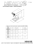
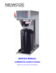
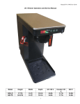
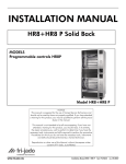
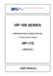
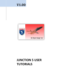
Man Pt No 701859
Rev 3-01
INSTALLATION and OPERATION MANUAL for GXD SERIES BREWERS
GXDF2-30
GXDF-8D
BREWER SPECIFICATIONS
Model
No of
Warmers
Width
Length
Height*
GXDF2-15
GXDF2-30
GXDF-8D
GXDF-8D
2
2
N/A
N/A
19”
19”
19”
19”
19-1/8"
19-1/8"
19-1/8"
19-1/8"
21-3/8”
26-5/8”
30-3/4”
30-3/4”
US
120V
Amps
13.5
14.0
11.5
N/A
US
120/240V
Amps
24.9
25.4
22.9
25.3
Phase
Single
Single
Single
Three (delta)
Shipping weight is approximately 65 pounds for all above units
* Height does not include the 4” adjustable legs. Add approximately 4” to the height shown when using these legs.
NOTE: Automatic models without faucet are also available.
GXD DUAL BREW SYSTEM DESIGN FEATURES
Equipped with a 6.5-gallon hot water tank, the brewer is powered by a 5500 watt, 240-volt element on single-phase units
and three 3500 watt, 240-volt elements on three phase units. A single control board controls water temperature, brew
volume, Visa-Brew, Auto-Arm, and the inlet water valve. Designed to brew simultaneously two separate brews of one,
two or three gallons of hot coffee, the dual brewer also incorporates a hot water faucet.
Timer Controls:
Two independent volume controls for adjusting water volume for the left and right brewing centers. The calibration
system has been streamlined for the service tech with the incorporation of the Auto-Cal feature. To calibrate set the
volume selector switch to the “I” position, turn the brew volume knob clockwise to the maximum setting, which is six (6)
minutes, and initiate brew cycle. Brewer will then deliver water into the coffee or measuring container. Once the correct
volume is reached simply turn the brew volume switch counter-clockwise until the brew stops. The brew volume will now
be calibrated for 1 and 2 volume settings.
Auto-Arm:
The Auto-Arm feature is designed to protect the customer from premature brewing when the water temperature is below
the pre-set optimum brewing temperature setting. When a brew cycle is initiated, before the brew cycle begins Auto-Arm
looks to see if the tank heater is on. If the heater is on Auto-Arm will store the brew cycle signal and begin flashing the
heating and Visa-Brew lights on the front control panel. Once the heater turns off, the brew cycle will automatically begin.
This feature eliminates the need for the customer to check the tank temperature before brewing. When brewing occurs
on both sides, if a brew cycle is initiated while the other side is brewing, Auto-Arm will be disabled, eliminating any
brewing delays.
Visa-Brew:
This feature uses a status brewing light on the left and right brew control center to alert the user that a brew cycle has
either been initiated or is in process and to use caution. This feature also has a calibration adjustment on the control
board, which allows for the calibration to continue the light flashing until the coffee completely drains from the brew
basket. Note: A new brew cycle will not be accepted until the Visa-Light stops flashing. This design eliminates double
brewing. Auto-Cal is incorporated in this system.
Temperature Calibration & Tank System:
The system uses a solid state temperature control to maintain the water temperature in the tank with accuracy inside of
± 3°F. Included in the system is a water detection probe that prevents premature heater turn on when there is no water
present in the tank. Until water makes contact with the probe, the tank heater will not energize. Additionally, a back-up
manual reset limit control has been incorporated into the system, as well as heater run time protection. These features
are designed to protect the equipment in the event of an operator or component failure. For ease of service, access to
the tank is provided from the top of the unit and a top-mounted siphon-drain system is included.
Service Alert System:
The equipment is designed with maximum run time for the heating and water fill system. Listed below is a chart for
interpreting an error code when the brewer will not operate. See brewer “face plate diagram” at rear of manual.
Error Code:
Heating Lamp flashes
continually
Left & Right Visa lights
flash
Right Visa light flashes
Left Visa light flashes
Problem Area:
Water Fill
Tank Heater
Temperature Probe
Temperature Probe
Cause:
System detects that water valve has run
for 6 min. w/o making contact with probe.
Tank heating system has run for 10 min.
w/o a 3 degree change in temperature.
Thermistor is open
Thermistor shorted
Check:
Water supply to brewer, water filters &
water probe to see if limed up.
Tank Heater, Main Thermostat &
Limit Thermostat
Replace Thermistor
Replace Thermistor
IN CASES WHERE THERE IS A HEATER OR FILL PROBE ERROR, THE BREWER CAN BE RESET BY
HOLDING DOWN EITHER BREW START/STOP SWITCH FOR 10 SECONDS. ERROR WILL CLEAR.
2
PLUMBER'S INSTALLATION INSTRUCTIONS (AUTOMATIC BREWERS)
CAUTION: Power to brewer must be OFF before proceeding with plumbing installation.
1) Flush water line before installing brewer. Brewer should be connected to COLD WATER LINE for best operation.
2) Water pressure should be at least 20 lbs. For less than a 25 ft run, use 1/4" copper tubing and connect to 1/2" or
larger water line. For longer runs, use 3/8" copper tubing & connect to 1/2" or larger water line and provide an
adapter fitting for connection to the brewer.
3) If installed with saddle valve, the valve should have a minimum of 1/8" port hole for up to 25 ft run, and 5/16" port
hole for over 25 ft runs.
4) Connect incoming water line to the flow control device on the back of the brewer. Manufacturer recommends
connecting to copper tubing.
ELECTRICAL HOOKUP
WARNING: - Read and follow installation instructions before plugging or wiring in machine to electrical circuit.
Warranty will be void if machine is connected to any voltage other than that specified on the name plate.
Depending on the particular model, this brewer may be hooked up to either a 120/240V ac single phase circuit
or a 120/240V ac three phase delta circuit. Refer to the brewer name plate on back of brewer. The pictorial view at the
bottom of this page illustrates the power cord connection to the terminal block for both circuits. A wiring diagram at the
rear of this manual illustrates the complete brewer wiring. Note that the tank heater system is the only portion of the
brewer running on 240V. The balance of components are powered by 120V obtained by tapping one leg, L1, of the
circuit.
To attach power cord or conduit:
1) Remove the front access panel covering terminal block area by removing the four retaining screws.
2
Locate the strain relief connector on rear of unit and loosen the connectors two screws.
3) Feed appropriate power cord/conduit through the strain relief connector until wire leads reach the terminal block in
front of brewer.
4) Make electrical connections as shown at the bottom of this page and on the wiring diagram at the rear of this
manual. Before attaching leads to terminal block, turn screws on the bottom face of terminal block and on the earth
ground connector fully counter clockwise to insure that the receiver for leads is fully open. Hold lead in place and
tighten by turning screws fully clockwise. Tighten strain relief on rear of unit.
3
INSTALLATION INSTRUCTIONS
WARNING: - Read and follow installation instructions before plugging or wiring in machine to electrical circuit.
1) Place a suitable container in place below the brew basket to catch water. Depress the brew start/stop switch and the
tank will begin to fill. The tank lid has a probe in it to signal the control board when the water has reached the
appropriate level to begin the timing for the brew cycle. If this probe does not see water for 6 minutes the control
board will interpret this as an error. It will shutoff the solenoid valve, disable the control board and the heating light
will flash continually. The time required to fill the tank initially exceeds this time. Therefore this error will occur when
the unit is initially setup. To reset the safety circuit and enable control board simply hold down the brew start/stop
switch for 10 seconds. Error will clear.
2) Depress the brew start/stop switch. The tank lid has a second longer probe in it which is a heater safety probe. This
probe will tell the control board when the water level is high enough to supply power to the tank element. It also will
call for power to be shut off to the element should the water level fall below it. If the tank temperature adjustment is
in the off position or if the autoarm feature has been disabled the unit will continue to fill. Otherwise the brewer will
go into the autoarm mode and the heating light will begin to flash. This indicates that the unit is in the brew mode but
is not up to temperature (Note: To accelerate the set up time the "tank temp" Adjustment dial may be rotated to the
off position momentarily until the fill cycle begins and then turned back). When the tank reaches the preset
temperature the fill portion of the brew cycle will begin. The tank lid must be in place for proper unit operation. When
water begins to flow from brew basket the brew cycle may be canceled by depressing the brew start/stop switch.
Allow water to finish draining from the unit and then empty the container.
3) The GXD Model brewer incorporates an independent manual By-Pass system for the Left and Right brew systems.
By-Pass is turned on to maximum unless customer specified.
Procedure:
a) Remove the top cover and locate the Black adjustment knobs
shown in the figure at right.
b) Turn the knob clockwise to shut off and then counter clockwise 1
¼ turns; this should open the by-pass approximately 10%.
Turning ¼ turn will result in a 5 to 10% increase.
c) To calculate your by-pass, refer to the chart below for available
range.
USE CAUTION WHEN WORKING WITH VERY HOT WATER.
Remove the brew basket from the brew rail and position a metal
container to collect the water from the sprayhead. The by-pass
outlet is located in the right corner of each brew plate. Position a
measuring container under the outlet and initiate a brew cycle,
water will begin to flow out of the sprayhead and by-pass. At the
point the by-pass begins flowing freely, time and collect 30
seconds of water and compare the volume with the chart below
to determine your % of by-pass.
Brew Time
(Water Only)
3:55 min.
3:45 min.
3:35 min.
3:25 min.
3:19 min.
3:12 min.
3:06 min.
3:00 min.
Water
Volume
1 Gal
1 Gal
1 Gal
1 Gal
1 Gal
1 Gal
1 Gal
1 Gal
By-Pass In
30 Seconds
0
1.50 oz.
2.50 oz.
3.25 oz.
4.00 oz.
5.00 oz.
5.70 oz.
6.50 oz.
INSTALLATION INSTRUCTIONS (CONT’D)
4
% Of By-Pass
Total By-Pass
0
10 %
15 %
20 %
25 %
30 %
35 %
40 %
0
12.8 oz.
19.2 oz.
25.6 oz.
32.0 oz.
38.4 oz.
44.8 oz.
51.2 oz.
INSTALLATION INSTRUCTIONS (CONT’D)
4) Once you are satisfied with the by-pass %, you can begin calibrating the brew volume. Set the volume selector
switch to “I”. Depress the brew start/stop switch to resume brewing. After the brew cycle has finished check volume
of water in the container. Adjust the "brew time" with the control board located behind right side access plate. Turn
the dial clockwise to increase the volume of water and counterclockwise to decrease it. The “II” position on the
volume selector switch is automatically set to deliver twice the volume as the “I” position. As an alternate method for
setting brew time: Turn the timer adjustment clockwise to the maximum setting and initiate a brew cycle. When the
water level in the container is reached, slowly turn the timer adjustment counter clockwise until you hear the water
valve turn off. The timer is now set to deliver the volume of water. This Auto Cal feature allows you to streamline the
calibration process. The dial labeled “Visa” on the timer may be set for an additional amount of time to flash the brew
indicator on the face plate to allow time for the coffee to finish draining from the brew basket after the fill cycle has
completed. See Figure below for control board setting information.
5. Allow 10-15 minutes for the water in the tank to heat to brewing temperature. The heating light will go out when the
unit is up to temperature. Run one brew cycle to check for the proper temperature setting with an accurate
thermometer. Take the temperature of this water at a point below the brew basket opening, at the start of the brew
cycle and when the decanter is half full. Recommended temperature of the water is approximately 195 F.
(Note:
Brew cycle may be canceled by depressing the brew start/stop switch). The brewer features an electronic
temperature control circuit and the temperature may be adjusted with the control board located behind the right side
access plate. See Figure below for control board setting information.
6. In higher altitude locations (5000 feet above sea level) the tank temperature may have to be adjusted lower to
prevent boiling. Turning adjustment knob in a clockwise direction will increase water temperature. This unit features
an electronic temperature control. Adjustment is located on the control board behind the right side access plate.
7. CAUTION: The water faucet will dispense hot water when the handle is pulled.
WARRANTY
Newco coffee brewers are warranted against defects in workmanship or materials, under normal use, for 90 days from
the date of purchase. Brewer parts are warranted against defect for 12 months from date of purchase.
Liability in all events is limited to the purchase price paid and liability under the aforesaid warranty is limited to replacing
or repairing any part or parts which are defective in material or workmanship, and returned to our factory, shipping cost
prepaid. No warranty expressed or implied, other than the aforesaid is made or authorized by Newco Enterprises, Inc.
Prompt disposition will be made if item proves to be defective, within warranty. Before returning any item, write or call
Newco, or the dealer, from whom the product was purchased, giving model number, serial number, and date of
purchase, and describe the nature of the defect. If damage was incurred during transit to you, file claim with the carrier
5
COFFEE PREPERATION PROCEDURES
1) Place filter into brew basket.
2) Put the appropriate amount of ground coffee into the filter for the volume of coffee being brewed.
3) Slide the brew basket into holder.
4) Set the volume selection switch to the appropriate position for the volume of coffee being brewed.
5) For warmer units:
Place empty decanter on warmer located directly under the brew basket.
Turn corresponding warmer switch to ON position.
For dispenser units:
Remove the dispenser lid unless it is a brew through design.
Place the dispenser directly under the brew basket.
6) Press brew start/stop switch. Note: a brew cycle may be initiated even if the heating light is on.
7) If the autoarm feature is enabled the heating light will begin to flash indicating that the brewer is heating and will
begin to brew immediately after the heating cycle is complete. Do not remove decanter. Brew cycle may be canceled
by depressing the brew start/stop switch. The heating light should no longer be flashing.
8) Hot water will be delivered through the sprayhead. This distributes the hot water evenly over the coffee bed within
the brew basket. The coffee brew will drain from the brew basket into the decanter below.
9) The status brewing light should continue to flash until all the liquid has finished flowing from the brew basket. Do not
remove decanter until the brewing process has stopped and all liquid has stopped flowing from the brewbasket.
10) The resultant coffee brew should be crystal clear and have the desired properties attainable through excellent
extraction.
11) To clean brew basket simply remove from brew rails and dump filter into wastebasket. The brewing process, as
described above, can now be started again.
GXD SERIES REPLACEMENT PARTS LIST
110307
100251
152114
102770
701985
701483
100025
701870
701875
701286
701760
701690
701619
701695
701305
PDS Valve Assembly, High Flow
Valve, Solenoid, Hemco
Dump Valve, Solenoid
Faucet Assembly
Tube Assembly, Sprayhead
Sprayhead Assembly
Gasket, Sprayhead
Tank Assembly, 5500W/240V, 1 Phase
Tank Assembly, 10500W/240V, 3 Phase
Tank Element, 5500W/240V
Tank Element, Five Loop, 3500W/240V
Tank Element, Triple Loop, 3500W/240V
Tank Element, 6000W/208V
Tank Element, 6600W/240V
Thermostat, Manual Reset
108143
108225
100008
202053
110959
102841
201985
700434
100085
701449
100236
701714
701713
701527
6
Control Board (A)
Control Board (B)
Warmer Plate, Black Porcelainized
Element, Warmer, 120W/120V (Mod -15)
Element, Warmer, 150W/120V (Mod -30)
Micro Switch, Faucet
Switch, Start, Black
Switch, SPST Black (I, II Volume Select)
Switch, Lighted SPST, Red Rocker
Light, Visa, Red
Light, Heating
Brew Basket, Plastic
Brew Basket, S/S
Brew Basket, Gourmet, S/S
FACE PLATE DIAGRAM
(MODEL GXDF-8D)
WIRING DIAGRAM
Newco Enterprises, Inc. * 1735 South River Rd. * P.O. Box 852 * St. Charles, MO 63303
7