1
HP Archive
This vintage Hewlett Packard document was preserved
and distributed by
www.hparchive.com
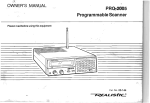
Please visit us on the web !
Thanks to on-line curator: Kenneth Kuhn for supplying and
scanning this vintage document.
l,
HEWLETT-PACKARD COMPANY
739AR
FREQUENCY
RESPONSE TEST 'SET
OPERATING AND SERVICE MANUAL
MODEL 739AR
SER IALS PREFIXED:
010-
FREQUENCY RESPONSE
TEST SET
Copyright
HEWLETT-PACKARD COMPANY
1959
1501 PAGE Mll..L ROAD, PALO ALTO, CALIFORNIA, U. S. A.
00203·2
Printed: NOY 1961
Section I
Model 739AR
\
RANGE SELECTOR
fREQ TUNING
010. AA(Q MC3~1
1~3
OUTPUT
.,.
ATTENUATOR
{YTVM. aoAL.£l
oQI..
INPUT
POWER
ON
I AWP
AWPUTUDE
....
COl
FREQUENCY RESPONSE
TEST SET
.......
tW:Wt£tT
~-
~
OUTPUT
" ....
PACXAIlO
....-
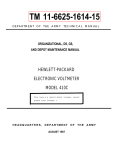
Figure 1. Model 739AR Frequency Response Test Set
1-0
00203-2
Model 739AR
Section I
SECTION I
DESCRIPTION
The t5jJ Model 739AR Frequency Response Test Set
simplifies frequency response determination by providing a convenient constant amplitude reference
voltage of variable frequency. Frequency response
of vacuum tube voltmeters, oscilloscopes, video amplifiers and filters from 5 cps to 10 mc (extended
frequency range when used with tEjJ Model 200S Oscillator) can be quickly and easily checked.
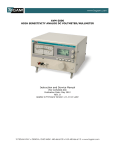
The Frequency Response Test Set contains a wide
range oscillator, special voltmeter, and step attenuator as shown in figure 2. The oscillator generates
constant amplitude signals between 300 kc and 10 mc.
The monitoring circuit is flat from 5 cps to 10 mc
so that an external oscillator such as tEjJ Model 200S
can be used to reduce the lower frequency limit to
as low as 5 cps. Oscillator output is applied to the
monitoring voltmeter, which samples the input to a
step attenuator.
An arbitrary reference level is
maintained on the monitoring meter as the frequency
setting is varied. The attenuator reduces the signal
to an appropriate output level which appears across
50 ohms at the end of the special output cable supplied.
0-70db
ATTEN.
10db STEPS
INT. OSC.
.30-10 MC
METER
SET
I...
50
~
e:
~
I'
<:)
MONITOR
METER
EXT. INPUT
5cps-300KC
RO
Figure 2. Model 739AR Block Diagram
Table 1. Specifications
FREQUENCY RANGE: 300 kc to 10 mc in 3 ranges.
(5 cycles to 10 mc with Model 200SR Oscillator)
DIMENSIONS: Rack Mount
REQUIREMENTS FOR EXTERNAL OSCILLATOR:
3 volts into 50 ohms,S cps to 300 kc, distortion
less than 1%
FREQUENCY RESPONSE OF MONITORING CIRCUIT: Flat within ± 0.5% from 10 cps to 5 mc;
within +0.5%, -1.5%, 5 cps to 10 mc. Monitor
circuit is average reading.
OUTPUT: At least 3 volts across 50-ohm cable
termination. Adjustable in 10 db steps by a 0 to
70 db attenuator.
Fine adjustrpent provided.
POWER: 115 or 230 volts ± 10%, 5@ to 1000 cps,
30 watts.
WEIGHT: Net 14 lb, shipping 28 lb
00203-2
Il!-
j'
-.
'-.r-.,....~=====;-,
REAR
--1
f-1~'~-=--=-\-_-_-19- _-_-_-_...J_~~.I1t
739AR
64
ACCESSORIES FURNISHED:
739A-16A 30 inch
Output Cable, 50-ohm termination. BNC to
shielded dual banana plug, (extra cables available
on special order).
1-1/1-2
Model 739AR
Sections I1 and III
SECTION II
OPERATION
Calibrate the device under test with an accurate voltage standard, such as the <fj; Model 738A Voltmeter
Calibrator. This voltage standard should have an
output frequency between 100 and 1000 cps.
a. Connect the device under test to the Frequency
Response Test Set OUTPUT connector, using thespecial terminated output cable provided.
b. Connect a suitable oscillator, such as the <fj; Model
200S Oscillator, to the EXTERNAL INPUT connector
on the Frequency Response Test Set.
c. Set the external oscillator to the frequency used
for calibration.
d. Set the RANGE SELECTOR to EXTERNAL. Set
a reference on the device under test using the external
oscillator AMPLITUDE control and the OUTPUT ATTENUATOR of the test set.
NOTE: Always use the OUTPUT ATTENUA1'TIRrange that corresponds to the desired input to the device under test. This will assure
a test set meter indication near SET LEVEL.
e. Set the meter in the test set to SET LEVEL with
the METER SET control,
f. Shift to any other frequency within the range of
the test set or external oscillator. Return the meter
to SET LEVEL using the oscillator AMPLITUDE control. Note any deviation from the reference set in
step d on the device under test.
g. Repeat steps c through f if you change the range
switch on the device under test. Repeat stepf for all
frequencies you desire to check.
SECTION III
MAINTENANCE
The internal oscillator is a single pentode (V2) located
inside the shield on top of the chassis. The oscillator
plate and screen voltages are controlled by a series
regulator triode (VI). This series regulator is controlled by a two stage differential amplifier (V3 and
V4) that senses the amplitude of the voltage applied
to the OUTPUT ATTENUATOR. The combined action
of the series regulator, differential amplifier and output amplitude sensing circuits keeps the output constant over the range of the internal oscillator.
The power supply circuit is conventional, using glow
00203-2
discharge tubes to regulate the differential amplifier
voltages. Tube element voltages are not listed on the
schematic diagram since they vary radically with frequency and output AMPLITUDE control setting.
The only adjustments in the oscillator circuit are for
initial dial calibration and should not need further
attention. Another adjustment (CI6) is provided in
the meter circuit. This meter frequency response
adjustment should not be touched unless you have accurate means of checking the accuracy of the reference
meter between 7 and 10 mc.
2-1
3-1
tv
I
u.>
o
o
tv
o
tv
I
u.>
SWITCH POSITONS OF
I EXTERNALI
Ll
10PH
4
t::::E:!§J
3.~
2.0::=:0
1.
I'~ _
~ __
i
Q SIA,B,C.O.E (GANGED)
IftOlnt.naRce
of
H~I.".'odcotd
"';0 I,~,""" I
T3U.:"T-OIOB
Hewlett.packord Company.
I
RI
33
,
"
II'
~
"f-------"-> "
,
,
,
g>
eqUip·
SIA
.I
r
(2
, (3
,
I
OA2
VR4
., OB2
VR3
OB2
VR2
VRl
., OA2
r250V
-250V
VOLTAGE
REGULATOR
CI4
820
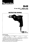
Model 739AR Frequency Response Test Set
1(4~
Figure 3.
1'</,
C5
.OIj.1F
J J
o
4~
0
"CD
,
,
- ---
men' and I, not to b. v.ed oth.rwJ.. or
r.produced wlthoyt written con..nt of th.
and
Thl, drawing I. Intended for the operation
COPYRIGHT 19n IV HEWLm.PACKAltD COMPANV
CI5
820
Section IV
Model 739AR
SECTION IV
REPLACEABLE PARTS
This section contains iriformation for ordering replacement parts for the Model 739AR Frequency Response Test Set.
Table 2 lists replaceable parts in alpha-numerical
order of their reference designators. Detailed information on a part used more than once in the instrument is listed opposite the first reference designator
applying to the part. Other reference designators
applying to the same part refer to the initial designator. Miscellaneous parts are included at the end of
the list. Detailed information includes the following:
a. Reference designator.
To order a replacement part, address order or inquiry
either tofyour authorized Hewlett-Packard sales representative or to
CUSTOMER SERVICE
Hewlett-Packard Company
395 Page Mill Road
Palo Alto, California
or, in Western Europe, to
Hewlett-Packard S.A.
Rue du Vieux Billard No. 1
Geneva, Switzerland
Specify the following information for each part:
b. Full description of the part.
a. Model and complete serial number of instrument.
c. Manufacturer of the part in a five-digit code;
see list of manufacturers in appendix.
b. Hewlett-Packard stock number.
c. Circuit reference designator.
d. Hewlett-Packard stock number.
d. Description.
e. Total quantity used in the instrument (TQ col).
f. Recommended spare quantity for complete maintenance during one year of isolated service (RS col).
To order a part not listed in table 2, give a complete
description of the part and include its function and
location.
Table 2. Replaceable Parts
Description
Ckt Ref.
Mfr
rEfJ Stock No.
TQ
RS
Cl
Capacitor: variable, air dielectric,
2 section, 9.5-443.2 pf
76854
0121-0026
1
1
C2
Capacitor: variable, ceramic,
7-45 pf, 500 vdcw
72982
0130-0001
1
1
C3, 4
Capacitor: variable, ceramic, 1 section
1. 5-7 pf, 500 vdcw
72982
0130-0003
2
1
C5
Capacitor: fixed, ceramic,
.01 J.Lf ± 20%, 1000 vdcw
71590
0150-0012
10
3
C6
Capacitor: fixed, ceramic
1000 pf ± 25%, 500 vdcw
96095
0150-0005
1
1
C7
Same as C5
C8
Capacitor: fixed, mica,
100 pf ± 5%, 500 vdcw
76433
0140-0041
1
1
C9 thru
Cll
00203-2
Same as C5
4-1
Section IV
Model 739AR
Table 2. Replaceable Parts (Continued)
Ckt Ref.
Description
Mfr *
<&; Stock No.
TQ* RS*
C12, 13,
14, 15
Capacitor: fixed, mica,
820 pf ± 10%, 500 vdcw
76433
0140-0010
4
1
C16
Capacitor: variable, polystyrene
0.7-3 pf, 350 vdcw
72982
0132-0002
1
1
C17
Capacitor: fixed, titanium dioxide,
1 pf ± 10%, 500 vdcw
Optimum value selected at factory.
Average value shown.
82142
0150-0029
1
1
C18, 19
Same as C5
C20, 21
Capacitor: electrolytic, 2 sections,
20 /If/sect., 450 vdcw
56289
0180-0012
2
1
C22, 23,
24
Same as C5
CRl, 2
Diode, germanium
73293
1910-0011
2
2
CR3, 4
Diode, silicon
73293
1901-0027
2
2
DSI
Lamp, miniature: 2 pin base, #12
24455
2140-0012
1
1
Fl
Fuse: 1 amp slow blow, for 115 V
operation
71400
2110-0007
1
10
Fuse: 1/2 amp, slow blow, for 230 V
operation
71400
2110-0008
1
0
Jl
Connector: part of Ext. Input Cable
J2
Connector: part of Output Cable
Ll, 2
Inductor, RF; 10 J1.h ± 10%
99848
9140-0032
2
1
Ml
Meter
65092
1120-0091
1
1
PI
Cable, power
70903
8120-0015
1
1
Rl
Resistor: fixed, composition,
33 ohms ± 10%, 1 W
01121
0690-3301
1
1
R2
Resistor: fixed, composition,
1000 ohms ± 10%, 1 W
01121
0690-1021
1
1
R3
Resistor: fixed, composition,
1000 ohms ± 10%, 1/2 W
01121
0687-1021
1
1
R4
Resistor: fixed, composition,
68, 000 ohms ± 10%, 1 W
01121
0690-6831
1
1
* See introduction to this section
4-2
00203-2
Mode1739AR
Section IV
Table 2. Replaceable Parts (Continued)
Ckt Ref.
Description
Mfr *
<&> Stock No.
TQ* RS*
R5
Resistor: fixed, c,Jmposition,
1 megohm ± 10%, 1/2 W
01121
0687-1051
1
1
R6
Resistor: fixed, deposited carbon,
667, 000 ohms ± 1%, 1/2 W
19701
0727-0249
2
1
R7
Resistor: fixed, composition,
470,000 ohms ± 10%, 1/2 W
01121
0687-4741
1
1
R8
Resistor: fixed, deposited carban,
4 megohms ± 1%, 1/2 W
19701
0727-0298
2
1
R9
Resistor: fixed, deposited carbon,
5.55 megohms ± 1%, 1/2 W
19701
0727-0300
2
1
RIO
Resistor: fixed, composition,
220,000 ohms ± 5%, 1/2 W
01121
0686-2245
1
1
Rll
Same as R6
R12
Same as R8
R13
Same as R9
R14
Resistor: fixed, deposited carbon,
600,000 ohms ± 1%, 1/2 W
19701
0727-0246
1
1
R15
Resistor: fixed, deposited carbon,
2 megohms ± 1%, 1/2 W
19701
0727-0287
1
1
R16
Resistor: variable, composition,
100,000 ohms, linear taper
11237
2100-0063
1
1
R17
Resistor: fixed, composition,
47,000 ohms ± 10%, 1/2 W
01121
0687-4731
1
1
R18, 19
Resistor: fixed, composition,
1 megohm ± 10%, 1/2 W
01121
0687-1051
2
1
R20, 21
Resistor: fixed, deposited carbon,
5030 ohms ± 1%, 1/2 W
19701
0727-0136
2
1
R22
Resistor: variable, composition,
linear taper, 500 ohms ± 10%
71590
2100-0019
1
1
R23
Resistor: fixed, deposited carbon,
300 ohms ± 1%, 1/2 W
Optimum value selected at factory.
Average value shown.
19701
0727-0065
1
1
R24, 25
Resistor: fixed, deposited carbon,
201 ohms ± 1%, 1/2 W
19701
0727-0055
2
1
R26, 27
Resistor: fixed, composition,
12,000 ohms ± 10%, 2 W
01121
0693-1231
2
1
Sl
Switch, rotary: 2 sect. 4 pos
76854
3100-0085
1
1
S2
Switch, toggle: SPST, 250 V, 3 amp
04009
3101-0001
1
1
.
* See introduction to this section
00203-2
4-3
Section N
Model 739AR
Table 2. Replaceable Parts (Continued)
Ckt Ref.
Description
Mfr *
~
Stock No.
TQ* RS*
SRI
Rectifier, metal
162 V rms max, 20 rna dc max
77638
1883-0005
1
1
Tl
Transformer, RF
28480
739A-60A
1
1
T2
Transformer, RF
28480
739A-60B
1
1
T3
Transformer, RF
28480
739A-60C
1
1
T4
Transformer, power
98734
9100-0027
1
1
VI
Tube, electron: 6C4
86684
1921-0005
1
1
V2
Tube, electron: 6AQ5
82219
1923-0018
1
1
V3, 4
Tube, electron: 12AX7
00001
1932-0030
2
2
V5
Tube, electron: 6X4
33173
1930-0016
1
1
VRI
Tube, electron: voltage regulator, OA2
86684
1940-0004
2
2
VR2, 3
Tube, electron: voltage regulator, OB2
86684
1940-0007
2
2
VR4
Same as VRI
Attenuator assembly
28480
739A-34
1
1
Cable assembly: Ext. Input
28480
739A-16B
1
0
Cable assembly: Output
28480
739A-16A
1
1
Fuseholder: extractor post type
75915
1400-0084
1
1
Knob: METER SET
28480
G-74C
2
0
Knob: AMPLITUDE
28480
G-74F
1
0
Knob: RANGE SELECTOR,
OUTPUT ATTENUATOR
28480
G-74N
2
0
MISCE LLANEOUS
* See introduction to this section
4-4
00203-2
Model 739AR
Appendix
APPENDIX
CODE LIST OF MANUFACTURERS (Sheet 1 of 2)
The following code numbers are from the Federal Supply Code for Manufacturers Cataloging Handbooks H4-' (Name to Code)
and H4-2 (Code to Name) and their latest supplements. The date of revision and the date of the supplements used appear at
the bottom of each page. Alphabetical codes have been arbitrarily assigned to suppliers not appearing in the H4 handbooks.
CODE
NO.
MANUFACTURER
ADDRESS
00334 Humidial Co.
Colton, Calif.
New York. N.Y.
00335 Wesfrex Corp.
00373 Garlock Packing Co.,
Electronic Products Div.
Camden, N.J.
New Bedford, Mass.
00656 Aerovax Corp.
Harrisburg, Pd.
00779 Amp. Inc.
Boonton, N.J.
00781 Aircraft Radio Corp.
00853 Sangamo Electric Co., Cap. Div.
Marion, III.
Los Angeles, Calif.
00866 Goe Engineering Co.
Carl
E.
Holmes
Corp.
Los
Angeles,
Calif.
00891
Milwaukee, Wis.
01 1 2 1 Allen Bradley Co.
Beverly Hills, Calif.
01 255 Litton Industries, Inc.
01 281 Pacific Semiconductors, Inc.
Culver City, Calif.
o 1 2 9 5 T.xas I nstruments, Inc.
Semiconductor Components Div.
Dallas, Texas
Alliance, Ohio
01 349 The Alliance Mfg. Co.
01 561 Cha..i·Trak Corp.
Indianapolis, Ind.
Rockford, III.
01 930 Amerock Corp.
Santa Clara, Calif.
01 961 Pulse Engineering Co.
021 1 4 Ferroxcube Corp. of America
Saugerties, N.Y.
Palo Alto, Calif.
02286 Cole Mfg. Co.
Chicago, Ill.
02660 Amphenol Electronics Corp.
02735 Radio Corp. of America
Semiconductor and Materials Div.
Somerville, N.J.
02771 Vocaline Co. of America, Inc.
Old Saybrook, Conn.
02777 Hopkins Engineering Co.
San Fernando, Calif.
o 3 508 G.E. Semiconductor Products Dept.
Syracuse, N.Y.
Dayton, Ohio
03705 Apex Machine & Tool Co.
03797 Eldema Corp.
EI Monte, Calif.
03877 Transitron Electronic Corp. Wakefield, Mass.
03888 Pyrofilm Resistor Co.
Morristown, N.J.
03954 Air Marine Motors, Inc.
Los Angeles, Calif.
04009 Arrow, Hart and Hegeman Elect. Co.
Hartford, Conn.
04062 Elmenco Products Co.
New York, N.Y.
04222 Hi-9 Division of Aerovox Myrtle Beach, S.C.
04298 Elgin National Watch Co.,
Electronics Division
Burbank, Calif.
a 4 4 0 4 Oymec Division of
Hewlett·Packard Co.
Palo Alto, Calif.
04651 Special Tube Operations of
Sylvania Electronic S~~u~:ain View, Calif.
a 471
3
04732
a4 7 7 3
D5 aa 6
a5 2 7 7
as 5 9 3
05624
a5 7 2 9
05783
06004
06555
0681 2
o7 1 1 5
Motorola, Inc., Semiconductor
Prod. Div.
Phoenix, Arizona
Filtron Co., Inc.
Western Division
Culver City, Calif.
Automatic Electric Co.
Northlake, Ill.
Twentieth Century Plastics, Inc.
Los Angeles, Calif.
Westinghouse Electric Corp.,
Semi·Conductor Dept.
Youngwood, Pa.
Jllumitronic Engineering Co.
Sunnyvale, Calif.
Barber Colman Co.
Rockford, III.
Metropolitan Telecommunications Corp.,
Metro Cap. Div.
Brooklyn, N.Y.
Stewart Engineering Co.
Soquel, Calif.
The Bassick Co.
Bridgeport, Conn.
Beede Electrical Instrument Co., Inc.
Penacook, N.H.
Torrington Mfg. Co., West. Div.
Van Nuys, Calif.
Corning Glass Works
Electronic Components Dept.
Bradford, Pa.
CODE
NO.
MANUFACTURER
071 26 Digitran Co.
Pasadena, Calif.
071 37 Transistor Electronics Corp.
Minneapolis, Minn.
071 38 Westinghouse Electric Corp.
Electronic Tube Div.
Elmira, N.Y.
07261 Avnet Corp.
Los Angeles, Calif.
07263 Fairchild Semiconductor Corp.
Mountain View, Calif.
0791 0 Continental Device Corp. Hawthorne, Calif.
07933 Rheem Semiconductor Corp.
Mountain View, Calif.
07980 Boonton Radio Corp.
Boonton, N.J.
081 45 U.S. Engineering Co.
Los Angeles, Calif.
08358 Burgess Battery Co.
Niagara Falls, Ontario, Canada
0871 7 Sloan Company
Burbank, Calif.
0871 8 Cannon Electric Co.
Phoenix Div.
Phoenix, Ariz.
08792 CBS Electronics Semiconductor
Operations, Div. of C.B.S. Inc.
Lowell, Mass.
09026 Babcock Relays, Inc.
Costa Mesa, Calif.
091 34 Texas Capacitor Co.
Houston , Texas
09250 Electro Assemblies, Inc.
Chicago, III.
09569 Mallory Battery Co. of
Canada, Ltd.
Toronto, Ontario, Canada
1 041 1 Ti-Tal, Inc.
Berkeley, Calif.
1 0646 Carborundum Co.
Niagara Falls, N.Y.
11236 CTS of Berne, Inc.
Berne, Ind.
1 1 237 Chicago Telephone of California, Inc.
So. Pasadena, Calif.
1 1 31 2 Microwave Electronics Corp.
Palo Alto, Calif.
1 1 870 Melabs, Inc.
Palo Alto, Calif.
126 9 7 Clarostat Mfg. Co.
Dover, N.H.
1 4655 Cornell Dubilier Elec. Corp.
So. Plainfield, N.J.
1 5909 The Daven Co.
Livingston, N.J.
1 6758 Delco Radio Div. of G. M. Corp.
Kokomo, Ind.
1 8873 E. I. DuPont and Co., Inc.
Wilmington, Del.
19315 Eclipse Pioneer, Div. of
Bendix Aviation Corp.
Teterboro. N.J.
1 9500 Thomas A. Edison Industries,
Div. of McGraw-Edison Co.
West Orange, N.J.
1 9701 Electra Manufacturing Co. Kansas City, Mo.
201 83 Electronic Tube Corp.
Philadelphia, Pa.
21 520 Fansteel Metallurgical Corp.
.
No. Chicago, III.
21 335 The Fafnir Bearing Co.
New Britain, Conn.
21 964 Fed. Telephone and Radio Corp.
Clifton, N.J.
24446 General Electric Co.
Schenectady, N.Y.
24455 G. E., Lamp Division
Nela Park, Cleveland, Ohio
24655 General Radio Co.
West Concord, ~ass.
26462 Grobet File Co. of America, Inc.
Carlstadt, N.J.
26992 Hamilton Watch Co.
Lancaster, Pa.
28480 Hewlett-Packard Co.
Palo Alto, Calif.
33173 G. E. Receiving Tube Dept. Owensboro, Ky.
35434 Lectrohm Inc.
Chicago, III.
37942 P. R. Mallory & Co., Inc. Indianapolis, Ind.
39 5 4 3 Mechanical Industries Prod. Co.
Akron, Ohio
40920 Miniature Precision Bearings, Inc.
Keene, N.H.
421 90 Muter Co.
Chicago, III.
43990 C. A. Norgren Co.
Englewood, Colo.
44655 Ohmite Mfg. Co.
Skokie, III.
47904 Polaroid Corp.
Cambridge, Mass.
00015·16
Revised: 20 September 1961
00203-2
ADDRESS
CODE
NO.
48620
499 5 6
54294
55026
55933
55938
561 37
56289
59446
61 775
621 1 9
64959
65092
MANUFACTURER
ADDRESS
Precision Thermometer and
Inst. Co.
Philadelphia, Pa.
Raytheon Mfg. Co.
Waltham, Mass.
Shallcross Mfg. Co.
Selma, N.C.
Simpson Electric Co.
Chicago, III.
Sonotone Corp.
Elmsford, N.Y.
Sorenson & Co., Inc.
So. Norwalk, Conn.
Spaulding Fibre Co., Inc. Tonawanda, N.Y.
Sprague Electric Co.
North Adams, Mass.
St. Paul, Minn.
Telex, Inc.
Union Switch and Signal,
Div. of Westinghouse Air Brake Co.
Pittsburgh, Pa.
Universal Electric Co.
Owosso, Mich.
Western Electric Co., Inc.
New York, N.Y.
Weston Inst. Div. of Daystrom, Inc.
Newark, N.J.
Wollensak Optical Co.
Rochester, N.Y.
Allen Mfg. Co.
Hartford, Conn.
66346
70276
70309 Allied Control Co., Inc.
New York, N.Y.
70485 Atlantic India Rubber Works, Inc.
Chicago, III.
70563 Amperite Co., Inc
New York, N.Y.
70903 Belden Mfg. Co.
Chicago, III.
Cleveland, Ohio
70998 Bird Electronic Corp.
71 002 Birnbach Radio Co.
New York, N.Y.
71 21 8 Bud Radio Inc.
Cleveland, Ohio
Paramus, N.J.
71 286 Camloc Fastener Corp.
71 31 3 Allen D. Cardwell Electronic
Prod. Corp
Plainville, Conn.
71 4 0 Bussmann Fus~ Div. of McGrawEdison Co.
St. Louis, Mo.
71 450 CTS Corp.
Elkhart, Ind.
71 468 Cannon Electric Co.
Los Angeles, Calif.
71 471 Cinema Engineering Co.
Burbank, Calif.
71 482 C. P. Clare & Co.
Chicago, III.
71 590 Centralab Div. of Globe Union Inc.
Milwaukee, Wis.
71 700 The Cornish Wire Co.
New York, N.Y.
7 1 744 Chicago Miniature Lamp Works
Chicago, III.
71 753 A. O. Smith Corp.• Crowley Div.
West Orange, N.J.
7 1 785 Cinch Mfg. Corp.
Chicago, III.
71 984 Dow Corning Corp.
Midland, Mich.
721 36 Electro Motive Mfg. Co., Inc.
Willimantic, Conn.
72354 John E. Fast & Co.
Chicago, III.
7261 9 Dialight Corp.
Brooklyn, N.Y.
72656 General Ceramics Corp.
Keasbey, N.J.
72758 Girard-Hopkins
Oakland, Calif.
72765 Drake Mfg. Co.
Chicago, III.
72825 Hugh H. Eby Inc.
Philadelphia, Pa.
729 2 8 Gudeman Co.
Chicago, III.
729 8 2 Erie Resistor Corp.
Erie, Pa.
73061 Hansen Mfg. Co., Inc.
Princeton, Ind.
73138 Helipot Div. of Beckman
Fullerton, Calif.
Instruments, Inc.
7 3 2 9 3 Hughes Product.
DIV. of Hughes Aircraft Co.
Newport Beach, Calif.
73445 Amperex Electronic Co., Div. of
North American Phillips Co., Inc.
Hicksville, N.Y.
73506 Bradley Semiconductor Corp.
New Haven, Conn.
73559 Carling Eiectric, Inc.
Hartford, Conn.
73682 George K. Garrett Co., Inc.
Philadelphia, Pa.
7 3 7 4 3 Fischer Special Mfg. Co.
Cincinnati, Ohio
73793 The General Industries Co.
Elyria, Ohio
a
From: F.S.C. Handbook Supplements
H4-1 Dated April 1961
H4-2 Dated April 1961
i-l
Appendix
Model 739AR
APPENDIX
CODE LIST OF MANUFACTURERS (Sheet 2 of 2)
CODE
NO.
MANUFACTURER
ADDRESS
San Jose, Calif.
739 0 5 Jennings Radio Mfg. Co.
74455 J. H. Winns, and Sons
Winchester, Mass.
Chicago, 111.
74861 Industrial Condenser Corp.
74868 Industrial Products Co.
Danbury, Conn.
749 7 0 E. F. Johnson Co.
Waseca, Minn.
75042 International Resistance Co.
Philadelphia, Pa.
751 73 Jones, Howard B., Division
of Cinch Mfg. Corp.
Chicago, 111.
75378 James Knights Co.
Sandwich, 111.
75382 Kulka Electric Mfg. Co., Inc.
Mf. Vernon, N.Y.
Chicago, 111.
75818 lent. Electric Mfg. Co.
7591 5 littelfuse Inc.
Des Plaines, III.
Erie, Pa.
76 005 lord Mfg. Co.
San Francisco, Calif.
76 210 C. W. Marwedel
76433 Micamold Electronic Mfg, Corp.
8rooklyn, N.Y.
76487 James Millen Mfg, Co., Inc. Malden, Mass.
San 'Leandro, Calif.
76530 Monadnock Mills
Cleveland, Ohio
76 5 4 5 Mueller Electric Co.
76854 Oak Manufacturing Co.
Chicago. 111.
77068 Bendix Corp., Bendix
Pacific Div.
No. Hollywood, Calif.
77221 Phaostron Instrument and
Electronic Co.
South Pasadena, Calif.
Princeton, Ind.
77342 Potter and Brumfield, Inc.
Camden, N.J.
77630 Radio Condenser Co.
77 6 34
77 638
77764
78283
78471
78488
78553
78790
78947
791 42
79251
79963
80031
80130
801 31
80207
80248
80411
8048 6
80583
80640
81 030
81 41 5
81453
81 483
81 860
82042
82142
821 70
82209
8221 9
82376
Radio Essentials Inc.
Mt. Vernon, N.Y.
Brooklyn, N.Y.
Radio Receptor Co., Inc.
Harrisburg, Pa.
Resistance Products Co.
Signal Indicator Corp.
New York, N.Y.
San Francisco, Calif.
Tilley Mfg. Co.
St. Marys, Pa.
Stackpole Carbon Co.
Tinnerman Products, Inc.
CleYeland, Ohio
Transformer Engineers
Pasadena, Calif.
Ucinite Co.
Newtonville, Mass.
Veeder Root, Inc.
Hartford, Conn.
Chicago, III,
Wenco Mfg. Co.
Zierick Mfg. Corp.
New Rochelle, N.Y.
Mepco Division of
Sessions Clock Co.
Morristown, N.J.
Times Facsimile Corp.
New York, N.Y.
Electronic Industries Association
Any brand tube meeting EIA
standards
Washington, D.C.
Unimax Switch, Div. of
W. l. Maxson Corp.
Wallingford, Conn.
Oxford Electric Corp.
Chicago, 111.
Aero Manufacturing Co.
Columbus, Ohio
All Star Producls Inc,
Defiance, Ohio
Hammer/und Co., Inc.
New York, N.Y.
Stevens, Arnold, Co., Inc.
Boston, Mass.
International Instruments, Inc.
New Haven, Conn.
Wilkor Producls, Inc.
CleYeland, Ohio
Raytheon Mfg. Co" Industrial
Tube Division
Quincy, Mass.
International Rectifier Corp.
EI Segundo, Calif.
Barry Controls, Inc.
Watertown, Mass.
Carter Parts Co.
Skokie, III:
Jeffers Electronics Division of
Speer Carbon Co.
Du Bois, Pa.
Allen B. DuMont Labs., Inc.
Clifton, N.J.
Maguire Industries, Inc.
Greenwich, Conn.
Sylvania Electric Prod. Inc.,
Emporium, Pa.
Electronic Tube Div.
East Newark, N.J.
Astron Co.
CODE
NO.
MANUFACTURER
Chicago, III.
82389 Switchcraft, Inc.
82647 Texas Instruments, Inc.,
Metals and Controls Div.,
Spencer Products
Attleboro, Mass.
82866 Research Products Corp.
Madison, Wis.
82877 Rotron Manufacturing Co., Inc.
Woodstock, N.Y.
82893 Vector Electronic Co.
Glendale, Calif.
Los Angeles, Calif.
83148 Electro Cords Co.
Union, N.J.
831 86 Victory Engineering Corp.
8329 8 Bendix Corp., Red 8ank Diy. Red Bank, N.J.
83594 Burroughs Corp.,
Plainfield, N.J.
Electronic Tube Div.
83777 Model Eng. and Mfg., Inc.
Huntington, Ind.
Festus, Mo.
83821 loyd Scruggs Co.
New York, N.Y.
841 71 Arco Electronics, Inc.
8439 6 A. J. Glesener Co., Inc.
San Francisco, Calif.
8441 1 Good All Electric Mfg. Co. Ogallala, Neb.
Bloomington, Ind.
84970 Sarkes Tanian, Inc.
Boonton, N.J.
85454 Boonton Molding Company
85474 R. M. Bracamonte & Co.
San Francisco, Calif.
New Haven, Conn.
85660 Koiled Kords, Inc.
Chicago, III.
8591 1 Seamless Rubber Co.
Radio
Corp.
of
America,
RCA
86684
Electron Tube Div.
Harrison, N.J.
87473 Western Fibrous Glass Products Co.
San Francisco, Calif.
Lincoln, 111.
881 40 Cutler-Hammer, Inc.
89473 General Electric Distributing Corp.
Schenectady, N.Y.
901 79 U.S. Rubber Co., Mechanical
Goods Div.
Passaic, N.J.
90970 Bearing Engineering Co. San Francisco, Calif.
Chicago, Ill.
91 41 8 Radio Materials Co.
91 506 Augat Brothers, Inc.
Attleboro, Mass.
Columbus, Neb.
91 637 Dale Products, Inc.
91662 Elco Corp.
Philadelphia, Pa.
Wakefield, Mass.
91737 Gremar Mfg. Co., Inc.
91 827 K F Development Co. Redwood City, Calif.
91929 Micro-Switch Div. of Minneapolis
Honeywell Regulator Co.
Freeport, Ill.
92196 Universal Metal Products, Inc.
Bassett Puente, Calif.
93 3 3 2 Sylvania Electric Prod. Inc.,
Semiconductor Div.
Woburn, Mass.
New York, N.Y.
93 36 9 Robbins and Myers, Inc.
9341 0 Stevens Mfg. Co., Inc.
Mansfield, Ohio
93983 Insuline·Van Norman Ind., Inc.
Electronic Division
Manchester, N.H.
9414 4 Raytheon Mfg. Co., Receiving
Tube Div.
Quincy, Mass.
941 45 Raytheon Mfg, Co., Semiconductor Div.
Newton, Mass.
941 48 Scientific Radio Products, Inc.
Loveland, Colo.
941 54 Tung-Sol Electric, Inc.
Newark, N.J.
94197 Curtiss-Wright Corp., Electronics Div.
Carlstadt, N.J.
9431 0 Tru Ohm Prod. Diy. of Model
Engineerir.g and Mfg. Co.
Chicago, 111.
94682 Worcester Pressed Aluminum Corp.
Worcester, Mass.
95236 Allies Products Corp.
Miami, Fla.
95238 Continental Connector Corp.
Woodside, N. Y.
95263 Leecraft Mfg. Co., Inc.
New York, N.Y.
9526 4 Lerco Electronics, Inc.
Burbank, Calif.
95265 National Coil Co.
Sheridan, Wyo.
95275 Vihamon, Inc.
Bridgeport, Conn.
00015·16
Revised: 20 September 1961
i-2
ADDRESS
CODE
NO.
95354
95987
96 0 6 7
96095
96296
96 3 3 0
96341
96493
96 5 0 1
97539
979 b b
98141
98220
98278
98291
98405
98734
98925
98978
991 09
9931 3
9951 5
99707
99 BOO
998 2 1
99848
99934
99942
MANUFACTURER
ADDRESS
Methode Mfg. Co.
Chicago, III.
Weckesser Co.
Chicago, ilL
Huggins Laboratories
Sunnyvale, Calif.
Hi-Q Division of Aerovox
Olean, N.Y.
Solar Manufacturing Co. los Angeles, Calif.
Carlton Screw Co.
Chicago, III.
Microwave Associates, Inc. Burlington, Mass.
J. W. Miller Co,
los Angeles, Calif.
Excel Transformer Co.
Oakland, Calif.
Automatic and Precision
Mfg. Co.
Yonkers, N.Y.
CBS Electronics,
Diy. of C.B.S., Inc.
Danvers, Mass.
Axe I Brothers Inc.
Jamaica, N.Y.
Francis L. Mosley
Pasadena, Calif.
Microdot, Inc.
So. Pasadena, Calif.
Sealectro Corp.
New Rochelle, N.Y.
Carad Corp.
Redwood City, Calif.
Palo Alto Engineering
Co., Inc.
Palo Alto, Caiif.
Clevite Transistor Prod.
Div. of Clevite Corp.
Waltham, Mass.
International Electronic
Research Corp.
Burbank, Calif.
Columbia Technical Corp.
New York, N.Y.
Varian Associates
Palo Alto, Calif.
Marshall Industries, Electron
Products Division
Pasadena, Calif.
Control Switch Division, Controls Co.
of America
El Segundo, Calif.
Delevan Electronics Corp. East Aurora, N.Y.
North Hills Electric Co.
Great Neck, L.I,. N,Y.
Wileo Corporation
Indianapolis, Ind.
Renbrandt, Inc.
Boston, Mass.
Hoffman Semiconductor Div. of
Hoffman Electronics, Corp.
Evanston, III.
99957 Technologv Instruments Corp.
of Calif.
No. Hollywood, Calif.
THE FOLLOWING H·P VENDORS HAVE NO NUM·
BER ASSIGNED IN THE LATEST SUPPLEMENT TO
THE FEDERAL SUPPLY CODE FOR MANUFACTURERS
HANDBOOK.
0000 C C~nnor Spring Mfg. Co.
San Francisco, Calif.
Los Angeles, Calif.
0000 F Malco Tool and Die
0000 H Philco Corp. (Lansdale
Division)
lansdale, Pa.
0000 I Telefunken (c/o American
Elite)
New York, N.Y.
0000 L Winchester Electronics, Inc.
Santa Monica, Calif.
0000 Nt Western Coil Div. of Automatic
Ind" Inc.
Redwood City, Calif.
OOOON Nahm-Bros. Spring Co. San Leandro, Calif.
0000 P Ty-Car Mfg. Co., Inc.
Holliston, Mass.
0000 T Texas Instruments, Inc.
Metals and Controls Div.
Versailles, Ky.
0000 U Tower Mfg. Corp.
Providence, R.1.
0000 V Imperial Electronics, Inc. Buena Park, Calif.
0000 W Webster Electronics Co. Inc.
New York, N.Y.
OOOOX Spruce Pine Mica Co.
Spruce Pine, N.C.
OOOOY Midland Mfg. Co. Inc.
Kansas City, Kans.
OOOOZ Willow Leather Products Corp. Newark, N.J.
From: F.S.C. Handbook Supplements
H4-1 Dated April 1961
H4-2 Dated April 1961
00203-2
Model 739AR
Section V
Para!!.raphs 5-1 to 5-10 and Figure 5-1
SECTION
V
MAINTENANCE
5-1. INTRODUCTION.
b.
5- 2. This section contains information necessary for
the proper maintenance of the -hp- Model 739AR Frequency Response Test Set. This section provides Performance Checks. Adjustment and Calibration Procedures and Troubleshooting Techniques.
RANGE SELECTOR . . .
OUTPUT ATTENUATOR
5-3. TEST EQUIPMENT REQUIRED.
5-4. The test equipment required to perform the
operations outlined in this section is listed in Table 5-1.
This table describes the type of instrument required,
the critical specifications of the instrument, the type
of operation where the instrument is used and the
recommended model. If the specific model recommended is not available. equipment which meets or
exceeds the critical specifications listed may be substituted.
5-6. The performance checks are designed to check
the Model 739AR against its specifications. These
checks should be made upon receipt of the instrument,
following repairs and as a part of periodic maintenance.
No adjustments should be made internally on the instrument during the performance checks. If the in'strument fails to meet specifications, locate the section of the adjustment and calibration procedure
which should correct the discrepancy. If this fa ils,
refer to the Troubleshooting Procedures.
METER SET CONTROL AND AMPLITUDE
Set the external oscillator frequency to 400
cycles and the ac voltmeter to 3 volt range.
d.
Adjust the amplitude of 'the external oscillator
to read 2. 85 volts on the ac volt meter.
e.
Rotate the METER SET control on the 739AR
to its extremities. It should vary the meter
pointer above and below SET LEVEL.
5-9.
FREQUENCY RESPONSE OF THE MONITORING
a.
OSCILLATOR
hp 200SR
Set the External Oscillator as follows:
Frequency ..
AMPLITUDE
b.
400 c'ps
CCW
Set 739AR as follows:
RANGE SELECTOR
ATTENUATOR
Extern.'}.l
3
c.
DIsconnect the 739AR output cable and ('011neel the output of the 739AR to the input of the
11049A using a short cable terminated in two
BNC connectors. ConnecL the output of the
1l049A to the input of the 419A DC Null Voltmeter (10 millivolt range).
e.
Advance the 200S AMPLITUDE control for a
reading, of 6.5 millivolts all the DC Null Voltmeter.
5-8. This procedure uses a 200S Oscillator, a 403B
AC Voltmeter and the 739AR Frequency Response Test.
Set.
Connect the instruments as shown in Figure 5-1
using the input cable BNC to BP and the output cable (internal 50 ohm load) 739A-16A.
KeT.
5-10. Remove the ac voltmeter from the test setup
in Figure 5-1 and proceed as follows:
CHECK (400 cps).
a.
EXTERNAL
3
c.
CIRCUIT (5 cps to 300
5-5. PERFORMANCE CHECKS.
5-7.
Set the 739AR controls as follows:
hp 739AR
FREQUENCY RESPONSE
TEST SET
AC VOL TMETER
hp 4038
~--.......
7.,gAR
R ...·
Figure 5-1.
00203-1
--------------- -Meter Set Control ann AlIl,J];lU(le ChH'k St:lup
5
Model 739AR
SectlOn V
Paragraphs 5-11 to 5-12 and Figure 5- 2
cuit is adjusted at the factory at
the OUTPUT terminal of the 739AR.
If the external output cable
739A-16A or any other long cable
is used in catibrating an instrument at high frequencies, this
cable should be the input to the
Thermal Converter. The 50 ohm
load of the cable must be removed
as the Thermal Converter has a
50 ohm input. C16 on the Diode
Board may be adjusted for flatness
over the entire range 0.3 Mc to
10 Mc. (See Paragraph 5-29.)
Replace the 50 ohm load in cable
after calibration is completed.
DO NOT EXCEED 7.5 MILLIVOLT
OUTPUTAS THE THERMAL CONVERTER IS EASILY DAMAGED.
f.
With the METER SET control, place the METER
pointer exactly on SET LEVEL. Do not adjust
the METER SET control again throughout the
remaining portion of this procedure.
g.
Connect the opposing voltage supply to the 419A
DC Null Voltmeter as shown in Figure 5-2.
(Components are listed in Table 5-1 designated
null system. )
h.
With the 7 39AR METER pointer on SET LEVEL,
adjust the Opposing Power Supply for a null
or zero reading on the 419A. Decrease the
range continuing adjustment until a zero reading on the 100 microvolt range is reached.
j.
Sweep the frequency 5 cps to 300 Kc adjusting
the 200S amplitude at each frequency until the
739AR METER pointer is exactly on SET
LEVEL. From 5 to 10 cps, the DC Nullmeter
must not vary more than +82 microvolts or
- 204 microvolts. From 10 cps to 300 Kc, the
DC Nullmeter must not vary more than ±82
microvolts. Sixty microvolts corresponds to
O. 5% rms voltage. Considering the ±0.2%
accuracy of the Thermal Converter, this allows a variation of the above values.
a.
Set the 739AR controls as follows:
0.3 to 1 Me
3
RANGE Selector
FREQ TUNING
AMPLITUDE
ATTENUATOR
CCW
3
b.
Disconnect the 739AR output cable and connect the output of the 739AR to the input of
the 11049A Thermal Converter using a short
cable terminated in two BNC jack connectors.
Connect the output of the l1049A to the input
of the -hp- Model 419A DC Null Voltmeter
(IO millivolt range).
c.
Advance the 739AR AMPLITUDE control until
the 419A reads 6.5 millivolts output. (Use
METER SET control to set marker exactly
on SET LEVEL. )
5-11. FREQUENCY RESPONSE OF THE INTERNAL
OSCILLATOR MONITORING CIRCUIT (3 volts).
5-12. This is for approximately 3 volt output using the
-hp- Model 1l049A Thermal Converter.
NOTE
DO NOT EXCEED 7. 5 MILLIVOLT OUTPUT AS THE THERMAL
CONVERTER IS EASILY DAMAGED.
The Frequency Response of Internal Oscillator Monitoring Cir-
hp 739AR
FREQUENCY RESPONSE
TEST SET
~
@
r-------------,
[go
0)
<rU 0
OPPOSING
VOLTAGE SUPPLY
~
~
I
6
I
I
I
I
I
~K
RANGE
10 MV
1.34 V
MERCURY
CELL
U-
P
FINE
500
50
COARSE
55
C"
I
DC NULL
VOLTMETER
hp 419A
I
I
t=~lL~l
I
I
I
;';"',+
~
0
,)
LL:r::r:~J:Il
L __________ ___ ---I
THERMAL
CONVERTER
-~
',eAN -"0
Fi~ure ~-2.
5-2
Frequency Responsl' of the MOllltoring Circuit
00203-1
Model 739AH
Pal'a~l'aphs
d.
Do not readjust the METER SET control throughout the remaining portion of this procedure.
e.
Connect the instruments as shown in Figure 5- 2 using the opposing voltage supply from
components listed in Table 5-1 designated for
null system.
f.
With the 739AR output meter pointer on SET
LE VE L. adjust the Opposing Power Supply
for a null or zero reading on the 419A. Decrease the range continuing adjustment until
a zero reading on the 100 microvolt range is
reached.
g.
Slowly sweep the frequency of the 739AR from
0.3 Mc to 5 Mc readjusting the 739AR AMPLITUDE control at each frequency reading until
the 739AR output METER has its pointer exactly
on the reference line. The 419A should not
deviate more than a ±82 microvolts. Sixty
microvolt deviation corresponds to o. 5% of
rms voltage. Considering the ±O. 2% accuracy
of the 11049A Thermal Converter. this allows
a deviation of ±82 microvolts.
h.
Repeat step g using frequencies from 5 Mc to
10 Me. The deviation may be from +82 microvolts to -204 microvolts.
Table 5-2.
5-14. This is for approximately 1 volt output using the
-hp- Model 11050A Thermal Converter. Follow procedure in Paragraph 5-12. steps a through h. except
for placing the 739AR ATTENUATOR to 1 volt and
using the 11050A Thermal Converter in place of the
11049A.
Frequency Accuracy
Frequency
0.3
0.5
1
1. 5
3
5
10
megacycles
megacycles
megacycles
megacycles
megacycles
megacycles
megacycles
Tolerance
from
from
from
from
from
from
from
.282000 to 318000 cps
470000 to 530000 cps
940000 to 1060000 cps
1410000 to 1590000 cps
2820000 to 3180000 cps
4700000 to 5300000 cps
9400000 to 1060000 cps
5-17. OUTPUT VOLTAGE ATTENUATOR CHECK.
a.
Connect the 739AR OUTPUT to the 403B AC
Voltmeter with the 739A-16A output cable internally terminated in a 50 ohm load.
b.
Set the 739AR controls as follows:
RANGE Selector
FREQ TUNING Dial
A TTENUA TOR
.
.
0.3 to 1 Me
3
3
c.
Adjust the 739AR AMPLITUDE control for a
0.9 volt reading on t he top scale of the 403B
when on the 3 volt range. (Use this as a reference point.) Max. amplitude is 3 vol' above.
d.
RotateATTENUATORswitch tal volt and the
ac voltmeter to 1 volt range. The ac voltmeter
should read O. 9 ±6('e> on the top scale.
e.
Repeat stepd for all ATTENUATOR positions
to the 0.001 placing the 400H in the same range
as the attenuator marking. The ac voltmeter
should read O. 9 ±6% on the top scale for each
setting'.
5-13. FREQUENCY RESPONSE OF THE INTERNAL
OSCILLATOR MONITORING CIRCUIT (1 volt).
Section V
5-13 to 5- 21 and Table 5- 2
5-18. ADJUSTMENT AND CALIBRATION
PROCEDURES.
5-15. FREQUENCY ACCURACY CHECK.
5-16. This is not a specification for the 739AH. It
may be performed if frequency accuracy is desired.
Adjustment procedures are located in Paragraphs 5- 24
through 5- 28.
a.
Set 739AR controls as follow::;:
RANGE Selector Switch
FREQ TUNING
AMPLITUDE . . . . .
0.3 to 1 Mc
3 on dial
Advance until
OUTPUT
METER reads
SET LEVEL
b.
Connect the output cable of the 739AR internallyterminatedwith a 50 ohm load to the input of the 524D Electronic Counter. (Use an
-hp- Model 10110A Adapter.)
c.
Set the 524D controls as follows:
STD FREQ Counted .
FUNCTION Selector
STO GATE TIME Sec
d.
..
00203-1
10 Mc
Frequency
0.1
Chanf;e the frequency of the 739AR Frequency
Response Test Set to t he frequencies 1isted in
Table 5- 2. The frequency should be within the
limits in the tolerance column (±6'o).
5-19. The follOWing is a complete adjustment and calibration procedure for the Model 739AR Frequency
Response Test Set and should be performed only if it
has preViously been established that the 739AR does
not meet specifications. If the following operations
do not rectify any error which exist s and all the connections and operations have been checked, refer to
the troubleshootinl( procedures, Paragraph 5-32.
5-20. MECHANICAL METER ZERO ADJUSTMENT.·
5-21. The mechanical meter zero adjustment must be
set properly to assure highest instrument accuracy.
a.
Turn instrument on and allow 20 minutes for
the meter movement to reach its operating;
temperature.
0.
Remove power from the instrument and allow
30 seconds to elapse before procpeding with
next step.
c.
Rotate mee hanical zt'ro- adjust ment Sf: rew
c1ockwis() untilnwt,'r pointer is to left of zero
and moving up scalp towards zero.
d.
COlltillUt torotatpadJuslllHnt scrt'W dockwise:
,,'up whf'n pointer is t'x;tctly (,n zero. If
IOH1'Pl oVf'rshO(lf~ l('ru, rqH;;lt Slens " and ct.
5-3
Model 739A
St'ction V
ParaL(ralJh~
e.
5-22 to 5-:J4
When pointer is ('X,IClI~ un,1' Lero, rOlate the
adjustment scre\\ a few degrees counterclockwise or enough to free the adjustment screw
from the meter suspension. If the pointer
moves during this step, repeat steps c through
e.
5-22. For all of the following adjustments. the 739AR
must be removed from its case. Remove two screws
from the rear panel and two screws from each side of
the front panel. Slide chassis from the case.
5- 27. CA LIBRA TION OF THE O. 3 MC TO 1 MC RANG
a.
Set 739AR RANGE SELECTOR toO. 3 Mc to
Mc range. FREQ TUNING dial to 3.
b.
Adjust slug in 1'1 for 300 Kc output as read
the 524D Electronic Counter.
c.
Rotate FREQ TUNING dial to 1 Mc.
d.
Adjust C2 for a 1 Mc output.
0
5-28. FREQUENCY RESPONSE ADJUSTMENT (0. j
Mc to 10 Mc).
THE FRAME OF THE TUNING
CAPACITORS NORMALLY HAS
A POTENTIAL OF APPROXI·
MATELY 1150 VOLTS.
5- 29. This adjustment should be made after it is ve~
ified by procedures. Paragraphs 5-10 through 5-1
that the frequency response is out of specification
a.
Use the test setup shown in Figure 5-2 a
the procedure in Paragraph 5-11, steps
through f.
5- 24. Connect the OUTPUT of the 739AR to the input
of the 524D Electronic Counter llsing the 739A-16A
Output Cable and an -hp- Model 101l0A BNC to
banana jack adapter.
b.
Change the 739AR RANGE SELECTOR to t~
3 Me to 10 Me ra nge and adjust AMPLITUDl
control until the METER pointer is on SE
LEVEL.
5-25. CALIBRATION FOR THE 3 TO 10 MC RANGE.
c.
Sweep through the frequency range 3 Mc t
10 Mc adjusting C16, on the Diode Assembl
Board. for minimum deviation from zero
the nullmeter. (Readjust AMPLITUDE at
each frequency so that the METER pointer
on SET LEVEL.) If C16 does not
ficient range for flattening the
the capac itive \'alue of C17 m
d,
Check the deviation from zer
voltmeter from 0.3 to 10 Mc
meter pointer onSET LEVEL.)
should not be more than ±82 mil'
O. 3 to 5 Me and +82 microvolts andvolts from 5 Mc to 10 Mc.
5- 23. FREQUENCY CALIBRATION PIWCEDURE.
a.
Set the 739AR controls as follows:
RANGE Selector
FREQ TUNING Dial
ATTENUATOR
AMPLITUDE
3 Me to 10 Me
3
3
Adjust until
METER reads
SET LEVEL
b.
Turn FREQ TUNING dial until the 524D reads
3 megacycles. Remove dial knob and slightly
loosen screws under knob. Slip dial until 3
is directly under t he marker on readout window. Tighten screws and replace knob.
c.
Turn FREQ TUNlNG dial to 10. Adjust C4
(designated on internal shield) until 10 Me is
read on the 524D. (Check at 5 Me and at 8
Me to see that they arc within 6% of reading.
NOTE
The other two ranges should be
calibrated whenevl'r tllf' 3 to 10
Me range is calibrated.
5-26. CALIBRATION OF THEl MC T03MC RANGE.
5-4
a.
Set 739AR RANGE SELECTOR to 1 Me to 3
Mc range.
b.
Set FREQ TUNING dial to 1.
c.
Adjust slug in 1'2 for 1 Mc output as ('ead on
the 524D Electronic Counter. (See Figure 5- 3
for locat ion. )
d.
Rotate FREQ TUNING dial to 3.
e.
Adjust C3 for 3 1\1(' output,
5-30. FREQUENCY RESPONSE
CUlT (5 cps to 10 Me).
5- 31. There is no additional adjustment for the Fre
quency Response Monitoring Circuit. If out of speci
ieations aft er adjustment (Paragraph 5- 29) try c hangi
tubes; then repeat adjustment Paragraph 5-29.
5-32. TROUBLESHOOTING PROCEDURES.
5-33. This section contains procedures designed t
assist in the isolation of malfunctions. These opel'
lions shou ld be undertaken only after it is insure
that the diffiL'ulty cannot be eliminated by the Adjust
ment and Calibration Procedurcs.
5-34. POWER SUPPLY VOLTAGE CHECKS.
a.
Unre»;ulated voltage ·325 to +375 \'olts (pin
7 of V5)
-325 to -375 volts (insulated can of cal)
00203-
Sec tion V
Fig ure 5-3
and
5-37
to
5-35
s
aph
agr
Par
Mod el 739AR
•
RI5
VI
R2
739AR -RO
R3
V3
C9
VR3
V4
6. Res isto r Boa rd
1 is RIO
2 is R9
3 is R13
VR2
C23
4 is R14
5 is R8
6 is Rll
Fig ure 5-3.
b.
0 volt s (pin 1 of
Reg ulat ed volt age +240 to .,-26
VRl)
- 240 to - 260 volt s (pin 7 of
VR4)
c.
E CHE CKS .
5-35 . DC AM PLI FIE R VOL TAG
:
Und er the foll owi ng con diti ons
0.3 to I Me
fully CCW
App rox ima te
Vol tage s
R9.
Neg. Sup ply at the junc tlon of
.
RIO. R13
R6,
of
tion
junc
the
at
Pos . Sup ply
.
R7, Rll
7)
pin
2,
(pin
Grid s of V4
Cat hod es of V4 (pin 3. pin 8)
Pla tes of V4 (pin 1, pin 6) . .
Cat hod es of V3 (pin 3, pin 8)
Out put plat e of V3 ('pin 1)
0
(Ad van ce amp litu de to get .,-25
volt s. )
002 03-1
R26
VR4
10 is R18
11 is C15
12 is C12
7 is R7
8 is R6
9 is R12
C24
R27
V5
C21
C20
13 is R19
Bot tom View
PLI
5-36 . OSC ILL ATO R AND DC AM
OF TRO UBL ES.
FIE R ISO LAT ION
No rang e ope rate s.
7 (100 volt s).
Che ck cath ode volt age of VI pin
1. If ove r 100 volt s:
rt beChe ck tuni ng cap acit or for sho
+150
twe en stat or and roto r and for
volt s.
2. If und er 100 volt s:
erat ing
Che ck plat e, pin 5, of VI (op
tube
VI
pull
OK,
If
v).
0
+30
volt age
If
6.
pin
,
and che ck grid volt age
the
,
cw)
ude
plit
(am
v
100
less than
(Us e
trou ble is in the DC Am plif ier.
5.)
5-3
aph
agr
Par
in
cks
volt age che
rate .
h. One ran ge doe s not ope
coil for that rang e,
e
plat
n
ope
for
ck
Che
cap acit or.
mer
tick ler coil or trim
a.
uld be less than
Rip ple on regu late d supp ly sho
lts.
35 mil livo
VI (6C4) out of sock et
RANGE Sele ctor
AM PLI TUD E
VRI
-250 v
+250 v
ov
+1 v
+90 v
-54 v
+5l o t250 v
L MA LFU NCT ION .
5-37 . ME TER SET CON TRO
poin ter. (Ch eck
a. Con trol doe s nol vary met er
R22 . )
er poin ter abo ve and
b. Con trol doe s not vary met
s app l ied) . Cha nge
volt
85
helo w SET LE VEL (2.
not adju st eno ugh .
Will
R22
if
l·
R2:
of
i< Size
.,hm
5-5
0>
I
U1
s.?
o
N
o
o
115v
U
10Url t CI6
~
F1
CI9
II~V
~)
..... ".......
Y.o
lPOw£pl
,(JOV
ON
520
'-'
r - - - -(,'>f-·
• o::=::!Q]
, rc=,]
2~J
SW TeN POSJ '01'.15 Of
51 f,,8,C,O,£ (GANOlDI
n
TI
I
CIA
CI A80
RI
33
o
7- 45
®
T3
•
(
2~)
(3)
(0
(3
../
(2)
.
(~
I '-
8
o
V5~
6X4
_CS
S/O
P'
-
+
•
c:
051
'~b
e21
'OUF
40UF
'J40V
1.QllJ F
SIC
SIA
+34OV
----~0
I
~, ~.
RECTIFIER
I
I
III.
T2
I FREOTUNING I
CD
R27
12K
A_".~
I
R26
12K
620
CI2
R3
OA2
VR3
082
VR2
OA2
,.JU; L~t;
?
7·
o·
71
I
I
~
I
(I'
e;,,;;
~VRI!
•
...
-25OV
VOcTAGE
REGULATOR
RI'
600K
AMPLIF
DIFFERE'
'lAX?
V4A
-
+2501
RIO
L - . . - +OK
V3A
C9
.01uF
R6
I
IOl~ ~O"
VR4J
C2'
'01jJ.F
1c23
CI3
620
1000
R6
667K
,------------WARRANTY------------,
All our products are warranted against defects in materials and workmanship for one year from
the date of shipment. Our obligation is limited to repairing or replacing products (except tubes)
which prove to be defective during the warrant)' period. Weare not liable for consequential
damages.
For assistance of any kind, including help with instruments under warranty, contact your authorized ~
Sales Representative for instructions. Give full details of the difficulty and include the instrument model
and serial numbers. Service data or shipping instructions will be promptly sent to you. There will be no
charge for repair of instruments under warranty, except transportation charges. Estimates of charges for
non-warranty or other service work will always be supplied, if requested, before work beF;ins.
CLAIM FOR DAMAGE IN SHIPMENT
Your i~strument should be inspected and tested as soon as it is received. The instrument is insured for
safe delivery. If the instrument is damaged in any way or fails to operate properly. file a claim with the
carrier or. if insured separately, with the insurance company.
SHIPPING
On receipt of shipping instructions, forward the instrument prepaid to the destination indicated. You may
use the original shipping carton or any strong container. Wrap the instrument in heavy paper or a plastic
bag and surround it with three or four inches of shock-ahsorbinF; material to cushion it firmly and prevent
movement inside the container.
GENERAL
Your authorized ~ Sales Representative is ready to assist you in any situation, and you are always wf'lcome to F;f't directly in touch with Hewlett·Packard service departments:
CUSTOMER SERVICE
Hewlett·Packard Company
395 Page Mill Road
Palo Alto, California, U.S.A.
Telephone: DAvenport 6-1755
Direct Dial Area Code 415
TWX No. PAL AL 117·U
Cable: "HEWPACK"
00390-1
OR (In Western Europe)
Hewlett-Packard S.A.
Rue du Vieux Billard No.1
Geneva. Switzerland
Telephone: (022) 26. 43. 36
Cable: "HEWPACKSA"
~ MANUAL CHANGES
MODEL 739,A.
FREQUENCY RESPONSE
TEST SET
Manual Serial Prefixed: 010Manual Printed 12/60
To adapt this manual to instruments with other serial prefixes check for errata below, and make
changes shown in tables.
Instrument Serial Prefix
944-
CHANGE 1
10/23/62 - BD
Make Manual Changes
Instrument Serial Prefix
1
R4: Change to 82K; ~Stock No. 0687-8230.
Make Manual Changes
r$j)
MANUAL CHANGES
MODEL 739A
FRE~UENCY
RESPONSE TEST SET
Manual Serial Prefixed: 010Manual Printed: 12/60
To adapt this manual to instruments with other serial prefixes check for errata below, and make
changes shown in tables.
Instrument Serial Prefix
Make Manual Change s
010-
ERRATA
220-
1, ERRATA
ERRATA:
Instrument Serial Prefix
Make Manual Changes
Table of Replaceable Parts,
CR3, 4: Change ~Stock No. to 1901-0027.
SRI: Change description to read: "Rectifier,
selenium, 192V rms max, 25 ma dc max."
Table of Replaceable Parts, under MISCELLANEOUS,
Fuseholder: Change ~Stock No. to 1400-0084.
CHANGE 1
Table of Replaceable Parts, under MISCELLANEOUS,
Attenuator Assembly: Change ~Stock No. to
739A-34A.
2/19/63
Supplement A
for 739A - 900