1
Biochemistry Analyzer
Who’s
Minding
the Planet?
find out at
1.1
Description
1-1
1.2
Standard Features
1-3
1.3
General Specifications
1-4
1.4
Chemistry Performance Specifications
1-5
1.5
How to Use this Manual
1-8
2.1
Unpacking and Notes on Safety
2-1
2.2
Major Component Identification
2-2
2.3
Reagent Preparation
2-5
2.4
Enzyme Membrane Installation
2-6
2.5
Power Up Procedures
2-8
2.6
Fluid System Priming
2-9
2.7
Printer Paper Installation
2-11
2.8
Instrument Parameter Programming
2-12
2.9
Initial Setup Example: Step-by-Step
2.10 Probe Baseline Check
2-15
2-25
3.1
Main Menu
3-1
3.2
Run Mode
3-2
3.3
Standby Mode
3-7
3.4
Daily Operational Checks
3-7
4.1
Principle
4-1
4.2
Sample Preparation
4-2
4.3
Measurement Parameter Setup Information
4-3
4.4
D-Glucose (Dextrose)
4-5
4.5
L-Lactate
4-6
4.6
Sucrose
4-7
4.7
Lactose
4-8
4.8
Ethanol
4-9
4.9
Starch
4-10
4.10 Choline
4-11
4.11 Galactose
4-12
4.12 Hydrogen Peroxide
4-13
4.13 L-Glutamate (L-Glutamic Acid)
4-14
4.14 L-Glutamine
4-15
4.15 Methanol
4-16
4.16 Simultaneous Dextrose and L-Lactate
4-17
4.17 Simultaneous Dextrose and Sucrose
4-18
4.18 Simultaneous L-Glutamate and L-Glutamine
4-20
i
!
"
&
5.1
Introduction
5-1
5.2
Service Selections
5-3
5.3
Setup Selections
5-5
5.4
Diagnostic Selections
5-17
6.1
Sensor Technology
6-1
6.2
Fluid System
6-3
6.3
Measurement Methodology
6-4
6.4
Baseline Stability
6-4
6.5
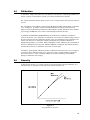
Calibration
6-5
6.6
Linearity
6-5
6.7
Temperature Compensation
6-6
6.8
Level Sensing and Sipper Interference
6-6
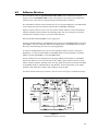
6.9
Software Structure
6-7
7.1
Daily Maintenance
7-1
7.2
Calibration Pumping System Maintenance
7-3
7.3
Sample Chamber Cleaning
7-4
7.4
Membrane Replacement
7-5
7.5
Probe Cleaning
7-6
7.6
Tubing Replacement
7-7
7.7
Sipper Replacement
7-9
7.8
Sipper Ground Cable
7-9
7.9
Fuse Replacement
7-10
7.10 Sipper Pump Seal Replacement
7-11
7.11 Sipper Mechanism Lubrication
7-13
#$%
8.1
Printout Information
8-2
8.2
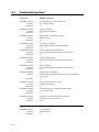
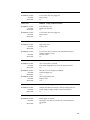
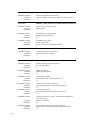
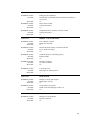
Troubleshooting Chart
8-4
9.1
Communications Protocol
9-1
9.2
Communications Modes
9-5
9.3
Communications Commands
9-6
ii
'( '
) *
A-1
'( + ,%
B-1
'( C-1
'( -
, .
D-1
'( /
. ,0 1
E-1
'( .
2 % F-1
'( 3 4 5 % 2%
'( 6
'( %7 - % -
/ iii
G-1
H-1
I-1
Figure 2.1
Inside Front View of the 2700 SELECT
2-2
Figure 2.2
Back View of the 2700 SELECT
2-4
Figure 2.3
Bottles and Level Sensor Cables
2-5
Figure 2.4
Sample Chamber/Sensors
2-6
Figure 2.5
Enzyme Membrane Installation
2-7
Figure 2.6
Line Voltage Selector
2-8
Figure 2.7
Sipper Adjustment Position
2-10
Figure 3.1
2700 SELECT Software Structure
3-1
Figure 3.2
Sampling Stations
3-4
Figure 3.3
The Test Tube Holder Pivoted Out
3-4
Figure 3.4
The Manual Station
3-6
Figure 5.1
2700 SELECT Software Structure
5-1
Figure 5.2
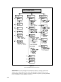
YSI 2700 SELECT Menu Flow Chart
5-2
Figure 5.3
2700 SELECT Major Components
5-17
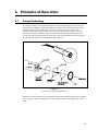
Figure 6.1
Sensor Probe and Enzyme Membrane
6-1
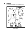
Figure 6.2
2700 SELECT Fluid System
6-3
Figure 6.3
Typical Sensor Response
6-4
Figure 6.4
Aging Membrane Response
6-5
Figure 6.5
2700 SELECT Software Structure
6-7
Figure 7.1
Sample Chamber Illustration
7-5
Figure 7.2
Tubing Connections
7-7
Figure 7.3
Pump Tubing installation
7-8
Figure 7.4
Pump Assembly
7-9
Figure 7.5
Fuse Replacement
7-10
Figure 7.6
Sipper Pump Head Removal
7-11
Figure 7.7
Sipper Pump Seal Replacement
7-12
Figure 7.8
Sipper Pump Plunger Position
7-12
Figure 7.9
Sipper Mechanism Drive Screw and Guide Rods
7-13
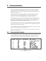
Figure 9.1
RS-232 Signal Description and Direction
9-1
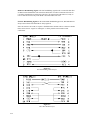
Figure 9.2
Full Handshaking DTE Interface
9-2
Figure 9.3
Three Wire DTE Interface
9-2
Figure 9.4
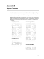
2700 SELECT Data Report Format
9-7
Figure 9.5
Report Format Field Information
9-8
Figure 9.6
RM Command Report Format
9-15
Figure 9.7
RI Command Report Format
9-16
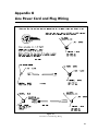
Figure G.1
Line Power Cord and Plug Wiring
G-1
iv
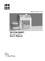
The YSI Model 2700 SELECT Biochemistry Analyzer is a laboratory instrument intended for
use in research, food-processing and bioprocessing applications. THE MODEL 2700 SELECT
IS NOT FOR HUMAN MEDICAL DIAGNOSTIC USE OR FOR HUMAN
PERFORMANCE EVALUATION.
The Model 2700 SELECT offers precision and specificity comparable to more time consuming
and rigorous methods, but with greater speed, convenience and sensitivity. Many of the
conditions which interfere with refractometers, density meters and manual methods are of little
concern when using the Model 2700 SELECT. Measurements are virtually unaffected by
sample color, turbidity, density, viscosity, pH, volatility, specific gravity, temperature, index of
refraction, optical activity, or the presence of proteins or other biochemicals.
The Model 2700 SELECT can be set up to measure a number of different analytes, but
switching between them may entail some time and effort. Configured as a single channel unit,
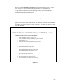
the Model 2700 SELECT provides quick measurements of any one of the following analytes:
•
D-Glucose (Dextrose)
•
L-Lactate
•
Sucrose
•
Lactose
•
Ethanol
•
L-Glutamate
•
Choline
•
L-Glutamine
•
Methanol
•
Galactose*
•
Hydrogen Peroxide*
Configured as a dual channel unit, the Model 2700 SELECT provides quick, simultaneous
measurements of combinations of the following analytes:
•
Dextrose and L-Lactate
•
Dextrose and Sucrose
•
L-Glutamate and L-Glutamine
* YSI does not currently offer calibration standards for these analytes.
1-1
Flexibility is an important feature of the product. Within practical limits a large number of
measurement parameters can be selected to fit your application. In addition, the default
parameters of many system functions can be changed to fit your needs.
Selectable sample size allows you to extend the dynamic range of the analyzer and improves
precision and accuracy. The aspirated sample size can be specified from a minimum of 5
microliters to a maximum of 65 microliters.
The Model 2700 SELECT is equipped with automatic self-calibration. However, within limits,
the frequency of autocalibration can be programmed to meet your needs.
If instrument calibration is desired upon command only, the self-calibration feature can be
disabled and calibration cycles can be initiated manually via the keypad or commanded by the
host computer via the RS-232 interface.
YSI provides a full line of reagents to support the most common chemistries.
YSI offers the Model 2710 Turntable for batch sampling of up to 24 tubes or vials. The 2710
Turntable is controlled by the 2700 SELECT software via a control cable (provided). The
results of batch sampling are displayed and printed by the 2700 SELECT.
YSI offers the Model 2730 Monitoring and Control Accessory for use in applications where
monitoring and control is desired. The Kit contains a peristaltic pump, external sampling
chamber, and tubing for delivering a sample to the 2700 SELECT. Purge time and sampling
interval are selectable, under control of the 2700 SELECT software. Also included in this
accessory are analog outputs representative of analyte concentrations.
The 2700 SELECT has been designed for future additions to allow even greater versatility
related to sample handling and the measurement of additional analytes. Therefore, as
accessories become available or new chemistries are developed you have a basic instrument
upon which to build.
1-2
•
Single and dual chemistry configurations.
•
Minimal sample preparation.
•
Sample aspiration from a variety of tubes.
•
Selectable sample aspiration volume (5 to 65 µL).
•
Sample results in about one minute.
•
Fluid sensing minimizes carry-over.
•
Fluid design washes inside and outside of sipper tube.
•
Programmable automatic calibration.
•
Selectable concentration units, including g/L, mg/L, mmol/L, %(w/v).
•
Liquid crystal display and built-in data printer.
•
RS-232 serial port.
•
Turntable interface circuitry installed.
•
User-accessible service and diagnostic menus.
1-3
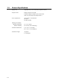
Sample size:
Adjustable from 5 to 65 microliters (aspirated volume)
Response Time:
Sample results in 60 seconds,
Complete sample-to-sample cycle in 90 seconds
(May vary with analyte and sample matrix.)
Power requirement:
110-120 VAC or 220-240 VAC
50-60 Hz
50 Watts nominal
Working environment:
Ambient temperature:
Relative humidity:
1-4
15° to 35° Celsius
10% to 90% (non-condensing)
Instrument dimensions:
10.0 x 14.0 x 14.0 inches
25.4 x 35.6 x 35.6 centimeters
Instrument weight:
25 pounds
11.4 kilograms
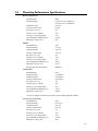
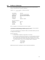
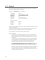
!"#$"
Dextrose (D-Glucose)
YSI Membrane:
Detection Range:
Calibration Point:
Linearity Check Point:
Precision (CV,n=10):
Linearity (0 to Cal Point):
Linearity (Cal to Range Max):
Typical Membrane Working Life:
Membrane O-ring Color:
2365
0-9 g/L at 25 µL sample size,
0-25 g/L at 10 µL sample size
2.50 g/L
9.0 g/L
2%
±2%
±5%
21 days
Red
Ethanol
YSI Membrane:
Detection Range:
Calibration Point:
Linearity Check Point:
Precision (CV,n=10):
Linearity (0 to Cal Point):
Linearity (Cal to Range Max):
Typical Membrane Working Life:
Membrane O-ring Color:
Potential Substrate Interference:
2786
0-3.2 g/L
2.00 g/L
3.20 g/L
2%
±2%
±5%
5 days
Green
Methanol
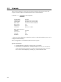
L-Glutamate*
YSI Membrane:
Detection Range:
Calibration Point:
Linearity Check Point:
Precision (CV,n=10):
Linearity (0 to Cal Point):
Linearity (Cal to Range Max):
Typical Membrane Working Life:
Membrane O-ring Color:
2754
0-10 mmol/L
5.00 mmol/L
10.0 mmol/L
2%
±2%
±5%
7 days
Yellow
*User may configure instrument to measure as monosodium glutamate (MSG).
L-Lactate (L-Lactic Acid)
YSI Membrane:
Detection Range:
Calibration Point:
Linearity Check Point:
Precision (CV,n=10):
Linearity (0 to Cal Point):
Linearity (Cal to Range Max):
Typical Membrane Working Life:
Membrane O-ring Color:
2329
0-2.67 g/L
0.50 g/L
2.67 g/L
2%
±2%
±5%
14 days
Gray
1-5
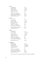
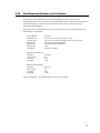
Lactose
YSI Membrane:
Detection Range:
Calibration Point:
Linearity Check Point:
Precision (CV,n=10):
Linearity (0 to Cal Point):
Linearity (Cal to Range Max):
Typical Membrane Working Life:
Membrane O-ring Color:
2702
0-25 g/L
5.00 g/L
25.0 g/L
2%
±2%
±5%
10 days
White
Sucrose
YSI Membrane:
Detection Range:
Calibration Point:
Linearity Check Point:
Precision (CV,n=10):
Linearity (0 to Cal Point):
Linearity (Cal to Range Max):
Typical Membrane Working Life:
Membrane O-ring color:
2703
0-25 g/L
5.00 g/L
25.0 g/L
2%
±2%
±5%
10 days
Blue
Choline
YSI Membrane:
Detection Range:
Calibration Point:
Linearity Check Point:
Precision (CV,n=10):
Linearity (0 to Cal Point):
Linearity (Cal to Range Max):
Typical Membrane Working Life:
Membrane O-ring color:
2771
0-450 mg/L
175 mg/L
450 mg/L
2%
±2%
±5%
7 days
Orange
L-Glutamine*
YSI Membrane:
Detection Range:
Calibration Point:
Linearity Check Point:
Precision (CV,n=5 ):
Linearity (0 to Cal Point):
Linearity (Cal to Range Max):
Typical Membrane Working Life:
Membrane O-ring color:
2735
0-8 mmol/L
5.00 mmol/L
8.00 mmol/L
4%
±4%
±5%
5 days
Magenta
*Specs shown are for simultaneous measurement of glutamine and glutamate.
1-6
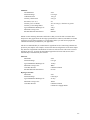
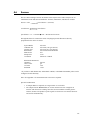
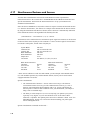
Methanol
YSI Membrane:
Detection Range:
Calibration Point:
Linearity Check Point:
Precision (CV,n=10 ):
Linearity (0 to Cal Point):
Linearity (Cal to Range Max):
Typical Membrane Working Life:
Membrane O-ring color:
Potential Substrate Interference:
2725
0-2.50 g/L
1.00 g/L
2.50 g/L
2%
±2% or 0.02 g/L, whichever is greater
±5%
5 days
Black
Ethanol
NOTE: For the following chemistries YSI believes that you will be able to measure these
analytes for many applications in the ranges specified below. However, YSI makes no claims
with respect to precision or linearity. For each analyte below you will need to prepare the
calibrator and linearity standards for your application.
YSI also recommends that you confirm that no significant levels of interfering substrates are
present in your samples. For example, we know that lactose and galactose in the same sample
may interfere if significant concentrations of both exist. Also dextrose will read at a sucrose
membrane, however, by using the dual channel approach to dextrose and sucrose, this is
automatically accounted for by the software.
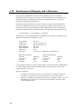
Galactose
Membrane:
Detection Range:
Typical Membrane Working Life:
Membrane O-ring Color:
User Must Provide:
Potential Substrate Interference:
Hydrogen Peroxide
Membrane:
Detection Range:
Typical Membrane Working Life:
Membrane O-ring Color:
User Must Provide:
2702
0-25 g/L
10 days
White
Calibrator solution
Lactose
2701
0-600 mg/L
21 days
Yellow
Calibrator solution
Catalase-free Supply Buffer
1-7
%
&'!(
If your instrument is configured for single channel chemistry, this instruction manual contains
more information than you require, but the measurement technology, and the principles and
techniques of operation remain the same.
This manual is organized in such a way as to give you the quickest possible start in operating
the instrument. However, it cannot be stressed too strongly that informed and safe operation is
more than just a matter of knowing which buttons to push. An understanding of the principles
of operation and potential chemical interferences is necessary for the wisest interpretation of
results. Thorough precautions regarding the handling of biological samples are also essential
for the safety of operators.
The early parts of this manual will teach you how to get the instrument running. Additional
topics are included to help you understand the science it employs, how to use it most effectively
and safely, and how to keep it operating correctly.
1-8
We recommend that your dealer representative or YSI regional representative assist with initial
setup and orientation. YSI warranty and product performance claims, however, are not
dependent upon installation by factory or dealer personnel.
Remove the instrument from the shipping container. Be careful not to discard any parts or
supplies. Check off all items on the packing list and inspect all assemblies and components for
damage. In the event of damaged or missing parts, contact YSI Customer Service or your
Dealer Representative immediately.
Note that reagents for the 2700 SELECT Analyzer are not packaged in the same carton as the
instrument. These materials must be ordered separately as starter supplies and will arrive in a
separate package.
DO NOT PLUG THE INSTRUMENT IN AT THIS TIME. You should apply power only
when directed to do so in the setup instructions.
If you ordered the 2700 SELECT with the 2710 Turntable, first set up the 2700 SELECT. Once
the 2700 SELECT is operating properly, refer to the YSI 2710 Turntable Operations Manual.
Notes On Safety (Electrical precautions)
1.
BEFORE connecting the power cord, check the line voltage selector and confirm that the
selected voltage matches the local power supply (Section 2.5).
2.
Use ONLY the line power cord supplied with the instrument. Connect the plug to a
matching three-pronged wall receptacle.
3.
Use ONLY fuses of the type supplied (Section 7.9). Replacement power cords and fuses
can be obtained from YSI, or your Dealer Representative (Appendix F, G).
4.
Do NOT use an extension cord without protective grounding.
5.
Do NOT remove rear cover. There are no user serviceable parts inside.
6.
Repairs are to be performed only by trained and approved personnel.
7.
This instrument must be connected to a protectively grounded (earthed) outlet.
8.
The following notices are provided in compliance with IEC1010 Part 1 1990.
8.1 Fuses F1-F7 on the main circuit board are type: Subminiature (F) to UL 198G Standard.
Rating: F1-F5, 1A; F6-F7, 2A. These fuses are NOT operator replaceable.
8.2 See Appendix G for mains plug wiring and fusing instructions.
9.
If the equipment is used in a manner not specified by YSI, the protection provided by the
equipment may be impaired.
WARNING: For auxiliary connection, refer to the YSI 2710 Turntable Operation Manual or the
YSI 2730 Monitor and Control Accessory User’s Manual. Use with the YSI 2710
Turntable or YSI 2730 Monitor/Control Accessory only.
WARNING: For remote connection, refer to section 9. Communications. Equipment should be
EN 61010 or EN 60950 approved only.
10. The mains (power) switch is for functional purposes ONLY. To disconnect the instrument
from the mains supply, unplug the mains power cord from the back of the instrument.
2-1
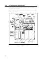
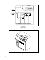
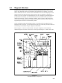
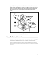
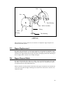
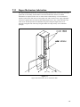
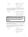
Referring to Figure 2.1 and 2.2, read through the following descriptions and familiarize
yourself with the major components.
NOTE: In maintenance kits, service manuals and part lists the "Sipper" may be referred to as
the Sipper Needle or Sipper Tube.
Figure 2.1
Inside Front View of the 2700 SELECT
2-2
The Buffer Pump draws buffer from its bottle, pumps it through the Sipper Pump body and the
Sipper, and flushes the Sample Chamber.
The Calibrator Pump draws the appropriate standard solution from the Calibrator Bottle and
fills the Calibrator Well in the Sample Chamber.
The Sipper Pump retracts its piston to draw in standard from the Calibrator Well or sample
from a tube or container. It extends its piston to dispense standard or sample into the Sample
Chamber.
The Sipper Arm and Sipper Assembly is raised or lowered by one motor, and moved
horizontally to its various positions by another motor. The positions are: Calibrator Well
(Station #1), Sample Chamber ("home"), Test Tube Holder Station (Station #2), Manual Station
(Station #3), Turntable Station (Station #4) and Monitor Station (Station #5). The Sipper
capacitively senses fluid to control immersion depth and detect errors.
The Stir Bar is a plastic encapsulated magnet. It is activated by a motor housed below the
Sample Chamber. It provides thorough mixing inside the chamber.
The Buffer, Waste and Calibrator Bottles are visible through the front door window for easy
monitoring of fluid levels. A stainless steel shaft projecting into each bottle terminates with a
connector on the lid, providing a signal used to halt operations when the Buffer or Calibrator
Bottles are empty, or when the Waste bottle is full.
The Sample Chamber is made of clear acrylic plastic. White and black holders for the sensor
probes are screwed to either side. The immobilized enzyme membranes on the sensor probes
are mounted on O-rings which act as fluid seals on each side of the Sample Chamber. A
reference or auxiliary electrode is housed in the temperature probe and positioned at the back of
the Sample Chamber. It is held in place by a retainer that threads directly into the Sample
Block. A small black O-ring slips over the temperature probe/electrode to provide the seal. The
Calibrator Well is located behind and to the right of the Sample Chamber entry port.
The Test Tube Holder pivots out to allow insertion or removal of several common size test
tubes.
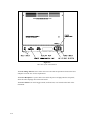
The Display is a 2 line by 40 character liquid crystal display.
The Printer provides a hard copy record of sample results, calibration currents and errors. It
uses 2 1/4 inch (56 mm) wide thermal paper.
The Keypad is a 20 key membrane switch. It has 0-9 numeric keys, SPACE and BACK keys
and 8 function keys.
The Reset Switch is located on the back of the instrument. It is used to hard reset the operating
system.
The Remote Communication Port is an RS-232 serial port. It is used to interface with host
computers or other laboratory instruments.
The Auxiliary Port is an interface connector for use with accessories like the YSI 2710
Turntable.
2-3
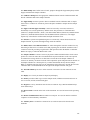
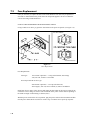
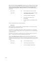
Figure 2.2
Back View of the 2700 SELECT
The Line Voltage Selector selects either 110-120 or 220-240 volt operation. It houses the fuses
and pulls out of the case for fuse replacement.
The Power Receptacle is a power inlet. One end of the power cord plugs into this receptacle,
while the other end plugs into an electrical outlet.
The Power Switch is an on/off toggle switch (0-off and I-on). It is located on the back of the
instrument.
2-4
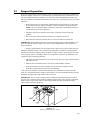
Prepare the supply buffer and fill the buffer bottle. Powdered buffer concentrate is included in
the starter supplies. YSI 2357 is recommended for use with all YSI Enzyme Membranes except
YSI 2702 Galactose Oxidase membranes (use YSI 2705), YSI 2786 Ethanol Membranes (use
YSI 2787) and YSI 2725 Methanol Membranes (use YSI 1579). All YSI buffers may be ordered
separately.
» Place about 500 mL of reagent water (distilled and/or deionized) into a one liter flask,
or other clean container. Add two packages of YSI 2357 Buffer Concentrate and stir.
NOTE: YSI 1579 Carbonate Buffer Concentrate (used with 2725 membranes) must be
reconstituted as instructed on the bottle.
» Add more reagent water until the total volume of solution is between 900 and
1000 mL.
» Stir as necessary, until the buffer chemicals have completely dissolved.
» Disconnect the electrical lead from the level sensor and remove the bottle lid.
IMPORTANT: When adding fresh buffer to the Buffer Supply Bottle or when installing a new
bottle of Calibrator Solution, make every effort to avoid contamination of the lid and level
sensor assemblies.
» Pour the prepared buffer into the supply bottle, replace the lid, and reconnect the lead.
Install the calibrator solution. One or more of the following YSI calibration standards will be
provided in your starter supplies, YSI 2776 (Dextrose and L-Lactate), YSI 2780 (Sucrose), YSI
2783 (Lactose), YSI 2772 (Choline), YSI 2755 (L-Glutamate), YSI 2736* (L-Glutamine). YSI
calibrators may be purchased separately.
» Unplug the electrical lead from the level sensor in the lid of the empty calibrator bottle
and remove the lid.
» Mark the date of installation on the new bottle of YSI calibrator solution.
» Screw the lid and level sensor assembly onto the new bottle and place it in the
instrument compartment. Reconnect the electrical lead.
* The YSI 2736 Glutamine Calibration Standard must be reconstituted as instructed on the
bottle. It is recommended that a sample be poured into a test tube and installed at station #2 for
calibration. Refrigerate the bulk solution when not in use.
IMPORTANT: The level sensor cables should not touch the instrument housing. It is best to
keep the cable connector on the bottle lid pointed toward the front. False messages concerning
fluid levels may result if the bottles are not installed inside the fluid compartment and the
cables routed as shown in Figure 2.3.
Figure 2.3
Bottles and Level Sensor Cables
2-5
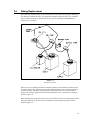
!
"#$
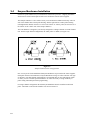
Each active probe installed in your instrument is fitted with a protective "shipping membrane"
which must be removed and replaced with a new membrane from the starter supplies.
The Sample Chamber is color coded to assist you in membrane installation and setup. The left
side of the chamber has a black probe housing, and the right side has a white probe housing.
(Throughout this manual, whenever we refer to the "black" or "white" probe, the reference is to
the "black" or the "white" side of the sample chamber.)
The 2700 SELECT is shipped to you already configured as a Single Channel or a Dual Channel
unit. For the single channel configuration, the white probe is a blank (see Figure 2.4).
Figure 2.4
Sample Chamber/Sensor Configurations
One or more packs of YSI Immobilized Enzyme Membranes is provided in the starter supplies.
Each pack contains four membranes. Enzyme Membrane O-rings are color-coded for each type
of chemistry. For dual channel configurations it is important that you note which probe, black
or white, you use to install specific membranes. It will be necessary to assign chemistry to
probe during instrument parameter programming.
For single channel configuration the YSI Enzyme Membrane must be installed on the black
probe. The blank is sealed in the chamber. You need not remove it.
2-6
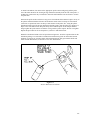
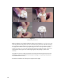
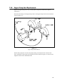
To install a membrane, first unscrew the appropriate probe retainer and gently pull the probe
out of the block. Remove the existing O-ring membrane assembly from the end of the probe. A
toothpick or pointed tool may be needed to unseat the old membrane. Be careful not to scratch
the probe face.
Examine the probe surface and remove any pieces of membrane that remained. Open a cavity of
the plastic membrane holder and rinse the membrane inside with a few drops of salt solution
(YSI 2392 or equivalent). Place one drop of salt solution on the probe face. Using the plastic
membrane holder, press the O-ring membrane assembly gently onto the probe face (Figure 2.5).
Wipe excess salt solution from the probe body, then return the probe to the sample chamber.
Finger tighten the probe retainer so that the O-ring seals the probe in place. Do not overtighten.
Repeat this procedure for the second probe if you have a dual channel unit.
Return the membrane holder to the foil pouch and refrigerate it. Note the expiration date on the
membrane package. It is advisable to maintain an instrument log book in which dates and lot
numbers of reagents are recorded, along with information from daily operational checks and
other relevant information (see Section 3.3 for more information).
Figure 2.5
Enzyme Membrane Installation
2-7
%
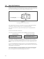
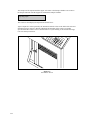
& BEFORE YOU PLUG IN THE POWER CORD, inspect the Line voltage selector on the back of
the instrument (See Figure 2.6). Be certain the correct voltage is selected. The arrowhead on the
power selector must be pointing to the small rectangle on the housing, as shown.
Figure 2.6
Line Voltage Selector (110-120V Position)
If the voltage selection is incorrect, review Section 7.9 for correct voltage selection and fuse
requirements or contact YSI Customer Service or your Dealer Representative.
If the voltage selection is correct, plug in the unit using the power cord packaged with the
instrument.
Set the power switch to ON. (0-off and I-on).
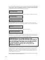
Correct Power-up operation is confirmed by observing either of the following displays:
Main Menu Display
Please select instrument mode:
[RUN] [STANDBY] [MENU]
Default Parameters Display
***Warning: instrument parameters have
been set to default. Hit key to set up.
The instrument will normally arrive with parameters, including date and time, set from the
factory. However, if the backup rechargeable batteries have run down, you will see the Default
Parameters message. This message will also appear if you ever need to change batteries in the
future.
If you see the Default Parameter message, press any key to access the Setup Menu, then press
[MENU] to return to Main Menu as displayed above. Specific instructions to set date, time, and
other parameters are described below.
If the Main Menu Display does not appear immediately or after you have tried the procedures
above, reset the instrument by pressing the reset switch on the back panel or by turning the
power off, waiting about 20 seconds, then turning the power back on.
2-8
'
(
Since it may take an hour or more to initially stabilize the probes when setting up for the first
time, now is a good time to prime the fluid system. You have already reconstituted the
appropriate buffer and transferred it to the Buffer Bottle. You have also installed the appropriate
calibrator solution and installed the appropriate Enzyme Membrane(s) in the Sample Chamber.
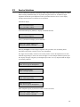
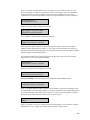
With the Main Menu displayed (see below), press [MENU], then press [1] for Service.
Please select instrument mode
[RUN] [STANDBY] [MENU]
Select instrument function
1-Service 2-Setup 3-Diagnostic
Select service: 1-Sipper 2-Buffer 3-Cal
4-Stir speed 5-Monitor 6-Turntable
You are now ready to align the Sipper, prime the fluid pumps and adjust the stirring. Since the
adjustments were made prior to shipment, this procedure will likely be just a check.
IMPORTANT: The front door must remain open to carry out this procedure.
)*+,-..
&..
/.&...
/0.$
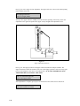
To make certain the Sipper Arm and attached Sipper are correctly aligned, follow the
instructions below.
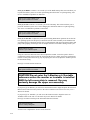
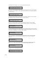
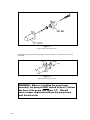
Press [1] for Sipper. The Sipper Arm will move to the "home" position. The tip of the Sipper
should be centered over the large hole on the top of the Sample Chamber (see Figure 2.7). If
necessary, loosen the adjustment screw and position the Sipper. The adjustment tool (hex key)
is included in the preventive maintenance kit that is packed with your instrument. Retighten the
adjustment screw.
Adjust sipper then select
0-Exit 1-Lower sipper for fine alignment
2-9
Press [1] for Lower sipper for fine alignment. The Sipper will move closer to the small opening
in the stainless steel cone.
Fine align sipper then select
0-Exit 1-Test sipper position
The tip of the Sipper should be exactly centered above this opening. If necessary, loosen the
adjustment screw again and position the Sipper exactly. Retighten the adjustment screw.
Figure 2.7
Sipper Adjustment Position
Press [1] for Test Sipper position. The Sipper will descend into the Sample Chamber. The
Sipper should not contact the stainless steel cone. If the Sipper position is still not exactly right,
press [1] and readjust it once more, as described above. IT IS VERY IMPORTANT THAT
THE SIPPER BE ACCURATELY ADJUSTED.
Select 1 to restart check sipper cycle
0-Exit 1-Home sipper position
After adjustment is complete, press [0] to exit and return to the Select Service menu level.
Select service: 1-Sipper 2-Buffer 3-Cal
4-Stir speed 5-Monitor 6-Turntable
2-10
Press [2] for Buffer. The Sipper will enter the Sample Chamber and the Buffer Pump will begin
to prime the fluid system with buffer solution. The fluid system is completely primed when
buffer flows from the steel cone at the top of the sample chamber. Press [2] again, if necessary.
Select service: 1-Sipper 2-Buffer 3-Cal
4-Stir speed 5-Monitor 6-Turntable
Press [3] for Cal. The Calibrator Pump will begin to pump calibrator through the calibrator line
into the Calibrator Well in the Sample Chamber. If necessary, press [3] again until calibrator
flows out of the tube in the cal well.
Select service: 1-Sipper 2-Buffer 3-Cal
4-Stir speed 5-Monitor 6-Turntable
Press [4] for Stir Speed. The menu message shown below will appear. The stir bar has two
operating speeds; normal speed, at which the stir bar rotates smoothly in the chamber, and
accelerated speed, at which the stir bar loses synchronization with the motor housed below, and
jumps. This jumping action helps clear the Sample Chamber of air bubbles during a flush cycle.
Adjust until stir bar jumps
1-Increase speed 2-Decrease speed
Adjust the speed until the stir bar jumps or is set to maximum. Next press [0] to return to the
Select service menu level.
Select service: 1-Sipper 2-Buffer 3-Cal
4-Stir speed 5-Monitor 6-Turntable
When all adjustments are complete, press [MENU] to return to Main Menu level.
Please select instrument mode
[RUN] [STANDBY] [MENU]
1
Open the paper cover on top of the instrument. Insert the loose end of the paper into the slot on
the printer. The outermost side of the paper on the roll should be facing down. Press [PAPER]
to advance the paper through the printer.
2-11
2
The 2700 SELECT setup is menu driven. Once set up, the system parameters are maintained in
memory. In the event of power loss, the 2700 SELECT has a battery backup to maintain its
memory. Follow the procedure below to program your instrument parameters.
IMPORTANT: You move through the 2700 SELECT menus by selecting options on the
display. Refer to Figure 5.1 for an overview of the menu structure. You can press the MENU
key to get back to the Main Menu, and the 0 key to back up to the previous display. However, it
may be necessary to confirm a response by pressing [ENTER] before continuing to use the
MENU or 0 keys.
The Main Menu display is shown below.
Please select instrument mode
[RUN] [STANDBY] [MENU]
From the Main Menu, press [MENU]. The following display will appear:
Select instrument function
1-Service 2-Setup 3-Diagnostic
Press [2] for Setup. The instrument now displays 6 categories as shown below.
Select setup: 1-General 2-MeasParameter
3-RunMode 4-Report 5-PrntSetup 6-Default
During normal operation you will seldom need to enter the Menu Mode, but it is important to
familiarize yourself with the menu locations of the various parameters over which you have
control. See Section 5.3 for complete details of menu options.
Press [5] for PrntSetup. The data printer will print the instrument setup parameters. This will
take less than a minute and use approximately 8 inches (20 centimeters) of printer paper. The
hard copy of the current parameters setup should help you as you work through this menu.
Each category of the Setup Menu is briefly described below. For now, study the Setup
categories. A step-by-step set of instructions that leads you through an example setup will
follow.
Press [1] for General. The display will read:
General setup: 1-Date/Time 2-Contrast
3-RS-232 4-Radix 5-Serial# 6-LevelSensor
1-General. In this menu you may confirm or change the date, set date format, adjust the display
contrast, define communication parameters, select the radix to express decimal numbers,
confirm or enter the instrument serial number and select whether to deactivate the bottle level
sensor system.
2-12
Press [0] to back up, then press [2] for MeasParameter. The display will read:
Measurement parameter setup
1-SampleSize 2-CalMethod 3-Black 4-White
2-MeasParameter. "MeasParameter" is an abbreviation for measurement parameters. From this
menu you may select the sample size (5-65 microliters). You may also specify the locations
(station #) of calibrator solutions, which is especially useful in certain dual chemistry
applications. From this menu, you will also confirm or change specific parameters dealing with
the black probe (single channel unit) or black and white probes (dual channel unit). These
parameters include chemistry assignment, calibration value, units of concentration, and time to
endpoint of reaction.
NOTE: YSI has assigned default values for each of these parameters, but provides the
flexibility for the user to change values to optimize a particular application. DURING
INITIAL SETUP, YSI RECOMMENDS THAT YOU USE THE DEFAULT SETTINGS
FOR THE CHEMISTRIES YOU CHOOSE.
Press [0] to back up, then press [3] for RunMode. The display will read:
RUN mode setup: 1-SampleProtocol
2-AutoStandby 3-AutoCal 4-Monitor
3-RunMode. In this menu, you select parameters related to sampling protocol, set parameters
that control automatic switching to standby mode and select parameters that will trigger autocalibrations. In Sample Protocol, you can select the sample station (position), activate replicate
sampling and sample identification prompts, set the position to which the Sipper descends when
sampling at the Manual Station, and set turntable parameters, if appropriate.
Press [0] to back up, then press [4] for Report. The display will read:
Select sample report format: Brief
1-None 2-Brief 3-Detail
4-Report. In this menu you select the level of detail you desire for the printed sample and
calibration reports. You probably would reserve detail reporting for troubleshooting a suspected
problem. Press [ENTER] to confirm brief sample report format.
Select cal report format: Brief
1-None 2-Brief 3-Detail
Press [ENTER] again to confirm brief cal report format.
Press [5] for PrntSetup. The display will read:
Printing instrument setup... Please wait
5-PrntSetup. This is an abbreviation for "print setup". Once you have selected your setup
parameters, you may record these choices by printing them on the data printer. You have
already been instructed to print this to learn about the 2700 SELECT menu.
2-13
Press [6] for Default. The display will read:
Reset all system parameters? No
1-No 2-Yes
6-Default. In this menu you have the option to reset all default parameters, i.e., those set in the
software to serve your needs for all standard applications. Using this command also requires
that you reset date, time, and all other general parameters. Press [ENTER] to confirm "No" and
return to Select Setup menu.
Now press [MENU] to return to Main Menu display:
Please select instrument mode
[RUN] [STANDBY] [MENU]
2-14
3
"4,
5$5
Next we will show a step-by-step instrument programming procedure to illustrate the flexibility
you have with the 2700 SELECT. For illustration purposes, we will demonstrate initial setup for
simultaneous determination of dextrose and L-lactate on a dual channel 2700 SELECT.
NOTE: If you have a single channel unit, this example has more information than you need.
However, it will cover all pertinent information to set up a single channel unit.
This is a straight-forward setup utilizing one calibration solution to perform simultaneous
chemistries. Follow along by pressing keys on your 2700 SELECT. This exercise will be a good
learning tool. After completing the exercise, you will be directed to parts of the manual related
to your specific chemistry interests.
EXAMPLE: Set up the YSI 2700 SELECT to measure D-glucose (dextrose) and L-lactate,
simultaneously. Let us assume you have installed a YSI 2329 Lactate Membrane on the black
probe and a YSI 2365 Glucose Membrane on the white probe. YSI 2357 buffer has been
reconstituted and poured into the Buffer Bottle and YSI 2776 Standard (2.50 g/L dextrose and
0.50 g/L L-lactate) has been installed into the Calibrator Bottle position. The instrument has
been powered and the printer paper installed.
Let us also assume that you have your sample in a test tube and want to program the unit to run
the sample three times in succession (triplicate). You would also like to identify the sample by
an identification number to be printed with the result. To conserve printer paper you would like
the "brief" report version of sample and calibration results. As recommended for Initial Setup,
you will use all default measurement parameters.
In Section 2.8 you became familiar with the 6 categories in the Setup Menu and you were last
instructed to press MENU to display Main Menu. This is the level in the menu where we want
to start. If you have entered Run Mode or Standby Mode, see page 3-1 for instructions to exit
either mode.
At this time you may want to refer to Figure 5.2, Menu Flow Chart.
Main Menu:
Please select instrument mode
[RUN] [STANDBY] [MENU]
Press [MENU].
Select instrument function
1-Service 2-Setup 3-Diagnostic
Press [2] for Setup.
Select setup: 1-General 2-MeasParameter
3-RunMode 4-Report 5-PrntSetup 6-Default
2-15
Press [1] for General.
General setup: 1-Date/Time 2-Contrast
3-RS232 4-Radix 5-Serial# 6-LevelSensor
Press [1] for Date/Time. Use the number keys to change entries. Press [ENTER] to confirm
each entry.
Enter date and time as required
Year> 98
Enter year.
Enter date and time as required
Month> 2
Enter month.
Enter date and time as required
Date> 14
Enter day.
Enter date and time as required
Hour> 17
Enter hour.
Enter date and time as required
Minute> 22
Enter minute.
Select date format: MM/DD/YY
1-MM/DD/YY 2-DD/MM/YY
Select and/or confirm the format you desire for printed dates: (month/day/year);
(day/month/year).
With the entry of the date format you will return to the previous menu level, General setup.
General setup: 1-Date/Time 2-Contrast
3-RS232 4-Radix 5-Serial# 6-LevelSensor
Press [2] for Contrast.
Adjust the display contrast
1-Raise contrast 2-Lower contrast
2-16
Use the appropriate number key to adjust the LC display contrast for comfortable viewing.
When finished, press [0] to return to General setup.
General setup: 1-Date/Time 2-Contrast
3-RS232 4-Radix 5-Serial# 6-LevelSensor
Press [3] for RS-232.
RS-232 setup 1-Baud 2-Data 3-Parity
4-Stop 5-Handshake 6-Configuration
This menu is used to set communication parameters. Press [0] to return to General setup or
explore these parameters, remembering to press [ENTER] to move through each choice and
back to RS-232 setup.
General setup: 1-Date/Time 2-Contrast
3-RS232 4-Radix 5-Serial# 6-LevelSensor
Press [4] for Radix.
Select radix mark: "."
1-" . " 2-" , "
In some parts of the world a "," is preferred to express decimal numbers. Example, 2.00 = 2,00.
Confirm your choice by pressing [ENTER] to return to the General setup.
General setup: 1-Date/Time 2-Contrast
3-RS232 4-Radix 5-Serial# 6-LevelSensor
Press [5] for Serial#.
Enter instrument serial number
98 12345
The serial # of your instrument is recorded on the serial plate, lower rear of case. You will find
it helpful to record this number in memory. It will be printed in the detailed report format and
will be very useful if technical assistance or repair is required. Since YSI uses alpha-characters
in the serial #, we recommend that you use a space for these characters. Example: 98B12345AB
can be entered as 98 12345.
You will find the number in memory since it is entered prior to shipment and should be
preserved by battery backup. Press [ENTER] to confirm and return to General setup.
General setup: 1-Date/Time 2-Contrast
3-RS232 4-Radix 5-Serial# 6-LevelSensor
Press [6] for LevelSensor.
Activate bottle level sensors? Yes
1-No 2-Yes
2-17
Choosing Yes maintains level sensing in the Buffer, Calibrator, and Waste bottles. Press
[ENTER] to return to General setup.
General setup: 1-Date/Time 2-Contrast
3-RS232 4-Radix 5-Serial# 6-LevelSensor
You have now completed General setup. Press [0] to return to Select setup menu level.
Select setup: 1-General 2-MeasParameter
3-RunMode 4-Report 5-PrntSetup 6-Default
Press [2] for MeasParameter.
Measurement parameter setup
1-SampleSize 2-CalMethod 3-Black 4-White
Press [1] for SampleSize.
Enter sample size in microliter
> 25
The default setting is 25 microliter (µL). The options range from 5 to 65 µL. If you enter a
number outside of this range, the display will show you the limits. Press [ENTER] to confirm
25 µL and return to the Measurement parameter setup menu level.
Measurement parameter setup
1-SampleSize 2-CalMethod 3-Black 4-White
Press [2] for CalMethod.
Select calibration method: One Station
1-One Station 2-Two Stations
Press [ENTER] to confirm One Station, since both dextrose and L-lactate are in one calibrator
bottle and reside in one location.
Enter Cal Station #
> 1
Press [ENTER] to confirm that the calibrator solution (YSI 2776) is installed at Station #1 (Cal
Well of the Sample Chamber). The display now returns to the Measurement parameter setup
menu level.
Measurement parameter setup
1-SampleSize 2-CalMethod 3-Black 4-White
2-18
Press [3] for Black. At this level you will choose chemistry and other black probe measurement
parameters.
Select BLACK chemistry: L-Lactate
0-Backup 1-Next chemistry [ENTER]-Accept
Press [1] for Next chemistry. Use this key to scroll through the choices in the menu. For our
example, choose L-Lactate, then press [ENTER] to confirm and move on to the next parameter.
Select BLACK unit of measurement: g/L
1-mmol/L 2-mg/L (ppm) 3-g/L 4-% (w/v)
Press [1] for mmol/L. This changes the ‘g/L’ default setting.
Select BLACK unit of measurement: mmol/L
1-mmol/L 2-mg/L (ppm) 3-g/L 4-% (w/v)
Press [ENTER] to confirm and move to the next parameter.
Enter Black calibration value in mmol/L
> 05.62
The value you observe (5.62 mmol/L) is equivalent to 0.50 g/L, the concentration stated on the
YSI 2776 calibrator label.
NOTE: If you are using the default values and you choose a concentration unit other than g/L,
the value automatically changes. That is, 0.50 g/L becomes 5.62 mmol/L or 500 mg/L. When
non-standard calibration values are used, however, the appropriate numbers must be entered
whenever the measurement unit is changed.
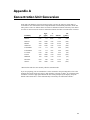
ALWAYS VERIFY THAT THE CORRECT CALIBRATION VALUE IS ENTERED! Use
the information in Appendix A to make the necessary unit conversions for calibration entry.
Press [ENTER] to confirm and move to the next parameter.
Enter BLACK end point in seconds
> 30
Press [ENTER] to confirm the 30 second endpoint parameter. The options range from 15 to 125
seconds. The display now shows the Measurement parameter setup menu level.
Measurement parameter setup
1-SampleSize 2-CalMethod 3-Black 4-White
Press [4] for White. Now set the same parameters for the White probe that you set for the Black
probe.
Select WHITE chemistry: Dextrose
0-Backup 1-Next chemistry [ENTER]-Accept
2-19
Press [ENTER] to confirm Dextrose.
Select WHITE unit of measurement: g/L
1-mmol/L 2-mg/L (ppm) 3-g/L 4-% (w/v)
Press the appropriate number to change the default setting, if necessary.
When the desired unit of measurement is selected, press [ENTER] to confirm and move to the
next parameter.
Enter White calibration value in g/L
> 02.50
ALWAYS VERIFY THAT THE CORRECT CALIBRATION VALUE IS ENTERED! Use
the information in Appendix A to make the necessary unit conversions for calibration entry.
Press [ENTER]to confirm and move to the next parameter.
Enter White end point in seconds
> 30
Press [ENTER]to confirm the 30 second endpoint parameter.
Measurement parameter setup
1-SampleSize 2-CalMethod 3-Black 4-White
Press [0] to return to the Select setup level.
Select setup: 1-General 2-MeasParameter
3-RunMode 4-Report 5-PrntSetup 6-Default
Press [3] for RunMode.
RUN mode setup: 1-SampleProtocol
2-AutoStandby 3-AutoCal 4-Monitor
Press [1] for SampleProtocol.
SamplingProtocol setup: 1-SipperHeight
2-Replicates 3-ID 4-Station# 5-Turntable
Press [1] for SipperHeight.
Select manual sipper height: Medium
1-Low 2-Medium 3-High
This specifies to what vertical position the Sipper descends when sampling at the Manual
Station. For example, with long test tubes and the fluid level near the bottom of the test tube,
use "Low" setting. For now choose Medium level, then press [ENTER] to confirm and return to
Sampling protocol setup.
2-20
SamplingProtocol setup: 1-SipperHeight
2-Replicates 3-ID 4-Station# 5-Turntable
Press [2] for Replicates.
Prompt replicate cycle? No
1-No 2-Yes
Since our example setup requests triplicate analysis of the sample, we must activate replicates.
Press [2] for Yes.
Prompt replicate cycle? Yes
1-No 2-Yes
Press [ENTER] to confirm and return to Sampling protocol setup.
SamplingProtocol setup: 1-SipperHeight
2-Replicates 3-ID 4-Station# 5-Turntable
Press [3] for ID.
Prompt sample ID? No
1-No 2-Yes
Again, our example setup requests that we use sample identification. Press [2] for Yes.
Prompt sample ID? Yes
1-No 2-Yes
Press [ENTER] to confirm and return to Sampling protocol setup.
SamplingProtocol setup: 1-SipperHeight
2-Replicates 3-ID 4-Station# 5-Turntable
Press [4] for Station#.
Enter Sample Station #
>2
The default station is Station #2 which is where our test tube will be held. Press [ENTER] to
confirm and return to Sampling protocol setup.
SamplingProtocol setup: 1-SipperHeight
2-Replicates 3-ID 4-Station# 5-Turntable
Press [0] to return to Run mode setup.
RUN mode setup: 1-SampleProtocol
2-AutoStandby 3-AutoCal 4-Monitor
2-21
Press [2] for AutoStandby.
Enter autostandby time in hour
0 to disable > 2
This entry defines the number of hours the unit will continue to update calibration and be ready
to sample. The default setting is "2". Note that you would press [0], then [ENTER] to disable
autostandby which maintains the unit in a "sample ready" mode indefinitely. For now, press
[ENTER] to confirm two hour autostandby and return to the Run mode setup.
RUN mode setup: 1-SampleProtocol
2-AutoStandby 3-AutoCal 4-Monitor
Press [3] for AutoCal.
Autocal setup: 1-Temperature 2-Time
3-Sample 4-Cal shift 5-Sample error
Each parameter in this menu level can be used to alter the conditions which trigger
autocalibrations. For now, simply explore each menu parameter. Access each parameter by
pressing the number. Press [ENTER] to confirm the default setting and return to the Autocal
setup. See Section 5.3 for more information.
)*+,).$
.../$.
06
$/
..7
Autocal setup: 1-Temperature 2-Time
3-Sample 4-Cal shift 5-Sample error
When you have completed this level, press [0] to return to Run mode setup.
RUN mode setup: 1-SampleProtocol
2-AutoStandby 3-AutoCal 4-Monitor
Press [0] again to return to Select setup.
Select setup: 1-General 2-MeasParameter
3-RunMode 4-Report 5-PrntSetup 6-Default
2-22
Press [4] for Report.
Select sample report format: Brief
1-None 2-Brief 3-Detail
The default setting is "brief" report. Press [ENTER] to choose brief Sample report, then press
[ENTER] again to choose brief Cal report. See Appendix D for example printouts of each type
of report.
Select cal report format: Brief
1-None 2-Brief 3-Detail
The Select setup menu is again displayed.
Select setup: 1-General 2-MeasParameter
3-RunMode 4-Report 5-PrntSetup 6-Default
Press [5] for PrntSetup.
Printing instrument setup... Please wait
The instrument will print the setup information. The information is an itemized list of the key
parameters that you have entered into memory for running the 2700 SELECT. See Appendix C
for an example of this report.
When finished, the display again shows the Select setup menu.
Select setup: 1-General 2-MeasParameter
3-RunMode 4-Report 5-PrntSetup 6-Default
Press [6] for Default.
Reset all system parameters? No
1-No 2-Yes
This menu allows you to reset all system parameters to the default settings, that is, those that
would appear if you were to unpower the instrument (including backup battery power). Do not
select 1-Yes now. Instead, press [ENTER] to confirm "No" to resetting system parameters. The
instrument will return to the Select setup menu.
Select setup: 1-General 2-MeasParameter
3-RunMode 4-Report 5-PrntSetup 6-Default
YOU HAVE NOW COMPLETED THE INITIAL SETUP EXAMPLE.
As you learn more about the 2700 SELECT you will gain greater familiarity with the menu
system. If you would like to revisit levels of the Select setup menu, press the appropriate
number(s). If not, press [0] to return to Select instrument function.
2-23
Select instrument function
1-Service 2-Setup 3-Diagnostic
Now press [0] again to return to Main menu.
Please select instrument mode
[RUN] [STANDBY] [MENU]
Now refer to Section 4 to learn about the recommended system parameters for your particular
chemistry application. Next use this information to setup the 2700 SELECT as we have
demonstrated above.
HINT: Use the Print Setup option to confirm that you have correctly setup your instrument.
Remember, "PrntSetup" can be accessed from Main Menu by pressing [MENU], then [2] for
Setup and then [5] for PrntSetup. Again, refer to Figure 5.2, Menu Flow Chart for an overview.
2-24
8
$9.
You were previously instructed to prime the fluid system. Since then, you have been learning
about the menu selections. Now it is time to check the probe baseline current to determine if the
installed enzyme membrane sensor(s) and probe(s) have equilibrated and are stable enough to
initiate calibration.
From the previous instructions your instrument should be displaying Main Menu.
Please select instrument mode
[RUN] [STANDBY] [MENU]
If your instrument display shows another message, press [MENU] on the keypad. The
instrument should display the message above. If you inadvertently entered the Run Mode or
Standby Mode, you will need to exit to return to the Main Menu. See instructions in Section 5.1
regarding entering and exiting these modes.
Press [MENU] to display instrument function options.
Select instrument function
1-Service 2-Setup 3-Diagnostic
Press [3] for Diagnostic.
Select diagnostic
1-Motor 2-Pump 3-Probe 4-I/O 5-Sensor
Press [3] for Probe.
B:LAC 4.23 nA
W:DEX 3.10 nA
1-Flush 2-Calibrator 3-Sample
Observe the probe current values. If they are above 6 nA (nA = nanoamp), check to see if they
are decreasing in value. Check the Sample Chamber; it should be full of buffer. If necessary,
press [1] for Flush. The Buffer Pump will turn on and flush buffer through the Sample
Chamber. Watch the baseline nA values to see if they are decreasing during the flush.
NOTE: Other options in this mode (2-Calibrator and 3-Sample) are used to observe the probe
current after injection of calibrator and sample solutions, respectively. You should not need to
use these probe diagnostics at this point.
Once the baseline currents are below 6 nA and reasonably stable, press [MENU] to return to
Main Menu. You may need to allow an hour or more to establish stability when initially setting
up the 2700 SELECT.
Please select instrument mode
[RUN] [STANDBY] [MENU]
2-25
Once the installed membranes and probes are equilibrated, the probe baseline current typically
runs below 2 nA. This equilibration may take a day or two and does not usually affect operation
during the first day since autocalibrations compensate for probe current drift.
When enzyme membrane replacements are required in the future, stabilization will occur much
more rapidly, usually within several minutes of installation, if there has been no power
disruption to the instrument.
2-26
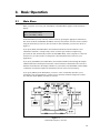
When you power on or reset your 2700 SELECT the Main Menu appears on the instrument
display.
Please select instrument mode
[RUN] [STANDBY] [MENU]
From Main Menu you may enter any of three modes by pressing the appropriate function key.
The modes are RUN, STANDBY and MENU. You may also transfer from one mode to another
using the function keys, however, there are limits to what submenus you can access. Refer to
Figure 3.1.
If you press [RUN] from Main Menu, the instrument initializes and self-calibrates. Once
calibrated it maintains a "sample ready" status. If 2 hours pass without a sample being
processed, the unit automatically transfers to STANDBY Mode, where reagents are conserved.
(In Section 5 you will learn how to change this 2 hour threshold value to better fit your
application.)
If you press [STANDBY] from Main Menu, the instrument flushes buffer through the Sample
Chamber that houses the Enzyme Electrodes. It then continues to flush buffer once an hour to
maintain fresh solution in the Sample Chamber. If you transfer from STANDBY to RUN Mode,
a calibration is initiated to update the calibration reference value stored in memory.
If you press [MENU] from Main Menu, you enter a series of submenus that allow you to
reconfigure your setup parameters, perform service functions and utilize diagnostic routines.
You will learn about MENU selections in Section 5.
Figure 3.1
2700 SELECT Software Structure
3-1
IMPORTANT: The RUN and STANDBY keys act as toggle keys:
You enter RUN Mode by pressing [RUN] and
you exit RUN Mode by pressing [RUN].
You enter STANDBY Mode by pressing [STANDBY] and
you exit STANDBY Mode by pressing [STANDBY].
In each action above you must confirm your intention by pressing [2] or [1] for yes or no,
respectively, then press [ENTER] to confirm your choice.
To enter Run Mode, follow the instructions below.
If required, return to the Main Menu by pressing [MENU] or by exiting RUN or STANDBY
Mode. The display must read as follows:
Please select instrument mode
[RUN] [STANDBY] [MENU]
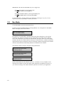
Press [RUN] to enter Run Mode. The Buffer Pump will operate through two cycles and the
instrument will "initialize the baseline current" which means it will ready itself to calibrate.
Two or more calibration cycles will be run automatically. The Sipper moves out of the Sample
Chamber and enters the Calibrator Well or other preset calibrator station. Calibration standard is
aspirated into the Sipper, which then returns to the Sample Chamber and dispenses the standard.
After the measurement, the Buffer Pump flushes the standard from the chamber.
The following display messages will appear during initialization:
Entering RUN mode, please standby
Initializing mechanism...
Entering RUN mode, please standby
Stabilizing baseline current...
Entering RUN mode, please standby
Stabilizing calibration...
NOTE: In Run Mode, the unit calibrates itself every 15 minutes or every 5 samples. It will
sometimes self-calibrate several times until a stable calibration is established. In Section 5.3
you will learn to change some default calibration parameters to better fit your application.
3-2
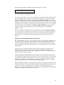
Once a stable calibration is established, the following display will appear:
Ready to sample at Station #2
You are now ready to run a sample.
You may present a sample at any one of several stations: Station #2 (Test Tube Holder Station),
Station #3 (Manual Station), Station #4 (with optional 2710 Turntable), or Station #5 (with
optional 2730 Monitor and Control Accessory). When the “Ready to sample....” screen first
appears, the sample station entered at the Run Mode Setup menu is selected. However, you may
temporarily assign sampling to an alternate station; simply press the number key corresponding
to the number of the station you want to sample from. For example, press the '3' key to change
the prompt from the previous display to ”Ready to sample at Station #3”. The 2700 will
sample from the alternate station until you re-assign sampling or leave the “Ready to
sample....” screen.
Note that if an alternate sampling station is selected when you leave the “Ready to sample....”
screen, the alternate setting will be lost, and the station # stored at the Run Mode Setup menu
will automatically be selected the next time you return. To permanently assign sampling to a
different station, you must enter the Run Mode Setup menu and store a new station # in
memory.
Operation at the Test Tube Holder Station (#2)
The Test Tube Holder (See Figure 3.2) accepts tubes from 9 to 16 millimeters in diameter and
50 to 100 millimeters long. Any container other than a tube with the dimensions indicated
should be presented at the Manual Station (Station #3). Some double-wall plastic tubes may
prevent the fluid detection from working properly. These tubes should also be presented at the
Manual Station.
For the purposes of demonstrating basic operation, choose the high level standard for the
chemistry you are set up to run. For example, if you have installed a YSI 2365 (glucose
oxidase) membrane, calibrate with YSI 2776 standard and use YSI 1531 standard (containing
9.00 g/L dextrose) to run as a sample.
Using the appropriate standard from your starter supplies, fill a test tube about half full. The
Test Tube Holder is hinged at the bottom. Pull out the top as shown in Figure 3.3. Place the tube
in the holder. The Sipper is not designed to pierce septa, but can be used with some flexible
evaporator covers that are preslit. Alternatively, you may use a smaller container and sample
from the Manual Station (#3) to conserve linearity standard solution.
Push the holder back into place. The Test Tube Holder Sensor, located above the holder, detects
the presence of a tube. If a tube is detected, the Sipper will sample from this station; if no tube
is present, it will move to the Manual Station (Station #3). Press [SAMPLE]. The 2700
SELECT will do the rest. The Sipper moves to the sample test tube and immerses itself about 3
millimeters (1/8 inch) below the surface of the fluid.
3-3
Figure 3.2
Sampling Stations
Figure 3.3
The Test Tube Holder Pivoted Out
3-4
The Sipper Pump Piston retracts and draws in 25 microliters of sample. The Sipper moves back
to the Sample Chamber, the Sipper Pump Piston extends and the sample is dispensed. In less
than a minute, the analyte values for the sample are displayed and printed. An example of the
display format is shown below. Notice that the results are shown in line 2, while the “Ready to
sample....” message for the next analysis is in line 1.
Ready to sample at Station #2
B:LAC 0.00 g/L W:GLU 8.98 g/L
The printer format can be configured to express sample ID, date, time, temperature, sample
size, instrument serial number, probe currents and more. See Appendix D for example printouts.
For the purposes of learning basic operation, compare the instrument value with the labeled
value of the YSI standard. The 'linearity' standard should be within ±5% of the label value. For
example, if you calibrated the 2700 SELECT at 2.50 g/L dextrose using YSI 2776 as the
calibrator solution, YSI 1531 (9.00 g/L) should read between 8.55 g/L and 9.45 g/L dextrose. If
the reading falls outside these limits, recalibrate the instrument by pressing [CALIBRATE].
After recalibrating, repeat the analysis as directed above. If your reading is still outside this
range, proceed for now. Later in this section, specific actions for nonlinearity will be addressed.
Operation at the Manual Station (#3)
Remove the tube from the Test Tube Holder. Rotate the Tube Holder back into place. Next press
[3] on the keypad. Note the change in Station # on the LC display. Alternatively, rotate the Test
Tube Holder out to trigger the switch that senses a test tube. The Sipper will automatically go to
Station #3 (Manual).
With the door fully closed, press [SAMPLE]. The display reads:
Manual sample pause
moving MS
Wait for the Sipper to come to a stop at the Manual Station, then bring the sample up to the
Sipper so the tip is just immersed, about 3 millimeters (1/8 inch) below the fluid surface (See
Figure 3.4). If the Sipper dips too deeply into the sample, future measurements may be
contaminated by carry-over of excess sample on the outside of the Sipper.
Be very careful not to jar or push on the Sipper during manual operation. You could disturb its
critical alignment.
The display now reads:
Present sample to needle and hit
[SAMPLE] to aspirate
Press [SAMPLE].
3-5
The sample will be aspirated and the Sipper will return to the Sample Chamber. Do not move
the sample container until the Sipper has returned the Sample Chamber.
Aspirating sample...
The results are then displayed and printed as shown above.
Again compare the value reported by the instrument with the value on the label of the YSI 1531
Standard (9.00 g/L dextrose). Repeat calibration and sampling if the result is not within
specified tolerance limits of ±5% as described above. If your reading is still outside this range,
refer to Linearity Test below.
Figure 3.4
The Manual Station
3-6
If no sample is processed for 2 hours, the 2700 SELECT automatically exits RUN Mode and
enters STANDBY Mode. In STANDBY Mode, the unit conserves reagents. It does not selfcalibrate; it only freshens the Sample Chamber with buffer, using less than 1 milliliter every
hour.
You can manually enter STANDBY Mode from either RUN Mode or the Main Menu by
pressing the [STANDBY] key.
The 2 hour default for entering STANDBY Mode can be changed to better fit your application.
If you have not yet done so, press [MENU]. The following menu should appear.
Select setup: 1-General 2-MeasParameter
3-RunMode 4-Report 5-PrntSetup 6-Default
Press [3] for RunMode.
Then press [2] for AutoStandby. The following display will appear.
Enter autostandby time in hour
0 to disable> 2
If you would like your 2700 SELECT never to leave Run Mode, press [0] and it will
continually self-calibrate and maintain a "sample ready" status. Otherwise, enter the number of
hours (0 to 65,535) you would like to maintain a "sample ready" status before reverting to
STANDBY Mode. Press [ENTER], then [MENU] to return to the Main Menu.
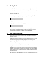
To ensure that your 2700 SELECT is operating properly, perform the following operational
checks on a daily basis.
It is advisable to maintain an instrument log book in which dates and lot numbers of reagents
are recorded, along with information from daily operational checks and other relevant
information. In the log book you may want to paste a printed record of your operational checks.
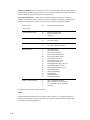
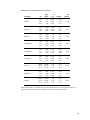
Membrane Integrity Test
Use YSI 2363 Potassium Ferrocyanide (FCN) Standard to determine if your membranes are
structurally intact. This standard is packaged in your starter supplies or may be ordered
separately. The test is semiquantitative, but should offer useful information on "membrane
leakage".
NOTE: This test is recommended for all YSI Enzyme Membranes except Galactose Oxidase
Membranes (YSI 2702). In these membranes FCN is a component of the supply buffer. High
baseline error messages may provide similar information regarding the structural integrity of
the installed membrane.
Place your instrument in RUN Mode. When the unit is ready, the following display will appear.
3-7
Ready to sample at Station #2
Pour a small amount of FCN Standard (1000 mg/dL) into a tube or cup and run it as a sample at
either the Manual or Test Tube Holder Station. The maximum allowable values for FCN
readings after calibrating with YSI standards are listed below.
Chemistry
Membrane
Calibration Standard
FCN Limit
Dextrose
2365
2776, 2747 or 2355
0.05 g/L*
Ethanol
2768
2790 (@ 2.00 g/L)
0.05 g/L*
L-Glutamate
2754
2755
0.06 g/L*
L-Lactate
2329
2776, 2747 or 2327
0.03 g/L*
Sucrose
2703
2780
0.10 g/L*
Choline
2771
2772
0.02 g/L*
L-Glutamine
2735
2736
0.06 g/L*
Methanol
2725
2726 (@ 1.00 g/L)
0.05 g/L*
After a stable calibration with the recommended YSI calibration standard, FCN readings greater
than the limit may indicate membrane structural failure. Recalibrate and repeat the FCN test. If
readings are still high, refer to Section 8, Troubleshooting.
* If you use units other than g/L for the FCN test, refer to Appendix A for conversion values.
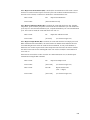
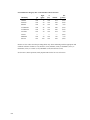
Linearity Test
Use the appropriate YSI linearity standard to test the linear range of the chemistry or
chemistries you have chosen. See the list below to be certain you are testing with the correct
standard solution.
Place your instrument in RUN Mode. When the unit is ready, the following display will appear.
Ready to sample at Station #2
Pour a small amount of linearity standard into a test tube or cup and run it as a sample at either
the Manual or Test Tube Holder Station. NOTE: If there is no test tube in the Test Tube Holder,
the sipper will automatically move to the Manual Station (#3) for aspiration.
Acceptable linearity values for YSI standards are ±5%. See the list of acceptable values below.
3-8
Chemistry
Calibration Std
Linearity Std
Acceptable Range (g/L)*
Dextrose
2776 (2.50 g/L)
1531 (9.00 g/L)
8.55 to 9.45
Ethanol
2790 (2.00 g/L)
2790 (3.20 g/L)
3.04 to 3.36
Lactose
2783 (5.00 g/L)
2784 (25.00 g/L)
23.75 to 26.25
L-Glutamate
2755 (0.73 g/L)
2756 (1.46 g/L)
1.39 to 1.53
L-Lactate
2776 (0.50 g/L)
1530 (2.67 g/L)
2.54 to 2.80
Sucrose
2780 (5.00 g/L)
2778 (25.00 g/L)
23.75 to 26.25
Choline
2772 (0.175 g/L)
2773 (0.450 g/L)
0.43 to 0.47
L-Glutamine
2736 (0.73 g/L)
2737 (1.17 g/L)
1.11 to 1.23
Methanol
2726 (1.00 g/L)
2726 (2.50 g/L)
2.38 to 2.63
If you are setting up to measure galactose or hydrogen peroxide using one of the YSI Enzyme
Membrane Sensors, see Section 4 for more information.
* If you use units other than g/L for the linearity test, refer to Appendix A for conversion
values.
NOTE: If any reading is outside of the specified tolerance limits, recalibrate and repeat the
linearity test. If the reading is still out of tolerance, refer to Section 8, Troubleshooting.
3-9
3-10
The YSI 2700 SELECT has been designed to provide considerable flexibility with respect to
how it may be configured. This allows you to use the instrument for analyses other than the
standard configurations mentioned previously. This flexibility also makes it possible for YSI to
develop and introduce new chemistry analyses in the future without significant instrument
changes.
In this section, you will learn about each of the chemistry measurements that have been
developed for the 2700 SELECT. First, we will briefly discuss the principle of using
immobilized oxidase enzymes. Secondly, we will focus on each standard chemistry setup for
single channel and then dual channel configurations.
You may want to use Section 6.1 to help understand the information presented below regarding
immobilized enzyme sensor technology. You may find Figure 6.1 especially useful.
YSI's enzyme sensor technology employs one or more enzyme catalyzed reactions to ultimately
produce hydrogen peroxide. Hydrogen peroxide (H2O2) is electrochemically oxidized at the
platinum anode of an electrochemical probe. This produces a probe signal current.
In many procedures utilizing enzymes, the enzyme is discarded with the sample after the
analysis is made. YSI's technology allows preservation of the enzyme by immobilizing it in a
patented membrane structure.
The enzyme membrane is coupled with an electrochemical probe and housed in a sample
chamber where sample delivery and flushing occur. The life of the enzyme membrane is
measured in days or weeks, and is not dependent on the number of samples analyzed. If used
frequently, you may measure hundreds of samples with a single enzyme membrane before its
function is compromised.
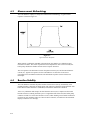
In the sections below, each of the chemistries available by this technology will be discussed. In
enzymology, the terms substrate and product are commonly used to describe a reaction. An
enzyme is a protein molecule with great specificity that catalyzes the conversion of one or more
substrates to one or more products. In the YSI technology, an oxidase enzyme is always
involved since one product of an oxidase reaction is hydrogen peroxide. Hydrogen peroxide is
required to produce a meaningful signal current at the electrochemical probe.
A substrate, like dextrose, enters the sample chamber and is stirred and diluted. The substrate
then diffuses through a thin polycarbonate membrane material. The rate of the chemical
reaction shown below is limited primarily by diffusion. This results in improved linearity,
calibration stability and freedom from enzyme inhibition errors.
4-1
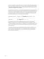
Once past the polycarbonate membrane, the substrate encounters an extremely thin layer of the
appropriate oxidase enzyme. There the following reaction occurs:
Substrate + O2
oxidase
H2O2 + Byproduct
Although oxygen is consumed in this reaction, the buffer is not seriously depleted of oxygen,
nor is the rate of enzyme reaction very sensitive to small changes in oxygen concentration.
Therefore, it is not necessary to measure or control the oxygen content in the sample chamber.
Hydrogen peroxide diffuses toward the platinum anode in the probe assembly. This gives rise to
the probe signal current.
The platinum anode is protected from other oxidizable substances by a thin layer of cellulose
acetate. This makes the anode specific for hydrogen peroxide. Low molecular weight, reducing
compounds can interfere. Typical interferences include phenols, hydrazine, hydrogen sulfide
and mercaptans.
A variety of sample types can be analyzed with the 2700 SELECT. Generally, the only sample
preparation that may be required is dilution of the sample to bring the substrate concentration
within the linear range of the instrument. (see Section 1.4 for the working range of each
chemistry).
Neither color nor turbidity interferes with measurements.
Small particles do not affect the reaction in the sample chamber that houses the probes, but
samples with particles large enough to clog the sipper should be avoided.
Further information and specific procedures for determining the concentration of chemical
analytes in many products or specimens are available in YSI Application Notes. If you would
like to discuss your application or inquire about other uses for the 2700 SELECT, contact YSI
Technical Support (address and phone information on the back cover of this manual).
4-2
In order to configure your instrument to measure a particular chemistry analyte, you need to:
» Approximate the analyte concentration or range of concentrations to be measured.
» Decide if you must dilute your sample, and, if required, determine an appropriate
dilution factor and diluent.
» Decide what calibration value(s) is appropriate for the range of concentrations under
study.
» If possible, account for any interferences to your reading. For example, if you want to
measure starch, free dextrose must be considered. Methods to do these corrections are
described below.
Once you make the above determinations, you can decide whether one of the standard setups
described below will be appropriate or whether you will need to customize your setup. In either
case, the Measurement Parameter section of the instrument Setup Menu lists four submenus in
which you must confirm or assign appropriate parameters. These are sample size, calibration
method, black probe parameters and white probe parameters. If you have a single channel
unit, white probe parameters do not appear in the menu choices.
You may want to access the print setup command in your 2700 SELECT menu. From Run or
Standby mode, press [MENU], then select [5] for PrntSetup. From Main Menu display, press
[MENU], select [2] for Setup, then select [5] for PrntSetup. In either case, the instrument
printer will print a complete list of system parameters.
See Appendix C for more detail on accessing “PrntSetup” and also to review the sample printouts of a single channel unit set for dextrose and a dual channel unit set for simultaneous
dextrose and L-lactate analyses. The parameters you see in these printouts are default values.
For many applications, the default settings will be appropriate for you.
Now enter the Measurement Parameter menu (press [2] for MeasParameter). Within this menu
level you will confirm or change the parameter settings that define the chemistry or chemistries
of interest.
Sample Size (1-SampleSize). The default setting is 25 µL. The range of choices is 5 to 65 µL.
You may enter any integer value. Remember, however, this is a nominal volume. The instrument
does not depend on an accurate absolute value, but rather reproducible aspirations. This allows
the calibrator probe signal to be stored in memory and provide a reference value used to
internally calculate sample readings.
For each chemistry described, a sample size (usually 25 µL) will be recommended. Some of the
reasons for changing that sample size are listed below.
» The calibrator probe signal plateau current might be less than 10 nA. Refer to
Appendix D. You may want to increase the sample size to increase the probe signal.
» Probe plateau current is high enough, but you would like to improve the linear range.
For example, you might decrease sample size from 25 µL to 12 µL. Calibration current
might drop from 20 nA to 10 nA, but accuracy and precision at the upper end of your
concentration range should improve.
» You may want to measure low concentrations of a particular analyte. For example, you
might prepare a 500 mg/L dextrose calibrator for a particular application. If the
dextrose calibrator produces probe signal plateau currents significantly below 10 nA,
you could increase the sample size from 25 to 50 µL (or more) to bring the plateau
current into a reasonable range.
4-3
Calibration Method (2-CalMethod). In most chemistry setups, you will select “One Station”,
and the calibration station # will be “Station #1” (Calibration Well). However, you have options
to configure this in other ways.
» Select One Station, but assign Cal Station #2. Station #2 is the Test Tube Holder
Station. For example, you may place a 500 mg/L dextrose solution in a test tube and
calibrate in this manner. If you choose this option, the sampling position is normally
Station #3 (Manual Station). With accessories, Station #4 (Turntable), or Station #5
(Monitor) may be used.
» If you are running a dual chemistry where a potential interference is involved, you may
select “Two Station”. You will then be prompted to assign calibration stations for both
black and white probes. For example, you could install a sucrose membrane on one
probe and a dextrose membrane on the second probe. You could place sucrose
calibrator in the test tube position (#2) and dextrose at the Cal Well (#1). In this setup,
the instrument is programmed to measure the “dextrose reading” at the sucrose
membrane and automatically subtract it.
Black Probe Parameter (3-Black). In this menu you choose parameters that correspond to the
chemistry of interest at the Black Probe. Be certain that you install the correct enzyme
membrane type. The selections include:
» Chemistry (10 selections, plus “none”)
» Unit of Concentration (g/L, mg/L, mmol/L, %(w/v))
» Calibration value (must correlate to units chosen)
» End Point (basically, the reaction time in the sample chamber)
For most standard applications, recommended parameter settings are outlined below under each
chemistry setup.
White Probe Parameter (4-White). In this menu, you choose parameters that correspond to
the chemistry of interest at the White Probe. Be certain that you install the correct enzyme
membrane type. The selections include:
» Chemistry (10 selections, plus “none”)
» Unit of Concentration (g/L, mg/L, mmol/L, %(w/v))
» Calibration value (must correlate to units chosen)
» End Point (basically, the reaction time in the sample chamber)
For most standard applications, recommended parameter settings are outlined below under each
chemistry setup.
4-4
!
This is a direct reading of dextrose in solution at the enzyme sensor. The enzyme Glucose
Oxidase is immobilized in the YSI Dextrose Membrane.
Dextrose + O2
Glu Oxidase
H2O2 + D-Glucono-δ-Lactone
System Buffer
Calibrator Std
Linearity Std
Black Probe
White Probe
Sample Size
Cal Station
YSI 2357
YSI 2776 (2.50 g/L dextrose)
YSI 1531 (9.00 g/L dextrose)*
YSI 2365 (Dextrose Membrane)
n/a **
25 µL
Station #1 Cal Well
Black Probe Parameters
Chemistry
Unit of Conc
Cal value
End Point
Dextrose
g/L
2.50
30 sec
Note: See Appendix A if concentration unit conversion is required.
* For applications requiring linearity performance to 25.0 g/L, YSI 2777 (25.0 g/L dextrose)
may be used as a linearity standard provided the sample size is 10 µL.
** If you have a dual channel unit, either Black or White, or both Black and White probes can
be configured for this chemistry.
Special Considerations:
» If sample dilution is required, use reagent water or 2357 buffer.
» If a solution must be prepared from solid dextrose, use the following diluent and allow
about 15 minutes before measuring the sample. This is required for dextrose, which
must equilibrate alpha and beta anomers (mutarotational equilibrium). If your reading
is lower than expected, you may need to wait slightly longer for equilibration.
Diluent:
40 g/L NaH2PO4
10 g/L Na2HPO4
Reagent water
Both heat and the presence of phosphate accelerate mutarotational equilibration.
4-5
"
##
This is a direct reading of L-Lactate (L-Lactic Acid) in solution at the enzyme sensor. The
enzyme L-Lactate Oxidase is immobilized in the YSI L-Lactate Membrane.
L-Lactate + O2
L-Lac Oxidase
H2O2 + Pyruvate
System Buffer
Calibrator Std
Linearity Std
Black Probe
White Probe
Sample Size
Cal Station
YSI 2357
YSI 2776 (0.50 g/L L-Lactate)
YSI 1530 (2.67 g/L L-Lactate)
YSI 2329 L-Lactate Membrane
n/a *
25 µL
Station #1 Cal Well
Black Probe Parameters
Chemistry
Unit of Conc
Cal value
End Point
L-Lactate
g/L
0.50
30 sec
* If you have a dual channel unit, either Black or White, or both Black and White probes can be
configured for this chemistry.
Note: See Appendix A if concentration unit conversion is required.
Special Considerations:
» If sample dilution is required, use reagent water or 2357 buffer.
» D-Lactate is not a substrate for L-Lactate Oxidase. Therefore, the 2700 SELECT
cannot directly measure D-Lactate. If you have a known racemic mixture of lactates,
the L-Lactate value multiplied by 2 should give you the total lactate value.
4-6
$
This is a direct reading of sucrose in solution at the enzyme sensor. Three enzymes are coimmobilized in the YSI Sucrose Membrane: Invertase, Mutarotase, and Glucose Oxidase.
Sucrose + H2O
α-D-Glucose
Invertase
Mutarotase
β-D-Glucose + O2
α-D-Glucose + (Fructose)
β-D-Glucose
Glu Oxidase
H2O2 + D-Glucono-δ-Lactone
Through this chain of reactions the moles of hydrogen peroxide liberated is directly
proportional to the moles of sucrose.
System Buffer
Calibrator Std
Linearity Std
Black Probe
White Probe
Sample Size
Cal Station
YSI 2357
YSI 2780 (5.00 g/L Sucrose)
YSI 2778 (25.0 g/L Sucrose)
YSI 2703 Sucrose Membrane
n/a *
25 µL
Station #1 Cal Well
Black Probe Parameters
Chemistry
Unit of Conc
Cal value
End Point
Sucrose
g/L
5.00
30 sec
* If you have a dual channel unit, either Black or White, or both Black and White probes can be
configured for this chemistry.
Note: See Appendix A if concentration unit conversion is required.
Special Considerations:
» If sample dilution is required, use reagent water or 2357 buffer.
» The sample must be dextrose-free, or at least contain levels low enough not to
interfere with the sucrose reading. Since the sucrose membrane contains glucose
oxidase, dextrose will produce a probe signal. See Section 4.16 to measure dextrose
and sucrose simultaneously.
4-7
%
#
This is a direct reading of lactose in solution at the enzyme sensor. The enzyme Galactose
oxidase is immobilized in the enzyme membrane.
Lactose + O2
Gal Oxidase
H2O2 + Galactose Dialdehyde Derivative
System Buffer
Calibrator Std
Linearity Std
Black Probe
White Probe
Sample Size
Cal Station
YSI 2705
YSI 2783 (5.00 g/L Lactose)
YSI 2784 (25.0 g/L Lactose)
YSI 2702 Galactose Oxidase Membrane
n/a *
25 µL
Station #1 Cal Well
Black Probe Parameters
Chemistry
Unit of Conc
Cal value
End Point
Lactose
g/L
5.00
30 sec
* If you have a dual channel unit, either Black or White, or both Black and White probes can be
configured for this chemistry.
Note: See Appendix A if concentration unit conversion is required.
Special Considerations:
» If sample dilution is required, use reagent water.
» The sample should be galactose-free. Galactose and other galactosides such as
raffinose and stachyose are substrates for galactose oxidase. They may interfere by
producing artificially high lactose readings.
» The enzyme membrane integrity test involving the use of YSI 2363 Potassium
Ferrocyanide solution is not informative since ferrocyanide exists in the 2705 system
buffer.
4-8
&
'
This is a direct reading of Ethanol in solution at the enzyme sensor. The enzyme Alcohol
Oxidase is immobilized in the enzyme membrane.
Ethanol + O2
Alcohol Oxidase
H2O2 + Acetaldehyde
System Buffer
Calibrator Std
Linearity Std
Black Probe
White Probe
Sample Size
Cal Station
YSI 2787
YSI 2390 (Solution A, 2.00 g/L)
YSI 2390 (Solution B, 3.20 g/L)
YSI 2786 Alcohol Oxidase Membrane
n/a *
10 µL (for best linearity)
Station #2 Test Tube Holder **
Black Probe Parameters
Chemistry
Unit of Conc
Cal value
End Point
Ethanol
g/L
2.00 g/L
45 sec
* If you have a dual channel unit, either Black or White, or both Black and White probes can be
configured for this chemistry.
** You may use Station #1 (Cal Well), but evaporation through plastic components may be a
problem. See the evaporation control information in special considerations.
Note: See Appendix A if concentration unit conversion is required.
Special Considerations:
» The linear range of ethanol is quite limited. If you are concerned about linearity,
monitor the upper range of concentration on a regular basis. You may benefit by
preparing and using a calibrator with an ethanol concentration close to your sample
concentration .
» If you prepare your own ethanol calibrator, prepare a solution with ionic strength.
Level sensing at Station #2 (Test Tube Holder) depends on a conductive solution. A
0.1% K2EDTA solution as a diluent acts as both a conductive solution and a
preservative. Normal saline solution (0.9%) is also an acceptable diluent.
» Your sample should be methanol-free. Methanol can be a significant interference,
since it is a good substrate for Alcohol Oxidase. Propanol and butanol are very weak
substrates of Alcohol Oxidase and usually do not present an interference problem.
» Controlling evaporation of ethanol from both sample and calibrator is important. The
use of some type of test tube cover (eg., prepunctured film) will help. Frequently
replacing the calibrator solution with fresh solution will also minimize the effects of
evaporation on measurement integrity.
4-9
(
This is an indirect reading of starch by measuring dextrose liberated from the hydrolysis of
starch. To use the method described, your sample must be dextrose-free. If free dextrose is
present, see Special Considerations below.
First, dissolved starch is hydrolyzed externally by the enzyme Amyloglucosidase to produce
dextrose. Dextrose is read at the enzyme sensor. The enzyme Glucose Oxidase is immobilized
in the YSI Dextrose Membrane.
Starch + H2O
Dextrose + O2
Amyloglucosidase
Glu Oxidase
β-D-Glucose (dextrose)
H2O2 + D-Glucono-δ-Lactone
System Buffer
Calibrator Std
Linearity Std
Black Probe
White Probe
Sample Size
Cal Station
YSI 2357
YSI 2776 (2.50 g/L dextrose)
YSI 1531 (9.00 g/L dextrose)*
YSI 2365 Dextrose Membrane
n/a **
25 µL
Station #1 Call Well
Black Probe Parameters
Chemistry
Unit of Conc
Cal value
End Point
Dextrose
g/L
2.50 g/L
30 sec
* For applications requiring linearity performance to 25.0 g/L, YSI 2777 (25.0 g/L dextrose)
may be used as a linearity standard provided the sample size is 10 µL.
** If you have a dual channel unit, either Black or White, or both Black and White probes can
be configured for this chemistry.
Special Considerations:
» An amyloglucosidase enzyme such as Sigma # A7420 works with many samples.
» Solubilizing starch is key to obtaining reproducible results. A variety of methods are in
the literature. YSI has documented a couple of methods in YSI Application notes.
» Prepare a starch solution using the diluent described below, add 1 to 2 mg
amyloglucosidase per mL of starch solution. Allow at least 20 minutes for the enzyme
to react, and the liberated dextrose to reach mutarotational equilibrium, before
measuring the sample. If your reading is higher than expected, you may need to wait
slightly longer, or re-evaluate the possibility of free-dextrose in the sample.
Diluent: 40 g/L NaH2PO4, 10 g/L Na2HPO4, in reagent water.
» If free-dextrose is a concern, first measure free dextrose. Then externally hydrolyze the
starch, and measure the total dextrose after hydrolysis. Subtract the free-dextrose from
the total dextrose and multiply by 0.9 to account for water of hydrolysis.
4-10
)
This is a direct reading of choline in solution at the enzyme sensor. The enzyme Choline
Oxidase is immobilized in the YSI Choline Membrane.
Choline + 2O2
Chol Oxidase
2H2O2 + Betaine
System Buffer
Calibrator Std
Linearity Std
Black Probe
White Probe
Sample Size
Cal Station
YSI 2357
YSI 2772
YSI 2773
YSI 2771(Choline Oxidase Membrane)
n/a *
25 µL
Station #1 Cal Well
Black Probe Parameters
Chemistry
Unit of Conc
Cal value
End Point
Choline
mg/L
175
30 sec
* If you have a dual channel unit, either Black or White, or both Black and White probes can be
configured for this chemistry.
Note: See Appendix A if concentration unit conversion is required.
Special Considerations:
» If sample dilution is required, use reagent water or 2357 Buffer.
» Although the YSI 2772 Choline calibrator solution is prepared using choline bitartrate,
the concentration is expressed as mg/L of choline cation. If you prefer to express the
sample as a salt of choline, you must enter an “adjusted” calibration value when
configuring your instrument measurement parameters.
For example, to express results as a choline hydroxide value, program the calibrator
value as 204 mg/L when using the YSI 2772 Choline Standard calibrator solution. Your
results will now reflect the concentration of choline hydroxide in the sample.
Assumptions and calculations are as follows:
choline hydroxide FW = 121.2
free choline FW = 104.2
(121.1 ÷ 104.2) x 175 mg/L = 203.55 = 204 mg/L (rounded up)
Equivalent values for other choline salts may be calculated in a similar manner.
Potential Interferences. Tests with equimolar concentrations of various vitamins, and other
ingredients of nutritionals, showed little or no interference. On a scale where Choline = 100%,
those substances that produced more than 0.5% response were Riboflavin (1.1%), Pyridoxine
(1.5%), Ascorbic Acid (0.8%), and Thiamine (1.3%). Vanillin, an artificial flavor ingredient,
may produce interference levels exceeding 10% (mole/mole), and should be tested separately
for your individual formulations if known to be present.
4-11
This is a direct reading of galactose in solution at the enzyme sensor. The enzyme Galactose
oxidase is immobilized in the enzyme membrane.
Galactose + O2
Gal Oxidase
H2O2 + Galactose Dialdehyde Derivative
System Buffer
Calibrator Std
Linearity Std
Black Probe
White Probe
Sample Size
Cal Station
YSI 2705
n/a *
n/a *
YSI 2702 Galactose Oxidase Membrane
n/a **
25 µL
Station #1 Cal Well
Black Probe Parameters
Chemistry
Unit of Conc
Cal value
End Point
Galactose
g/L
user's choice (recommend about 2 g/L)
30 sec
* YSI does not currently offer galactose standard solutions.
** If you have a dual channel unit, either Black or White, or both Black and White probes can
be configured for this chemistry.
Note: See Appendix A if concentration unit conversion is required.
Special Considerations:
» If sample dilution is required, use reagent water.
» The sample should be lactose-free. Lactose and other galactosides such as raffinose
and stachyose are substrates for galactose oxidase. They may interfere by producing
artificially high galactose readings.
» The enzyme membrane integrity test involving the use of YSI 2363 Potassium
Ferrocyanide solution is not informative since, ferrocyanide exists in the 2705 system
buffer.
4-12
*+
,
+
This is a direct electrochemical reading of hydrogen peroxide at the enzyme probe. A structure
similar in appearance to an enzyme membrane is used at the probe surface. This membrane
contains immobilized nonenzymatic protein to produce diffusion properties similar to those
exhibited by YSI Enzyme Membranes.
The electrochemical reaction, which is common to all YSI Enzyme Sensors, is the following:
H2O2
+
Platinum anode
2H + O2 + 2e
-
System Buffer
Calibrator Std
Linearity Std
Black Probe
White Probe
Sample Size
Cal Station
YSI 2357 (see note below regarding catalase)
n/a *
n/a *
YSI 270l Blank Membrane
n/a**
25 µL
Station #2 Test Tube Holder
Black Probe Parameters
Chemistry
Unit of Conc
Cal value
End Point
Peroxide
mg/L
user's choice (recommend about 30 mg/L)
30 sec
* YSI does not currently offer hydrogen peroxide standard solutions.
** If you have a dual channel unit, either Black or White, or both Black and White probes can
be configured for this chemistry.
Note: See Appendix A if concentration unit conversion is required.
Special Considerations:
» Since hydrogen peroxide is typically used to calibrate the YSI Blank Membrane, the
enzyme catalase is a concern. Catalase destroys hydrogen peroxide. Catalase occurs
naturally and may be in the sample you are testing. If so, it can also accumulate in the
2700 SELECT sample chamber. A small amount of sodium azide added to the system
buffer will inactivate the catalase. Concentrations around 5 mg/L sodium azide are
appropriate.
» If you have a dual channel 2700 SELECT and suspect an electrochemical interference
(as opposed to an enzymatic interference), you may want to use one channel to
qualitatively monitor for an interference effect.
Typical electrochemical interferences include phenols, mercaptans, hydroxylamine, hydrazine
and analines. If you suspect a particular substance, you may want to configure one of your
probes with a blank membrane and calibrate it as described above under Hydrogen Peroxide.
Then run your sample and check for activity at the Blank Membrane. It is not quantitative, but
may provide useful information about your sample.
4-13
##-+!
This is a direct reading of L-glutamate in solution at the enzyme sensor. The enzyme L-Glutamate Oxidase is immobilized in the YSI Glutamate Membrane.
L-Glutamate + O2
Glut Oxidase
H2O2 + α-Ketoglutarate + NH3
System Buffer
Calibrator Std
Linearity Std
Black Probe
White Probe
Sample Size
Cal Station
YSI 2357
YSI 2755 (5.00 mmol/L glutamate)
YSI 2756 (10.00 mmol/L glutamate)
YSI 2754 (Glutamate Oxidase Membrane)
n/a *
25 µL
Station #1 Cal Well
Black Probe Parameters
Chemistry
Unit of Conc
Cal value
End Point
Glutamate
mmol/L
5.00
30 sec
* If you have a dual channel unit, either Black or White, or both Black and White probes can be
configured for this chemistry.
Note: See Appendix A if concentration unit conversion is required.
Special Considerations:
» If sample dilution is required, use reagent water or 2357 Buffer.
» If you want to measure MSG (monosodium glutamate, monohydrate) and express the
results as mmol/L of MSG, the calibration parameters listed above are all appropriate.
If you want to express results as a w/v measurement, such as mg/L MSG, then
correction for the sodium and water components is necessary.
To express results as an MSG value, change the glutamate units to a w/v expression,
and enter one of the following: 936 mg/L, 0.936 g/L, or 0.094 %. Use YSI 2755
Calibrator Standard (5.00 mmol/L Glutamate) to calibrate the instrument. Sample
results will then reflect MSG concentration.
Potential Interferences. Tests with equimolar concentrations of other amino acids and related
substances showed little or no interference. On a scale where Glutamate = 100%, those
substances that produced more than 0.5% response were L-Aspartate (0.7), L-Tyrosine (1.4), LHistidine (0.7), and L-Glutamine (1.1). Glutamate cannot be ruled out as a contaminant in the
Glutamine solution.
4-14
#
This is a direct reading of glutamine in solution at the enzyme sensor. Two enzymes are coimmobilized in the YSI Glutamine Membrane: Glutaminase and Glutamate Oxidase.
L-Glutamine
Glutaminase
L-Glutamate + O2
L-Glutamate + NH3
Glut Oxidase
H2O2 + α-Ketoglutarate + NH3
Through this chain of reactions the amount of hydrogen peroxide liberated is directly
proportional to the amount of glutamine.
System Buffer
Calibrator Std
Linearity Std.
Black Probe
White Probe
Sample Size
Cal Station
YSI 2357
YSI 2736 (5.00 mmol/L)
YSI 2737 (8.00 mmol/L)
YSI 2735 Glutamine Membrane
n/a *
20 µL
Station #2
Black Probe Parameters
Chemistry
Unit of Conc
Cal value
End Point
Glutamine
mmol/L
5.00
30 sec
* If you have a dual channel unit, either Black or White, or both Black and White probes can be
configured for this chemistry.
Note: See Appendix A if concentration unit conversion is required.
Special Considerations:
» If sample dilution is required, use reagent water or 2357 buffer.
The sample must be glutamate-free, or at least contain levels low enough not to interfere with
the glutamine reading. Since the glutamine membrane contains glutamate oxidase, glutamate
will produce a probe signal. See Section 4.17 to measure glutamate and glutamine
simultaneously.
4-15
"
This is a direct reading of Methanol in solution at the enzyme sensor. The enzyme Alcohol
Oxidase is immobilized in the enzyme membrane.
Methanol + O2
Alcohol Oxidase
H2O2 + Formaldehyde
System Buffer
Calibrator Std
Linearity Std
Black Probe
White Probe
Sample Size
Cal Station
YSI 1579
YSI 2726 (Solution A, 1.00 g/L)
YSI 2726 (Solution B, 2.50 g/L)
YSI 2725 Methanol Membrane
n/a *
15 µL (for best linearity)
Station #2 Test Tube Holder **
Black Probe Parameters
Chemistry
Unit of Conc
Cal value
End Point
Methanol
g/L
1.00 g/L
30 sec
* If you have a dual channel unit, either Black or White, or both Black and White probes can be
configured for this chemistry.
** You may use Station #1 (Cal Well), but evaporation through plastic components may be a
problem. See the evaporation control information in special considerations.
Note: See Appendix A if concentration unit conversion is required.
Special Considerations:
» The linear range of methanol is quite limited. If you are concerned about linearity,
monitor the upper range of concentration on a regular basis. You may benefit by
preparing and using a calibrator with a methanol concentration close to your sample
concentration.
» If you prepare your own methanol calibrator, prepare a solution with ionic strength.
Level sensing at Station #2 (Test Tube Holder) depends on a conductive solution. A
0.1% K2EDTA solution as a diluent acts as both a conductive solution and a
preservative. Normal saline solution (0.9%) is also an acceptable diluent.
» Your sample should be ethanol-free. Ethanol can be a significant interference, since
it is a good substrate for Alcohol Oxidase. Propanol and butanol are very weak
substrates of Alcohol Oxidase and usually do not present an interference problem.
» Controlling evaporation of methanol from both sample and calibrator is important. The
use of some type of test tube cover (eg., prepunctured film) will help. Frequently
replacing the calibrator solution with fresh solution will also minimize the effects of
evaporation on measurement integrity.
4-16
$
+##
You must have a dual channel version of the 2700 SELECT in order to perform this
measurement. Refer to the sections above on DEXTROSE and L-LACTATE for theoretical and
special considerations. Then follow the instructions below to set up your instrument for
simultaneous determination.
Note: In Section 2 of this manual, the step-by-step procedure for setting up this simultaneous
measurement was described.
System Buffer
Calibrator Std
Linearity Std
Black Probe
White Probe
Sample Size
Cal Station
YSI 2357
YSI 2776 (2.50 g/L dex; 0.50 g/L L-lact)
YSI 1531 (9.00 g/L dex) and YSI 1530 (2.67 g/L L-lact)
YSI 2329 L-Lactate Membrane
YSI 2365 Dextrose Membrane
25 µL
Station #1 Cal Well
Black Probe Parameters
Chemistry
Unit of Conc
Cal value
End Point
L-Lactate
g/L
0.50
30 sec
White Probe Parameters
Chemistry
Unit of Conc
Cal value
End Point
Dextrose
g/L
2.50
30 sec
Note: See Appendix A if concentration unit conversion is required.
4-17
%
+
You must have a dual channel version of the 2700 SELECT in order to perform this
measurement. Refer to the sections above on DEXTROSE and SUCROSE for theoretical and
special considerations. Then follow the instructions below to set up your instrument for
simultaneous determination.
Since the Sucrose Membrane (2703) utilizes a chain of enzyme reactions and the final reaction
is a “dextrose measurement”, free dextrose in a sample will be measured at the Sucrose Sensor.
By using the information at the Dextrose Sensor, this free dextrose is automatically subtracted
in the instrument software. The algorithm looks basically like this:
(“Total Dextrose” - “Free Dextrose”) x (1.9) = Sucrose
Total Dextrose is the combined sucrose and dextrose probe signal. Free Dextrose is the dextrose
not derived from sucrose hydrolysis. The constant 1.9 corrects for the weight of fructose that is
not sensed at either probe, and the water of hydrolysis.
System Buffer
Calibrator Std
Linearity Std
Black Membrane
White Membrane
Sample Size
Cal Station
YSI 2357
YSI 2776 and YSI 2780
YSI 1531 and YSI 2778
YSI 2703
YSI 2365
25 µL
Two Station, # 1 (dex), #2 (suc)*
Black Probe Parameters
Chemistry
Unit of Conc
Cal value
End Point
Sucrose
g/L
5.00
30 sec
White Probe Parameters
Chemistry
Unit of Conc
Cal value
End Point
Dextrose
g/L
2.50
30 sec
* Since sucrose calibrator is at the Test Tube Holder, you must sample at the Manual Station
(#3). The Turntable position (#4), and the Monitor Station (#5) may also be used on units
equipped with these accessories.
Special Considerations:
» The combined total of dextrose + sucrose cannot exceed 25 g/L. The dextrose
concentration cannot exceed 10 g/L if the combined total is near 25 g/L, since a
dextrose concentration that high combined with 15 g/L sucrose will saturate the
Sucrose probe. If either of these conditions occur, you should dilute your sample to
bring it into a reasonable range.
» The ability to select sample size (5 to 65 µL) may help you optimize your system,
especially if very high or very low concentrations of one or the other of these
substrates is a problem. The optimal probe current for a calibrator is about 10 nA. See
Menu Diagnostics, Section 5.4, to learn more about measuring your probe signal
before entering Run mode.
Special Considerations continued on other side....
4-18
Special Considerations:(Continued)
» If the dextrose concentration in your sample exceeds the sucrose concentration, the
subtraction of a large dextrose “signal” from a smaller sucrose “signal” may result in
significant errors in the sucrose reading. An alternative method involves using two
different , and appropriate dilutions of the sample to first measure free dextrose, then
treat one sample with invertase and analyze for dextrose liberated from the sucrose.
Contact YSI Customer Service, or your dealer representative for an application note
explaining this approach in detail.
4-19
&
#+#
You must have a dual channel version of the 2700 SELECT in order to perform this
measurement. Refer to the previous sections on L-GLUTAMATE and L-GLUTAMINE for
theoretical and special considerations, then follow the instructions below to set up your
instrument for simultaneous determination.
Since the Glutamine Membrane (2735) utilizes a chain of enzyme reactions and the final
reaction is a “glutamate measurement”, free glutamate in a sample will be measured at the
Glutamine Sensor. By using the information at the Glutamate Sensor, this free glutamate is
automatically subtracted in the instruments software. The algorithm looks basically like this:
(“Total Glutamate” - “Free Glutamate”) = Glutamine
Total Glutamate is the combined glutamine and glutamate probe signal. Free Glutamate is the
glutamate not derived from Glutamine reaction.
System Buffer
Calibrator Std
Linearity Std
Black Membrane
White Membrane
Sample Size
Cal Station
YSI 2357
YSI 2755 and YSI 2736
YSI 2756 and YSI 2737
YSI 2735
YSI 2754
20 µL
Two Station, #1 (glutamate), #2 (glutamine) *
Black Probe Parameters
Chemistry
Unit of Conc
Cal value
End Point
Glutamine
mmol/L
5.00
30 sec
White Probe Parameters
Chemistry
Unit of Conc
Cal value
End Point
Glutamate
mmol/L
5.00
30 sec
* Since glutamine calibrator is at the Test Tube Holder, you must sample at the Manual Station
(#3). The Turntable position (#4) and the Monitor Station (#5) may also be used on units
equipped with these accessories.
Special Consideration:
» The ability to select sample size (5 to 65 µL) may help you optimize your system,
especially if very high or very low concentrations of one or the other of these
substrates is a problem. The optimal probe current for a calibrator is about 10 nA. See
Menu Diagnostics, Section 5.4, to learn more about measuring your probe signal
before entering Run mode.
4-20
In this section you will learn about the specific commands required to move through the 2700
SELECT menu structure. You should begin by studying Figure 5.1 below, recognizing that the
instrument has two operating modes and a menu mode. Also refer to Figure 5.2, next page.
The operating modes are RUN Mode and STANDBY Mode. In RUN Mode the instrument
calibrates, samples or simply remains ready to sample. In STANDBY Mode the instrument
remains powered to keep the probes polarized, and periodically freshens the buffer to the
sample chamber. When entering RUN Mode, the unit will automatically update its calibration as
required.
In MENU Mode there are three submenu levels: Service, Setup and Diagnostics. Notice that
you may move from RUN Mode or STANDBY Mode to limited menus in Setup. However, to
fully access MENU Mode you must exit RUN or STANDBY modes.
Figure 5.1
2700 SELECT Software Structure
To exit RUN Mode press [RUN], then confirm your exit by pressing [2] for Yes, then [ENTER].
The instrument will next display the message shown below.
To exit STANDBY Mode press [STANDBY], then confirm your exit by pressing [2] for Yes,
then [ENTER]. The instrument will also display the message shown below.
The display message shown below is referred to as Main Menu display. This is where we will
begin.
Please select instrument mode
[RUN] [STANDBY] [MENU]
5-1
Please select instrument mode
[RUN] [STANDBY] [MENU]
Figure 5.2
YSI 2700 SELECT Menu Flow Chart
REMEMBER: You move through the 2700 SELECT menus by selecting options on the
display. You can press [MENU] to get back to the Main Menu, and [0] to back up to the
previous display. However, it may be necessary to confirm a response by pressing [ENTER]
before continuing to use the [MENU] or [0] keys.
5-2
Service functions are primarily used during initial setup and anytime reagent changes are made.
Both Cal Pump and Buffer Pump can be primed using this menu level. In addition, Sipper
alignment and Stir Bar speed adjustment can be performed from this level. Use the display
messages and text below to learn the service functions.
Main Menu display:
Please select instrument mode
[RUN] [STANDBY] [MENU]
From Main Menu press [MENU] to display instrument functions.
Select instrument function
1-Service 2-Setup 3-Diagnostic
Press [1] for Service to display service functions.
Select service: 1-Sipper 2-Buffer 3-Cal
4-Stir speed 5-Monitor 6-Turntable
Press [1] for Sipper to initiate Sipper alignment. This procedure was used during initial
instrument setup. Refer to Section 2.9 for more information.
The Sipper Arm Assembly will move to the home position. Loosen the adjustment screw that
holds the Sipper flange to the arm to center the Sipper over the Sample Chamber injection port.
The display messages will guide you through the procedure. It is very important that the Sipper
be accurately adjusted.
Adjust sipper then select
0-Exit 1-Lower sipper for fine alignment
Fine align sipper then select
0-Exit 1-Test sipper position
Select 1 to restart check sipper cycle
0-Exit 1-Home sipper position
Adjust sipper then select
0-Exit 1-Lower sipper for fine alignment
When completed, press [0] for Exit to return to service selections.
Select service: 1-Sipper 2-Buffer 3-Cal
4-Stir speed 5-Monitor 6-Turntable
5-3
Press [2] for Buffer to initiate a 15-second cycle of the Buffer Pump. This selection allows you
to prime the buffer system. Use it after replenishing the buffer bottle or replacing tubing. Also
use it to troubleshoot problems or find leaks.
Select service: 1-Sipper 2-Buffer 3-Cal
4-Stir speed 5-Monitor 6-Turntable
Press [3] for Cal to initiate a 10-second cycle of the Cal Pump. This selection allows you to
prime the calibrator system. Use it after changing the calibration solution or replacing tubing.
Also use it to troubleshoot problems or find leaks.
Select service: 1-Sipper 2-Buffer 3-Cal
4-Stir speed 5-Monitor 6-Turntable
Press [4] for Stir Bar to adjust the stir bar speed. During RUN Mode operation the stir bar has
two operating speeds: normal speed, at which the stir bar rotates smoothly in the chamber and
accelerated speed, at which the stir bar looses synchronization with the motor housed below and
jumps. This jumping action helps clear the sample chamber of air bubbles during a flush cycle.
Adjust until stir bar jumps
1-Increase speed 2-Decrease speed
Using the 1-Increase and 2-Decrease choices adjust the Stir Bar. Lower the speed to observe
synchronous rotation, then increase the speed until the stir bar "jumps" and looses synchronous
rotation. At this point release the [1] key. If jumping does not occur, adjust the Stir Bar speed to
the maximum setting.
Press [0] to exit the stir bar menu level.
Select service: 1-Sipper 2-Buffer 3-Cal
4-Stir speed 5-Monitor 6-Turntable
!
!"" ! # $ "%" &
& " '$$ " "!&
If you press [5] for Monitor, you will access the functions used to align and prime the YSI 2730
Monitor and Control Accessory. Refer to the YSI 2730 Monitor and Control Accessory User’s
Manual for details.
If you press [6] for Turntable, you will access the functions used to align the YSI 2710
Turntable. Refer to the YSI 2710 Turntable Operation Manual for details.
Press [0] two times to backup to the instrument function selections.
Select instrument function
1-Service 2-Setup 3-Diagnostic
You have now completed the Service menu selections.
5-4
(
$
Setup menu is where you will enter system parameters that define the specific information
required to run the 2700 SELECT for your particular application. You will set general
information such as date, time, display and print formats. You will enter specific information
related to chemistry selection, calibration values, concentration units, calibration and sampling
protocols, communication parameters, and other features. Once set, the parameters are
maintained in memory. In the event of power loss, the 2700 SELECT has battery backup to
preserve this information.
NOTE: When first powered, the instrument will contain most of the general information you
need. Some information is set prior to delivery and preserved by battery; and other information
will be set as default values which are appropriate for many standard applications. Use the
display messages and text below to learn the flexibility you have in setting up your 2700
SELECT.
You may find it helpful to use the Menu Flow Chart (Figure 5.2), to follow the menu levels.
Main Menu display:
Please select instrument mode
[RUN] [STANDBY] [MENU]
From Main Menu press [MENU] to display instrument functions.
Select instrument function
1-Service 2-Setup 3-Diagnostic
Press [2] for Setup to display setup selection categories.
Select setup: 1-General 2-MeasParameter
3-RunMode 4-Report 5-PrntSetup 6-Default
Press [1] for General. The display will read:
General setup: 1-Date/Time 2-Contrast
3-RS232 4-Radix 5-Serial# 6-LevelSensor
In General setup menu, you may confirm or change the date, set date format, adjust the display
contrast, define communication parameters, select the radix to express decimal numbers,
confirm or enter the instrument serial number and select whether to deactivate the bottle level
sensor system.
Press [1] for Date/Time. Use the number keys to change entries. Press [ENTER] to confirm
your selection. You will see the display messages below, leading you through the complete date
entry sequence.
Enter date and time as required
Year> 98
5-5
Enter date and time as required
Month> 2
Enter date and time as required
Date> 14
Enter date and time as required
Hour> 17
Enter date and time as required
Minute> 22
Select and/or confirm the format you desire for printed dates; (month/day/year) or
(day/month/year).
Select date format: MM/DD/YY
1-MM/DD/YY 2-DD/MM/YY
When you press [ENTER], you will return to the General setup level.
General setup: 1-Date/Time 2-Contrast
3-RS232 4-Radix 5-Serial# 6-LevelSensor
Press [2] for Contrast. Use the appropriate number key to adjust the LC display contrast for
your comfort. When finished, press [0] to return to General setup level.
Adjust the display contrast
1-Raise contrast 2-Lower contrast
General setup: 1-Date/Time 2-Contrast
3-RS232 4-Radix 5-Serial# 6-LevelSensor
Press [3] for RS232. Use this menu to set communication parameters if you are using the serial
interface port. See Section 9 for detailed information on communications. Below are the display
messages showing default settings and your options. Press [ENTER] to confirm your choices
for each parameter.
If you are not using the serial port, you need not worry about setting these parameters. They
will not interfere with other parameter settings.
RS-232 setup 1-Baud 2-Data 3-Parity
4-Stop 5-Handshake 6-Configuration
Select baud rate: 9600
1-9600 2-4800 3-2400 4-1200 5-600 6-300
5-6
Select number of data bits: Seven bit
1- Seven bit 2-Eight bit
Select parity: Odd
1-None 2-Even 3-Odd 4-Low 5-High
Select number of stop bits: One bit
1-One bit 2-Two bits
Select handshaking type: RTS/CTS
1-RTS/CTS 2-XON/XOFF 3-None
If you choose XON/XOFF, you will go one menu level deeper to enter or confirm XON and
XOFF values.
Enter XON character
> 17
Press [ENTER] to confirm.
Enter XOFF character
> 19
Press [ENTER] to confirm and return to RS-232 setup.
RS-232 setup 1-Baud 2-Data 3-Parity
4-Stop 5-Handshake 6-Configuration
If you press [6] for Configuration, you will see the following.
Select configuration: Non-multidrop
1-Non-multidrop 2-Multidrop
The configuration option allows operation in either a point-to-point environment or in a
multidrop environment with an address (ID) assigned to your 2700 SELECT unit(s). The
default configuration is Non-multidrop. If you press [2] for Multidrop, you will see the
following.
Enter node address
> 38
Either enter another address # or accept the default, then confirm with [ENTER]. The node
address is only used when networking 2700s in a multi-instrument system. The 2700 responds
only to commands prefixed with the ID matching the address assigned from this menu.
5-7
Now press [0] to return to the General setup level.
General setup: 1-Date/Time 2-Contrast
3-RS232 4-Radix 5-Serial# 6-LevelSensor
Press [4] for Radix. In some parts of the world, a "," is preferred to express decimal numbers
(For example: 2.00 = 2,00). Confirm your choice by pressing [ENTER] to return to the General
setup level.
Select radix mark: "."
1-"." 2-",
General setup: 1-Date/Time 2-Contrast
3-RS232 4-Radix 5-Serial# 6-LevelSensor
Press [5] for Serial #. The serial # of your instrument is recorded on the serial plate, lower rear
of case. Enter this number in memory. It will be printed for certain report formats.
NOTE: YSI uses alpha-characters in the serial number. We recommend that you press [SPACE]
for the first alpha-character and omit the last two. Example, 98B01234AB can be entered as
98 01234. This number is normally set prior to delivery, and preserved in memory by battery
backup. Press [ENTER] to confirm and return to General setup level.
Enter instrument serial number
98 01234
General setup: 1-Date/Time 2-Contrast
3-RS232 4-Radix 5-Serial# 6-LevelSensor
Press [6] for Level Sensor. Choose "Yes" to maintain level sensing in the buffer, calibrator and
waste bottles. One reason to inactivate the level sensors would be if you use a non-standard
container for buffer or waste.
Activate bottle level sensors? Yes
1-No 2-Yes
Press [ENTER] to confirm and return to General setup level.
General setup: 1-Date/Time 2-Contrast
3-RS232 4-Radix 5-Serial# 6-LevelSensor
You have now completed General setup. Press [0] to return to Select setup menu level.
Select setup: 1-General 2-MeasParameter
3-RunMode 4-Report 5-PrntSetup 6-Default
5-8
Press [2] for MeasParameter. The display will read:
Measurement parameter setup
1-SampleSize 2-CalMethod 3-Black 4-White
“MeasParameter” is an abbreviation for measurement parameters. In this menu, you may select
the sample size and assign the location of the calibrator solution(s). You will also assign specific
chemistry parameters to the Black probe (single channel) or Black and White probes (dual
channel). These parameters include chemistry assignment, calibration value, units of
concentration, and time to endpoint of the enzyme sensor reading.
NOTE: YSI has assigned default values for each of these parameters, but provides flexibility for
the user to change values to optimize for a particular application.
Press [1] for SampleSize. The default setting is 25 microliters. The range is 5 to 65.
Enter sample size in microliter
> 25
Press [ENTER] to confirm and return to Measurement parameter setup.
Measurement parameter setup
1-SampleSize 2-CalMethod 3-Black 4-White
Press [2] for CalMethod. The default setting is One station. The Two Station option is required
for some dual channel analyses, for example, simultaneous dextrose and sucrose determination.
Select calibration method: One station
1-One station 2-Two stations
After pressing [ENTER] to confirm One station, you must specify at which location the
calibration solution will be. The default location is Station #1 (Cal Well). The choices are #1
and/or #2. Number 2 is the Test Tube Holder location. With Accessories such as the YSI 2710
Turntable and YSI 2730 Monitor and Control Accessory, stations #4 and #5 are also options.
Enter Cal Station #
> 1
NOTE: If Two station is selected, you will first be prompted to identify the Black probe cal
station #, and then the White probe cal station #.
Press [ENTER] to confirm and return to Measurement parameter setup.
Measurement parameter setup
1-SampleSize 2-CalMethod 3-Black 4-White
Press [3] for Black. At this level, you will choose chemistry and other black probe measurement
parameters.
Select BLACK chemistry: L-Lactate
0-Backup 1-Next chemistry [ENTER]-Accept
5-9
Press [1] for Next chemistry to scroll through the choices in the menu. The choices are LLactate, Sucrose, Lactose, Galactose, Peroxide, Ethanol, Choline, L-Glutamate, L-Glutamine,
Methanol, none, and Dextrose. The Black probe default chemistry is L-Lactate.
Press [ENTER] to confirm and continue to the unit of measurement parameter. The choices are
grams/liter (g/L), millimoles/liter (mmol/L), milligram/liter (mg/L), which is often referred to
as parts per million (ppm), and percent (weight/volume).
Select BLACK unit of measurement: g/L
1-mmol/L 2-mg/L 3-g/L 4-% (w/v)
To confirm, press [ENTER], then choose the calibration value. For L-Lactate the default value
is 0.50 g/L. If you change units, default values automatically change to reflect the new units of
measurement. If you are not using a calibrator with the default value, you must enter the new
value after a change of units. Use Appendix A to convert to the appropriate value.
Enter BLACK calibration value in g/L
> 0.50
For some numeric entries you may need to lead with a 0. Follow the cursor. For example, if you
had 13.89 mmol/L Dextrose entered, and you wanted to change to 1.80 g/L, the calibration
value would read “02.50”, with the cursor under the “0”. You would then need to enter 1.80 as
01.80.
To confirm, press [ENTER], and then choose the end point time for the stabilized enzyme
sensor reading. The default is 30 seconds. The range is 15 to 125 seconds. Use the default
setting unless a particular application instruction specifies another value.
Enter BLACK end point time in seconds
> 30
Press [ENTER] to confirm and return to the Measurement parameter setup.
Measurement parameter setup
1-SampleSize 2-CalMethod 3-Black 4-White
If you have a dual channel unit, press [4] for White, and repeat the steps that you performed for
the Black probe. The default settings are Dextrose, g/L, 2.50, 30 seconds. All of the setup
options for the Black probe are also available for the White probe.
Select WHITE chemistry: Dextrose
0-Backup 1-Next chemistry [ENTER]-Accept
Press [ENTER] to confirm Dextrose as the WHITE chemistry.
Select WHITE unit of measurement: g/L
1-mmol/L 2-mg/L 3-g/L 4-%(w/v)
Enter WHITE calibration value in g/L
> 2.50
5-10
Enter WHITE end point in seconds
> 30
Press [ENTER] to confirm and return to Measurement parameter setup.
Measurement parameter setup
1-SampleSize 2-CalMethod 3-Black 4-White
You have now completed MeasParameter setup. Press [0] to return to the Select setup level.
Select setup: 1-General 2-MeasParameter
3-RunMode 4-Report 5-PrntSetup 6-Default
Press [3] for RunMode. The display will read:
RUN mode setup: 1-SampleProtocol
2-AutoStandby 3-AutoCal 4-Monitor
In this menu, you select parameters related to sampling protocol, set parameters that control
automatic switching to standby mode and select parameters that will trigger autocalibrations. In
Sampling Protocol, you can select the sample station (position), activate replicate sampling and
sample identification systems, and set the position to which the Sipper descends when sampling
at the Manual Station.
Press [1] for SampleProtocol. The display will read:
Sampling protocol setup: 1-SipperHeight
2-Replicates 3-ID 4-Station# 5-Turntable
Press [1] for SipperHeight. This specifies to what vertical position the Sipper descends when
sampling at the Manual Station (#3). For example, with long test tubes and the fluid level near
the bottom of the test tube, use "Low" setting.
Select manual sipper height: Medium
1-Low 2-Medium 3-High
Press [ENTER] to confirm and return to Sampling protocol setup.
Sampling protocol setup: 1-SipperHeight
2-Replicates 3-ID 4-Station# 5-Turntable
Press [2] for Replicates. The default setting is No. The display prompts reflect messages for
single sampling and single calibrations. If Yes is confirmed, you will be prompted at the display
each time you press [SAMPLE] or [CALIBRATE] to enter how many times the sample or cal
solution should be run for that one command. The number that you assign to Replicates must be
between 1 and 999 (samples or calibrations). During RUN Mode, you may cancel the assigned
number of replicate cycles by pressing [CANCEL].
As an example, Replicates allows you to configure your system to run a sample in the Test Tube
Holder unattended in duplicate or triplicate. Replicates also allows you to check calibration
stability by assigning some number of consecutive calibrations to be run without requiring
repeated key commands of [CALIBRATE].
5-11
Prompt replicate cycle? No
1-No 2-Yes
Press [ENTER] to confirm and return to Sampling protocol setup.
Sampling protocol setup: 1-SipperHeight
2-Replicates 3-ID 4-Station# 5-Turntable
Press [3] for ID. If you wish to assign sample identification numbers to each sample, enter [2]
for Yes here. When you press [SAMPLE] in RUN Mode, the display will prompt you to enter a
sample ID number. You may elect not to assign a number for each sample, in which case the
prompt display disappears and the sample is run identified only by time and date.
Prompt sample ID? No
1-No 2-Yes
Press [ENTER] to confirm and return to Sample protocol setup.
Sampling protocol setup: 1-SipperHeight
2-Replicates 3-ID 4-Station# 5-Turntable
Press [4] for Station# to assign the position at which the sample will be aspirated. The default
location is Station #2, the Test Tube Holder station. You may also elect to sample from Station
#3, the Manual Station or even Station #1, the Cal well. This last choice would be rarely used,
but does give you the flexibility to calibrate from a solution in the Test Tube Holder (#2) and
sample from the Cal Well (#1). If you have the YSI 2710 Turntable or YSI 2730 Monitor and
Control Accessory, stations #4 and #5 are also available. See the appropriate manual for
assignments.
Enter Sample Station#
>2
Press [ENTER] to confirm and return to Sampling protocol setup.
Sampling protocol setup: 1-SipperHeight
2-Replicates 3-ID 4-Station# 5-Turntable
$)*# !
%+, ! ! Refer to the YSI 2710 Turntable Operation Manual for setup, operation and maintenance of the
turntable.
Press [0] to return to RUN mode setup.
RUN mode setup: 1-SampleProtocol
2-AutoStandby 3-AutoCal 4-Monitor
5-12
Press [2] for AutoStandby to define the number of hours the unit will continue to update
calibration and be ready to sample. The default setting is 2. If you press [0] and confirm with
[ENTER], AutoStandby is disabled. The instrument then remains "sample ready" indefinitely.
You may enter any number between 0 and 999.
Enter autostandby time in hour
0 to disable> 2
Press [ENTER] to confirm and return to RUN mode setup.
RUN mode setup: 1-SampleProtocol
2-AutoStandby 3-AutoCal 4-Monitor
Press [3] for AutoCal to define parameters that initiate autocalibrations. The five categories are
shown in the display below. The default settings that initiate calibration are: 1) temperature drift
of more than 1°C since last cal, 2) after 15 minutes without cal update, 3) after 5 samples run
without a cal update, 4) after a probe current shift of 2% or greater compared to the last cal, and
5) after certain errors are detected (eg., baseline instability).
Autocal setup: 1-Temperature 2-Time
3-Sample 4-Cal shift 5-Sample error
You may alter any of these parameters to suit your application, however, you may compromise
precision and/or accuracy when doing so. YSI's stated specifications are based on the default
settings shown above.
-./0-' ! $ "
# ! !1&
" &
"$"$
2 &&
$!& #&$#" ' $$$ 3 & '
These selections are provided as part of the overall concept of the 2700 SELECT, flexibility.
You may have an application where 5% precision is acceptable if you can guarantee that the
instrument will not initiate a calibration at a critical sampling time. This menu allows you to
make that possible.
The 5 autocal parameter displays are shown below with their default values. The range of
values that may be entered is shown below each display. Press [ENTER] to confirm each
parameter and proceed to the next.
Press [1] for Temperature.
Enter allowable autocal temp drift in °C
0 to disable> 1
Confirm value shown or enter and confirm number of degrees from 1 to 20.
5-13
Autocal setup: 1-Temperature 2-Time
3-Sample 4-Cal shift 5-Sample error
Press [2] for Time.
Enter autocal time interval in minute
> 15
Confirm value shown or enter and confirm any number of minutes from 0 to 30000.
Autocal setup: 1-Temperature 2-Time
3-Sample 4-Cal shift 5-Sample error
Press [3] for Sample.
Enter number of samples between autocals
0 to disable> 5
Confirm value shown or enter and confirm any number of samples from 0 to 30000.
Autocal setup: 1-Temperature 2-Time
3-Sample 4-Cal shift 5-Sample error
Press [4] for Cal shift.
Enter allowable autocal shift in %
0 to disable> 2
Confirm value shown or enter and confirm any number from 0 to 100.
Autocal setup: 1-Temperature 2-Time
3-Sample 4-Cal shift 5-Sample error
Press [5] for Sample error.
Autocal on sample error? Yes
1-No 2-Yes
Press [ENTER] to confirm performing an Autocal whenever a sample error is detected, or press
[1] for No, then [ENTER] if you do NOT want the 2700 to perform an Autocal after detecting
an error.
Autocal setup: 1-Temperature 2-Time
3-Sample 4-Cal shift 5-Sample error
5-14
Press [0] to return to RUN mode setup.
RUN mode setup: 1-SampleProtocol
2-AutoStandby 3-AutoCal 4-Monitor
You have now completed Run mode setup. Press [0] to return to Select setup menu level.
Select setup: 1-General 2-MeasParameter
3-RunMode 4-Report 5-PrntSetup 6-Default
Press [4] for Report. The display will read:
Select sample report format: Brief
1-None 2-Brief 3-Detail
Press [ENTER] to confirm sample report format and move to cal report format.
Select cal report format: Brief
1-None 2-Brief 3-Detail
Report Format refers to the information that will be printed each time the 2700 SELECT runs a
sample or a calibration. The default settings are "Brief".
Detail report formats are typically used when you want to study probe currents and temperature
changes with newly installed reagents or enzyme membranes. You may also elect to choose
Detail report for the first few calibrations or samples after a long idle period where no samples
or cals are run. If you suspect problems with the instrument, you should run Detail reports to
provide more information for troubleshooting.
See Appendix D for example report formats.
Press [0] to return to Select Setup.
Select setup: 1-General 2-MeasParameter
3-RunMode 4-Report 5-PrntSetup 6-Default
You have completed Report setup.
Press [5] for PrntSetup. The display will read:
Printing instrument setup... Please wait
The instrument will print the setup information you have entered. The information is an
itemized list of the key parameters that you have chosen. The printing will take about 60
seconds and use about 8 inches (20 cm) of printer paper. See Appendix C for a sample printout.
When printing is completed, the instrument returns to Select setup menu.
5-15
Select setup: 1-General 2-MeasParameter
3-RunMode 4-Report 5-PrntSetup 6-Default
You have completed Print Setup (PrntSetup) level.
Press [6] for Default. The display will read:
Reset all system parameters? No
1-No 2-Yes
This menu allows you to reset all system parameters to the default settings, that is, those that
reside in ROM (Read Only Memory) when the instrument is manufactured. DO NOT DO THIS
AT THIS TIME! If you have been entering setup information for a particular application,
resetting to Default will clear some or all of your selections and restore Default system
parameters.
You will likely use Default to return to YSI-recommended settings if you have been
experimenting with the selections and would like to start at the beginning.
Press [ENTER] to confirm your choice and return to Select setup.
Select setup: 1-General 2-MeasParameter
3-RunMode 4-Report 5-PrntSetup 6-Default
Press [0] to return to Select instrument function.
Select instrument function
1-Service 2-Setup 3-Diagnostic
YOU HAVE NOW COMPLETED THE SETUP MENU OF THE SOFTWARE.
As you gain more familiarity with the 2700 SELECT menus, the setup will not seem so
complicated. You will learn to "jump in and out" of the menus quickly, sometimes not even
needing to exit RUN or STANDBY mode to make a change.
When you have completed Service, Setup or Diagnostic functions press [0] (or [MENU]) to
return to Main Menu. From Main Menu you may enter RUN or STANDBY modes.
Please select instrument mode
[RUN] [STANDBY] [MENU]
5-16
4
'
Diagnostic menu functions are used primarily during troubleshooting. In this menu, you will
learn to gain individual control of components in the instrument. For example, you can turn
motors on and off, and even "exercise" motor-controlled devices. You can run pumps to check
fluid movement. You can check probe electrical current and even simulate a calibration or
sample cycle. You can check I/O (input/output) devices such as display, keypad and printer for
proper function. And finally, you can check the status of most sensors in the system. These
include the temperature sensor in the Sample Chamber; the level sensors in the reagent and
waste bottles; the Sipper capacitance sensing; and the optical sensors that control motors, the
Sipper Pump and sense the Test Tube Holder position.
Follow the display prompts and information below to learn about the 2700 SELECT menu
diagnostics mode. As before, you will often need to press [0] to return to a previous menu level.
Occasionally, the instrument will print diagnostic information.
Refer to Figure 5.3 below to become familiar with major components of the instrument.
Additional figures in Sections 3 and 5 may be useful, especially Figure 5.2, Menu Flow Chart.
Figure 5.3
2700 SELECT Major Components
5-17
As discussed in the Introduction to this section, you must exit RUN Mode or STANDBY Mode
to gain complete access to the diagnostic menu functions. To exit Run or Standby modes, press
the appropriate key ([RUN] or [STANDBY]), then follow the prompts to exit. You will now be
in Main Menu mode and the display will appear as shown below.
Please select instrument mode
[RUN] [STANDBY] [MENU]
Press [MENU], then [3] for Diagnostic to display the five categories of diagnostic selections.
Select instrument function
1-Service 2-Setup 3-Diagnostic
Select diagnostic
1-Motor 2-Pump 3-Probe 4-I/O 5-Sensor
Press [1] for Motor to gain access to two motors, the Sipper Arm assembly (vertical and
horizontal motions) and the Stir Motor that turns the magnetic stir bar in the Sample Chamber.
Motor diagnostic
1-Sipper motor 2-Stir motor 3-Turntable
Press [1] for Sipper motor to display the following motion selections.
Sipper diagnostic: 1-Up 2-Down 3-Home
4-Clockwise 5-Counterclock 6-Exercise
When you press one of the keys (1-5), a movement of the Sipper should be observed. Press [1]
and the Sipper moves up until the upper limit optosensor is detected. Press [2] and the Sipper
moves down into the Sample Chamber or to its limit, if at another station.
05#& 6
7 $ 1"# $ $ " '#$$" !
"$#& !
" $$&1 $ 8
&!"
In the horizontal plane, press [3] and the Sipper moves to the position directly over the Sample
Chamber opening. Press [4] and the Sipper moves horizontally clockwise one station, for example from "home" to Test Tube Holder Station (Station #2). Press [5] and the Sipper moves
horizontally counterclockwise one station, for example from Manual Station (Station #3) to
Test Tube Holder Station (Station #2).
NOTE: If the Sipper is "down" and you press a command for horizontal movement, the Sipper
first moves up before beginning horizontal motion.
5-18
Press [6] to initiate repeated motions in the same plane. We refer to this as" Exercise". The
motion (horizontal or vertical) is determined by the last command you chose. The instrument
counts the number of cycles and displays them as shown below. When you press a key to
terminate the exercise mode, the printer records the activity and number of cycles completed.
Exercising sipper motor
Cycle = 3 Hit any key to stop
Press [0] to return to Sipper diagnostic selections.
Sipper diagnostic: 1-Up 2-Down 3-Home
4-Clockwise 5-Counterclock 6-Exercise
Press [0] again to return to Motor diagnostic selections.
Motor diagnostic
1-Sipper motor 2-Stir motor 3-Turntable
Press [2] for Stir motor to turn on the motor that spins the magnetic stir bar in the Sample
Chamber. The bar should spin in "synch", i.e., not "jump" about the chamber as is observed
during brief periods of normal operation. The asynchronous motion is used to dispel air bubbles
from the chamber wall and probe surfaces.
You turn the Stir Motor off by pressing [2] again. The Stir motor may be activated with the
Sipper either in or out of the Sample Chamber.
Motor diagnostic
1-Sipper motor 2-Stir motor 3-Turntable
Press [0] to return to the five diagnostic selections.
Select diagnostic
1-Motor 2-Pump 3-Probe 4-I/O 5-Sensor
Press [2] for Pump to access the Sipper Pump, Calibrator Pump and Buffer Pump.
Pump diagnostic
1-SipperPump 2-Buffer 3-Cal 4-ExtPump
Press [1] for Sipper Pump to begin a sequence of five distinct movements of the plunger rod in
the Sipper Pump. Locate the Sipper Pump, a clear plastic cylindrical body mounted between the
two peristaltic pumps on the fluid wall. See Figure 5.3. Focus on the metal plunger rod inside
this plastic body. Some movements will be brief, so watch closely.
Sipper pump diagnostic
1-Home
Press [1] for Home. You will see a small movement of the plunger, but you will hear a clicking
sound that lasts 3 or 4 seconds as the pump motor oversteps to detect "home".
5-19
The display will now update to give two new selections as shown below.
Sipper pump diagnostic
1-Home 2-Aspirate separator 3-Exercise
Press [2] for Aspirate separator. A short retraction of the plunger should occur. This simulates
the aspiration of an air bubble to isolate sample from the buffer stream. The display updates to
read the following.
Sipper pump diagnostic
1-Home 2-Aspirate sample 3-Exercise
Press [2] for Aspirate sample. A longer retraction of the plunger should occur. This simulates
the aspiration of sample. The display updates to read the following.
Sipper pump diagnostic
1-Home 2-Dispense sample 3-Exercise
Press [2] for Dispense sample. An extension of the plunger should occur. This simulates
dispensing the sample into the Sample Chamber. The display updates to read the following.
Sipper pump diagnostic
1-Home 2-Dispense separator 3-Exercise
Press [2] for Dispense separator. A short extension of the plunger should occur. This simulates
dispensing the air bubble into the Sample Chamber after the sample reading at the probe would
have occurred. The plunger is now back to "home" position.
Sipper pump diagnostic
1-Home 2-Aspirate separator 3-Exercise
Press [3] for Exercise. All of the plunger movements will occur in the sequence described
above. The complete retraction and extension represents one cycle. The cycle number is
displayed.
Exercising sipper pump
Cycle = 3 Hit any key to stop
When you press a key to terminate the exercise mode, the printer records the activity and
number of cycles completed. The display returns to Sipper pump diagnostic menu.
Sipper pump diagnostic
1-Home 2-Aspirate separator 3-Exercise
Press [0] to return to Pump diagnostic menu.
Pump diagnostic
1-SipperPump 2-Buffer 3-Cal 4-ExtPump
5-20
Press [2] for Buffer to turn on the Buffer Pump. The pump runs until you press [2] a second
time. The display does not change messages during this activity. You should hear the pump and
see fluid moving through the Sample Chamber and exiting through the opening of the steel
cone, then through the Waste Tube to the Waste Bottle.
Pump diagnostic
1-SipperPump 2-Buffer 3-Cal 4-ExtPump
Press [3] for Calibrator to turn on the Calibrator Pump. The pump runs until you press [3] a
second time. The display remains as shown below. You should hear the pump and see fluid
moving into the Cal Well of the Sample Chamber Block, and then flowing out through the
Waste Tube to the Waste Bottle.
Pump diagnostic
1-SipperPump 2-Buffer 3-Cal 4-ExtPump
Press [0] to return to the five diagnostic selections.
NOTE: Unless the 2730 Monitor and Control pump is installed, 4-ExtPump will give no
response, Refer to the YSI 2730 Monitor and Control Accessory User’s Manual for details of
external pump operation.
Select diagnostic
1-Motor 2-Pump 3-Probe 4-I/O 5-Sensor
Press [3] for Probe. You will observe a brief display message, as shown below, which then
changes to show probe current(s). You will observe only Black probe current for a single
channel unit. The probe activity is expressed in nA (nanoamperes) of electrical current.
-9
A nanoampere is 10 amperes, which is a very low level of electrical current.
Reading probe current...
Please wait.
B:LAC 0.50 nA W:DEX 1.76 nA
1-Flush 2-Calibrator 3-Sample
NOTE: If you assign "none" for a probe in the Setup (measurement parameters) menu, or you
have a single channel unit, the display appears as shown below.
B:LAC 0.50 nA W: -Not assigned1-Flush 2-Calibrator 3-Sample
Press [2] for Calibrator. The Calibrator Pump turns on as the Sipper moves to the Cal Well and
descends. Calibrator solution is aspirated, then moved to the Sample Chamber and dispensed,
just as you would observe in a normal calibration cycle.
The display probe current should rise above baseline and within 20 to 30 seconds should level
off at some nanoampere value indicative of the particular chemistry and aspiration volume you
have setup.
5-21
B:LAC 11.77 nA W:DEX 23.17 nA
1-Flush 2-Calibrator 3-Sample
Next, press [1] for Flush to clear the calibrator solutions from the Sample Chamber. The flush
will take about 30-40 seconds. If the baseline has not returned to levels you previously
observed, you may want to initiate a second flush cycle. Baseline values are shown again below.
B:LAC 0.55 nA W:DEX 1.80 nA
1-Flush 2-Calibrator 3-Sample
Press [3] for Sample. The Sipper will move to the assigned sample station and aspirate sample,
then move to the Sample Chamber to dispense sample, just as was observed in the calibrator
cycle above. Again, you must initiate the flush cycle by pressing [1] for Flush. Probe current
values will vary based on concentrations used for sampling.
B:LAC 91.83 nA W:DEX 112.9 nA
1-Flush 2-Calibrator 3-Sample
Press [0] to return to the five diagnostic selections.
Select diagnostic
1-Motor 2-Pump 3-Probe 4-I/O 5-Sensor
Press [4] for I/O. From this menu level you can run diagnostic tests on the input/output devices
of the instrument.
I/O diagnostic
1-Keypad 2-Display 3-Printer
Press [1] for Keypad. You may now test each of the 20 keys on the keypad. There are 12
numeric keys (including space and backspace) and 8 function keys. To exit the keypad test,
press and hold [CANCEL].
Hit keys - Hold [CANCEL] to exit
Key>
When you press and immediately release a key, we refer to this as a “hit". The following will be
displayed (example is [RUN] key).
Hit keys - Hold [CANCEL] to exit
Key> [RUN] hit
When you press and hold a key down and then release it, the following display messages should
be observed.
Hit keys - Hold [CANCEL] to exit
Key> [RUN] held down
5-22
Hit keys - Hold [CANCEL] to exit
Key> [RUN] released
To exit the keypad test, press and hold down the [CANCEL] key.
Hit keys - Hold [CANCEL] to exit
Key> [CANCEL] held down
The following message appears after you exit the keypad test.
I/O diagnostic
1-Keypad 2-Display 3-Printer
Press [2] for Display. You should now see 95 different characters (including a blank) appear in
each of the 40 segments of the liquid crystal display. The total test takes about 40 seconds.
Terminate the test at any time by pressing any key. The first few characters are shown below.
!!!!!!!!!!!!!!!!!!!!!!!!!!!!!!!!!!!!!!!!!!!!!!!!!!!!!!!!!!!
!!!!!!!!!!!!!!!!!!!!!!!!!!!!!!!!!!!!!!!!!!!!!!!!!!!!!!!!!!!
""""""""""""""""""""""""""""""""""""
""""""""""""""""""""""""""""""""""""
#######################################
#######################################
$$$$$$$$$$$$$$$$$$$$$$$$$$$$$$$$$$$$$$$
$$$$$$$$$$$$$$$$$$$$$$$$$$$$$$$$$$$$$$$
I/O diagnostic
1-Keypad 2-Display 3-Printer
Press [3] for Printer. The printer prints the same 95 characters described above in the display
test. The printout uses 5 lines and takes about 10 seconds to complete. The display momentarily
flashes the message "Printer test", then returns to I/O diagnostic menu.
Printer test
I/O diagnostic
1-Keypad 2-Display 3-Printer
5-23
Press [0] to return to the five diagnostic selections.
Select diagnostic
1-Motor 2-Pump 3-Probe 4-I/O 5-Sensor
Press [5] for Sensor. You may select one of three categories of sensors: temperature, fluid level
or detection, and optosensors for a variety of motion status signals.
Sensor diagnostic
1-Temperature 2-LevelSensor 3-OptoSensor
Press [1] for Temperature. The display shows the current temperature of buffer in the Sample
Chamber. The temperature display is "live", i.e., changes will be updated continuously.
Reading sample chamber temperature...
Please wait
Sample chamber temperature: 25.10 C
Hit any key to exit
Press any key to return to Sensor diagnostic menu.
Sensor diagnostic
1-Temperature 2-LevelSensor 3-OptoSensor
Press [2] for LevelSensor. You will observe the current status of each of the four level sensors
shown below. The Sipper will show "fluid" or "air". The Cal and Buffer will show "OK" or
"Empty". The Waste will show "OK" or "Full".
Level sensor status: Sipper:Fluid
Cal:OK Waste:OK Buffer:Empty
Press [0] to return to Sensor diagnostic menu.
Sensor diagnostic
1-Temperature 2-LevelSensor 3-OptoSensor
Press [3] for OptoSensor. Optosensors are used to track horizontal and vertical movement of the
Sipper, the movement of the Sipper Pump plunger and the presence of a test tube in the Test
Tube Holder.
Opto sensor status: Horiz:OFF Vert:ON
SipperPump:ON TestTube:ON
If the Sipper is positioned at Station #2 or #3, the Horiz message should be OFF; if at "home"
or Station #1, the message should be ON.
If the Sipper is down in the Sample Chamber, the Vert message should be OFF; if up, the
message should be ON.
5-24
If the Sipper Pump plunger is at "home", i.e. extended, the SipperPump message should be ON;
if the plunger is in any position other than home, the message should be OFF.
If there is a test tube in the Test Tube Holder and it is in a vertical orientation, the "TestTube"
message should be ON; if not, then the message should be OFF.
Press [0] to return to Sensor diagnostic menu.
Sensor diagnostic
1-Temperature 2-LevelSensor 3-OptoSensor
Press [0] to return to the five diagnostic selections.
Select diagnostic
1-Motor 2-Pump 3-Probe 4-I/O 5-Sensor
Press [0] to return to Select instrument function.
Select instrument function
1-Service 2-Setup 3-Diagnostic
Press [0] to return to Main Menu display.
Please select instrument mode
[RUN] [STANDBY] [MENU]
NOTE: You may press [MENU] from most levels of diagnostics to return directly to Main
Menu.
You now have had a complete look at the Diagnostic Menu. You may press [RUN] or
[STANDBY] to enter an operating mode, or remain in Main Menu indefinitely, however, note
that no automatic calibrations or sample chamber flushes will occur in this mode.
5-25
5-26
The sensor technology of the YSI 2700 SELECT is based on the principles conceived by Dr.
Leland Clark of Children’s Hospital Foundation, Cincinnati, Ohio. The immobilized enzyme
membrane was invented by YSI and is covered by U.S. Patent 4,073,713. This sensor
technology has been used successfully since 1975 in the YSI 23A Blood Glucose Analyzer;
then later in the YSI 27 Industrial Analyzer and the YSI 23L Blood Lactate Analyzer. Most
recently, the same technology has been employed in the YSI 2300 STAT PLUS Glucose and LLactate Analyzer and the YSI 1500 SPORT Lactate Analyzer.
Figure 6.1
Sensor Probe and Enzyme Membrane
Each probe is fitted with a three-layer membrane containing immobilized enzyme in the middle
layer. Figure 6.1 shows an exploded view of the membrane and its relationship to face of the
probe.
6-1
The face of the probe, covered by the membrane, is situated in a buffer-filled sample chamber
into which a sample is injected. Some of the substrate diffuses through the membrane. When it
contacts the immobilized oxidase enzyme, it is rapidly oxidized, producing hydrogen peroxide.
See Reaction 1, using glucose as an example.
The hydrogen peroxide (H2O2) is, in turn, oxidized at the platinum anode, producing electrons
(Reaction 2). A dynamic equilibrium is achieved when the rate of H2O2 production and the rate
at which H2O2 leaves the immobilized enzyme layer are constant and is indicated by a steady
state response (Figure 6.3). The electron flow is linearly proportional to the steady state H2O2
concentration and, therefore, to the concentration of the substrate.
REACTION 1 (glucose):
β-D-glucose + O2
REACTION 2:
H2O2
GOx
+
Pt anode
Glucono-δ-lactone + H2O2
2H + O2 + 2e
-
The platinum electrode is held at an anodic potential and is capable of oxidizing many
substances other than H2O2. To prevent these reducing agents from contributing to sensor
current, the membrane contains an inner layer consisting of a very thin film of cellulose acetate.
This film readily passes H2O2 but excludes chemical compounds with molecular weights above
approximately 200.
The cellulose acetate film also protects the platinum surface from proteins, detergents, and
other substances that could foul it. However, the cellulose acetate film can be penetrated by
such compounds as hydrogen sulfide, low molecular weight mercaptans, hydroxylamines,
hydrazines, phenols and anilines.
6-2
The 2700 SELECT fluid and electromechanics system is schematically described below in
Figure 6.2.
Figure 6.2
2700 SELECT Fluid System
6-3
The 2700 SELECT employs a steady state measurement methodology. A typical sensor
response is shown in Figure 6.3.
Figure 6.3
Typical Sensor Response
When sample or calibration standard is dispensed into the chamber, it is diluted into 600
microliters of buffer. The sensor response increases and plateaus. After several seconds, the
buffer pump flushes the chamber and the sensor response decreases.
The net response is the difference between the plateau current (iplat) and the initial baseline
current (iib). Typical net responses for the 2700 SELECT are between 10 and 25 nA
(nanoamps) for YSI calibration solutions. The maximum net probe current is about 500
nanoamps.
!
The 2700 SELECT monitors the probe baseline current for nA activity and stability. If an
unstable baseline is detected, the buffer pump will continue to flush the sample chamber with
buffer. When a stable baseline is established, an automatic calibration is initiated.
After every calibration and sample, the final baseline current (ifb) is compared to the initial
baseline current (iib) during the flush cycle. If a significant shift is detected, the buffer pump
continues to flush. As soon as the baseline recovers, buffer flushing ceases and the instrument
performs its next command. There is a limit of about 3 minutes, at which time the instrument
displays a baseline error message.
6-4
"
#!
To maintain a sample ready status, the 2700 SELECT self-calibrates. Calibrating establishes the
sensors’ response, in nanoamps of current, to a known concentration of substrate.
The sensors calibration response must be above 5 nA. A response below this value will result in
an error.
The 2700 SELECT self-calibrates when entering RUN Mode. While in RUN Mode, it calibrates
every 5 samples or 15 minutes. However, default calibration parameters can be altered to
tighten or loosen calibration specifications. In RUN Mode a manual calibration can be initiated
by pressing [CALIBRATE] or by remote control through an RS-232 interface.
A STABLE CALIBRATION IS IMPORTANT. The instrument re-establishes a calibration
reference point after every calibration. If a difference of more than 2% (default setting) between
the present and previous net calibration currents occurs, the instrument repeats calibration. The
sensors’ net current for a calibration is displayed and printed. An unstable calibration is
displayed and printed as a "cal shift". While establishing a stable calibration, the 2700 SELECT
will run 5 calibrations before the error 'unable to calibrate' is displayed. The flexible parameter
selection allows the user to disable this error mode in menu setup.
In summary, by the default calibration settings, recalibration will occur after every 5 samples or
15 minutes, after a calibration shift of 2% or greater, or after a sample chamber temperature
drift of more than 1°C. After 5 attempts without successfully calibrating, the instrument
displays a calibration error message.
$
As discussed in Section 6.1, a sensor consists of an electrode and an enzyme membrane. As a
membrane ages, its response becomes non-linear (shown in Figure 6.4).
Figure 6.4
Aging Membrane Response
6-5
Under optimal conditions the sensor response depends on diffusion limitation of the substrate.
When the substrate can diffuse at a greater rate than the enzyme can turnover product, enzyme
kinetics defines the response and nonlinearity is a symptom. This occurs as an enzyme
membrane ages.
It is necessary to periodically check sensor linearity. YSI offers linearity standards for all of the
recommended calibration values. See Section 1.4 for details. If you chose to identify your own
calibration value and measurement range, keep this failure mode in mind.
%
#
The sensitivity of the sensors, in the 2700 SELECT, varies with temperature changes. The
temperature probe in the sample chamber monitors the fluid temperature very near to the
enzyme sensor. The sample results are temperature corrected for the difference in temperature
between the sample and the calibration.
&
$
'
(
The 2700 SELECT employs capacitive level sensing on the Sipper and in the calibrator, waste
and supply bottles.
The Sipper level sensor detects the sample surface at the Test Tube Sample station and then
travels into the sample about 3 millimeters (1/8 inch). This controlled immersion depth permits
the use of sample tubes that are filled to different heights without significant carry-over
between samples. This same technique can be employed when using the optional 2710
Turntable (See the YSI 2710 Turntable Operation Manual).
The Sipper and Arm Assembly should never be touched while the unit is in operation. As an
extra safety precaution, the Sipper detects contact with a conductive body, such as a hand. If a
conductive body is detected, the Sipper immediately stops, waits for several seconds and then
returns to the Sample Chamber.
The calibrator and supply bottles are monitored for low levels and the waste bottle is monitored
for high level. The capacitive method depends on close proximity between the bottles and the
metal chassis of the 2700 SELECT. The bottles should always rest on the metal floor inside of
the instrument. It is also very important that the level sensor cables do not contact the metal
chassis.
6-6
)
*
The 2700 SELECT has two operation modes: RUN Mode, where calibration and sample
analysis occur and STANDBY Mode, where system power is on, but only a few maintenance
functions occur. This conserves reagents during extended periods of inactivity.
The 2700 SELECT also has menu selections for service, setup and diagnostics. The Main Menu
of the software therefore provides three options: RUN, STANDBY, and MENU.
Figure 6.5 shows you how to move from one mode to another and how to access the different
functions within the menu selections and operating modes. The lines of progress are marked
with the name or number of the key you press to take that route.
Note that the RUN and STANDBY keys are toggle keys.
You may enter RUN Mode by pressing [RUN] and you may enter STANDBY Mode by pressing
[STANDBY]. You may switch back and forth from RUN Mode to STANDBY Mode by using
these keys and confirming your choice by pressing [ENTER].
To return to the Main Menu to have access to the full Menu options of Service, Setup and
Diagnostics, you must exit RUN Mode or STANDBY Mode by pressing [RUN] to exit RUN
Mode or pressing [STANDBY] to exit STANDBY Mode.
You have limited access to Setup options by pressing [MENU] from the RUN or STANDBY
modes. This enables you to correct the time or date, change report format or turn on a special
feature without leaving the operating mode. The only Setup selections not accessible from RUN
or STANDBY mode are "MeasParameter" and "Default", both of which allow you to change
parameters that could affect sample results leading to erroneous data.
For detail on menu selections see Section 5. For an overview see Figure 5.2, Menu Flow Chart.
Figure 6.5
2700 SELECT Software Structure
6-7
6-8
Before performing maintenance on the 2700 SELECT, always exit RUN or STANDBY Mode.
While in these modes, the unit periodically calibrates or flushes. Servicing the fluid system in
either RUN or STANDBY Mode can lead to spills or air in the tubing.
To exit RUN Mode, press [RUN] and confirm your intent to exit by pressing [2] for Yes and
then [ENTER]. The Main Menu display will appear.
To exit STANDBY Mode, press [STANDBY] and confirm your intent to exit by pressing [2] for
Yes and then [ENTER]. The Main Menu display will appear.
Main Menu display:
Please select instrument mode
[RUN] [STANDBY] [MENU]
Preventive Maintenance
The YSI 2788 Preventive Maintenance Kit contains all supplies necessary to keep your 2700
SELECT operating properly. Perform the Calibration Pumping System Maintenance detailed in
Section 7.2 at least once every month. Perform the maintenance procedures in Sections 7.3 to
7.11 every 6 months or as necessary. Section 7.9 (Fuse Replacement) is not preventive
maintenance, and obviously requires attention only when fuses fail. Section 7.5 (Probe
Cleaning) is not recommended unless problems related to the enzyme sensor system are
indicated.
Empty the Waste Bottle
If the 2700 SELECT is used for medical research or biological testing, dispose of the waste
bottle contents in a manner suitable for biohazardous waste. The reagents used in the 2700
SELECT are non-toxic and, unless otherwise specified, consist of a phosphate salt buffer with
small amounts of preservatives. YSI 2705 phosphate buffer also contains Potassium Ferricyanide. Refer to reagent bottle labels and Material Safety Data Sheets for more information.
Check the Calibrator Bottle
If the fluid level is low or the bottle has been in the instrument longer than 30 days, install a
new bottle of calibrator solution. Follow the instructions in Section 2.3 Reagent Preparation.
After installation, prime the Calibrator Well. From Main Menu, press [MENU]. See menu
information displayed below. Next press [1] for Service, then press [3] for Cal to initiate a 10
second run of the Cal pump. Make certain that all air bubbles are out of the calibrator tubing
when the new calibration solution is pumped to the Calibrator Well. You may need to initiate a
second run to insure the delivery of calibrator solution to the Calibrator Well.
7-1
Please select instrument mode
[RUN] [STANDBY] [MENU]
Select instrument function
1-Service 2-Setup 3-Diagnostic
Select service: 1-Sipper 2-Buffer 3-Cal
4-Stir speed 5-Monitor 6-Turntable
If the calibrator bottle cap assembly needs cleaning, make sure it is thoroughly rinsed and dried
before it is attached to a fresh bottle of calibrator solution.
If you are calibrating from a test tube at the Test Tube Holder Station (#2), evaporation is a
major concern. Calibrating with calibrator that has experienced any significant evaporation will
result cause inaccurate test results. Consider changing calibrator daily, or more often, if
required.
Check the Buffer Bottle
Replace the buffer if the bottle is low or the buffer has been in the instrument longer than 1
week. Follow the instructions in Section 2.3 Reagent Preparation. You may find it convenient to
make more than one liter of buffer at a time, in order to have it on hand to replenish the buffer
bottle. Prepare it in a clean bottle with cap. You should store it at room temperature.
After a buffer change, prime the buffer system. From Main Menu, press [MENU]. See menu
information displayed above. Next press [1] for Service, then press [2] for Buffer to initiate a
15 second run of the Buffer pump. Make certain that all air is out of the buffer tubing. Buffer
should be exiting the Sipper inside the Sample Chamber and overflowing to waste. You may
need to initiate a second or third run of the buffer pump to complete the priming process.
Remember: The fluid level sensor cables should not contact the instrument housing. See Figure
2.3 for proper cable routing.
Check the Printer Paper
Open the Paper Cover on the top of the instrument and check to see that there is sufficient
paper. Replace the paper roll as necessary. See Appendix B for replacement part number. Use
the [PAPER] key to advance paper into the printer.
Check for Leaks
Examine the tubing for leaks. Also, check for large air bubbles in the tubing. These are caused
either by loose connections or worn pump tubing. Refer to Section 7.6 if tubing replacement is
needed.
7-2
Clean up Spills
Spills should be cleaned up promptly to prevent biohazard build-up and corrosion. Clean any
spills of biological material from the sample area.
If there is any evidence of salt build-up around the base of the sample chamber, follow the
procedure in Section 7.3 to disassemble the chamber and clean the base. Check that the drain
tube fits tightly over the stainless steel fitting at the bottom of the chamber. If loose, replace the
tubing. See Appendix B for the part number of the 2700 SELECT preventive maintenance kit.
Daily Operational Checks
To verify proper instrument performance, perform the daily operational checks described in
Section 3.3.
Perform this procedure at least once a month to minimize the possibility of contamination. The
most convenient time to perform this maintenance is before installation of a new bottle of
calibration standard at Station #1.
Exit Run or Standby Mode to prevent autoflushing and autocalibrations. This also allows you to
access Service Menu from the keypad.
Press [MENU], then [1], for Service.
Prepare about 100 mL of a nominal 1% solution of hypochlorite (1 part commercial bleach with
3 parts deionized or distilled water) and place this solution in a clean 250 mL bottle that has
threads compatible with the Cal Cap Assembly at Station #1.
Attach the Cal Cap Assembly, tighten, and shake gently to insure thorough washing of the
inside of the cap assembly.
From the Service Menu, initiate cal priming to flush hypochlorite solution through the pump
tubing and steel tubes to the Sample Chamber Waste Bottle. Repeat this flush cycle 3 times,
wait 10 minutes, then flush one more time.
Remove and discard the hypochlorite solution, then rinse the bottle thoroughly with water.
Next, add deionized or distilled water to the bottle, reattach the Cal Cap Assembly at Station #1,
and shake gently to thoroughly rinse the inside of the cal cap.
From the Service Menu, initiate 3 flushes to rinse the tubing and steel tubes with water.
Remove the Cal Cap Assembly, flush one time with air, and wipe the cal cap and steel tubes
with a clean laboratory tissue.
Install a new bottle of calibration standard and mark the installation date on the bottle as
described in section 2.3 Reagent Preparation.
From the Service Menu, initiate 3 Cal flushes to prime the Calibration Pumping System. You
are now ready to re-enter Run Mode.
7-3
It is necessary to periodically clean both the sample chamber and the base plate it sets on.
Move the Sipper to the manual sample position. From the Main Menu press [MENU]. Next
press [3] for Diagnostic, then press [1] for Motor, then press [1] for Sipper motor. Press [1] for
Up, to raise the Sipper from the Sample Chamber, then press [4] for Clockwise to move the
Sipper over to the Manual Sample position. Note: You must press [4] (Clockwise) twice to
reach the manual position. See the menu displays below to better understand this sequence of
events.
Please select instrument mode
[RUN] [STANDBY] [MENU]
Select instrument function
1-Service 2-Setup 3-Diagnostic
Select diagnostic
1-Motor 2-Pump 3-Probe 4-I/O 5-Sensor
Motor diagnostic
1-Sipper motor 2-Stir motor 3-Turntable
Sipper diagnostic: 1-Up 2-Down 3-Home
4-Clockwise 5-Counterclock 6-Exercise
Unscrew and remove all three probes from the sample chamber. If your membranes are in good
condition (that is, if they pass the tests in Section 3.3) it is not necessary to replace them. It is
important that the membranes do not dry out. If the chamber is to be disassembled from the
instrument for more than 15 minutes, the membranes should be replaced.
Unscrew the two thumb nuts on top of the sample chamber. Remove the sample chamber and
waste chamber from the base plate (see Figure 7.1).
You will need to disconnect the calibrator well tube and the drain tube. Be careful not to discard
the small magnetic stir bar. An extra one is supplied in your maintenance kit. Clean the
chambers with the appropriate disinfecting agent. After cleaning, flush the chambers with
copious amounts of warm water, then rinse with distilled water to remove any traces of the
disinfecting agent.
7-4
Clean up any salt deposits or fluid on the base plate. Be sure that the base plate and all other
parts are dry. Refer to Figure 7.1 and reassemble the chamber. Remember to return the stir bar
to the chamber and be sure to install the chamber seal O-ring. Insert the probes into the
chamber, installing new membranes (see Section 2.4) or O-rings as necessary. Extra O-rings are
supplied in your Preventive Maintenance Kit. Connect the calibrator well tube and drain tube.
Refer to Section 2.6 to check the Sipper alignment and prime the buffer and calibration
systems.
Figure 7.1
Sample Chamber Illustration
To assure proper performance and prevent unexpected down-time, check membrane integrity
and linearity on a daily basis. Refer to Section 3.3, Daily Operational Checks, for details. When
enzyme membrane installation is required, refer to Section 2.4, replacement procedures.
The typical working life of an enzyme membrane is displayed under Chemistry Performance
Specifications, Section 1.4. You may want to use the expected life as a guideline for scheduling
replacement.
7-5
With normal use, enzyme sensors may become fouled and cease to operate in a normal mode.
A fouled sensor’s output current will decrease and calibration may become unstable. Since the
severity of fouling will vary, listed below are methods of cleaning which should be matched to
the cleaning needs. Follow the steps carefully and in order.
Sensor Maintenance
It is necessary to maintenance the enzyme sensor when the 2788 PM kit is installed and
periodically as needed.
1.
2.
3.
4.
Remove the enzyme membrane and hold the probe with the electrodes facing up.
Wad a small portion of a lint free tissue and wet it with 70% isopropyl alcohol.
Using your thumb, press the alcohol soaked wad against the probe’s surface and rotate the
probe back and forth.
Rinse the sensor with reagent grade water and return the sensor to normal service.
Sensor Cleaning and Reconditioning
The following procedure is recommended to be used only when the enzyme sensor stops
operating normally and the above maintenance procedure is ineffective. This is not a routine
maintenance procedure.
1.
With the membrane removed, immerse the sensor in a 14% solution of ammonia for 3
minutes.
2.
Immediately after soaking, rinse the sensor with reagent grade water for 3-5 minutes. It is
important that all the residual ammonia is removed.
3.
Prepare a small amount of 0.5% sodium hypochlorite solution.
4.
Immerse the sensor in the solution for 30 - 45 seconds. Check periodically...sensor should
darken, but do not allow it to become black.
5.
Remove the sensor and immediately rinse it with reagent water for at least 2 minutes.
6.
Install a new membrane and return the probe to service.
The procedure below is only recommended as a last resort for revitalizing a sensor after the
above cleaning procedure has been unsuccessfully attempted.
!"#"$%&'()
)*
1.
Using a clean new pencil eraser, carefully, rub the center electrode (platinum) of the sensor.
Do not rub the epoxy between the two electrodes or the outer silver electrode.
2.
To remove any eraser dust or residual, rinse sensor with 70% isopropyl alcohol and then
reagent grade water.
3.
Prepare a small amount of 0.5% sodium hypochlorite solution.
4.
Immerse the sensor in the solution for about 45 seconds.
5.
Remove the sensor and immediately rinse it with reagent grade water for at least 2 minutes.
6.
Install a new membrane and return the probe to service.
Note: Several hours may be required for the sensor to stabilize after cleaning.
7-6
+
&
The buffer and calibrator pumps in the 2700 SELECT are peristaltic tubing pumps. The tubing
life depends on instrument usage. The pump tubes should be replaced at least every 6 months,
more frequently if necessary. Other tubes become loose at the fittings and should also be
replaced every 6 months.
Figure 7.2
Tubing Connections
Remove the screws holding the buffer and calibrator pumps to the instrument wall and remove
the pumps. Remove the front housing from each pump by pulling it out at the bottom. Remove
the roller assembly and tubing from each pump. Disconnect and remove all the instrument
tubing. New tubing is supplied in the Preventive Maintenance Kit. Connect the new tubing as
shown in Figure 7.2.
When installing new pump tubing, insert the roller assembly into the rear pump housing (rollers
facing out). Starting on one side, place the tubing between the pump housing and roller as
shown in Figure 7.3.
7-7
Figure 7.3
Pump Tubing Installation
Make sure that the correct length of tubing is sticking out of the pump (1 to 1½″ [2.5 to 3.5 cm]
of the large diameter tubing on the left side of the buffer pump), then rotate the roller assembly
while pushing the tubing down into the pump ahead of the roller. Once the tubing is installed in
the pump, insert that tab on the rear pump housing into the slot at the top of the front pump
housing (see Figure 7.4). Lower the front pump housing while guiding the tubing into the slots
at the bottom. Gently squeeze the two housings together, while pushing up on the roller
assembly.
Align the slot in the rear of the pump with the motor shaft, then slide the pump onto the shaft.
Remount the pump to the instrument wall using the mounting screws (pull up on the pump to
ease installation of the screws).
Remember to install the tube bushing on the right side of the pump.
7-8
Tab
Slot
Rear Housing
Roller Assembly
Tubing
Front
Housing
Tube Bushing
Figure 7.4
Pump Assembly
When all tubes are properly connected, see Section 2.6 to readjust the Sipper and prime the
calibrator and buffer systems.
The Sipper can be damaged if it is not properly aligned or if its alignment is disturbed. If your
Sipper needs replaced, remove the screw that mounts it to the sipper arm, disconnect the tubing
and remove the Sipper. Install the new Sipper. Reconnect the Sipper ground cable and tubing to
the new Sipper. Refer to Section 2.6 to readjust the Sipper.
,
$)
The Sipper Ground Cable flexes with every sample. After several thousand samples, the cable
may break. To prevent unexpected down time, replace this cable every 6 months. Extra cables
are supplied in the Preventive Maintenance Kit.
Pull the connector out of the printed circuit board on the Sipper Arm. Remove the terminal end
of the cable from under the Sipper mounting screw. Install a new cable. Refer to Section 2.6 to
readjust the Sipper.
7-9
-
.
It may be necessary to replace the fuses in the 2700 SELECT. New fuses may be purchased
from YSI or obtained from many local electrical component suppliers. Be sure to obtain the
correct fuse rating as indicated below.
UNPLUG THE INSTRUMENT FROM THE MAINS SUPPLY.
Using a small screw driver, pry open the fuse holder on the power receptacle (see Figure 7.4).
110-120V Selected
220-240V Selected
Figure 7.5
Fuse Replacement
Fuse Requirements
Fuse Type:
110-120 VAC Operation -- 1 Amp (YSI #062443, Fast acting)
3AG, 250 volt, 0.25D x 1.25L inches
For Europe and UK use fuse type:
220-240 VAC Operation -- 1/2 Amp (YSI #019722)
Anti-surge(T), 250 volt, 5mm x 20mm (L), IEC127 & BS4265
Install new fuses in place of the old ones and return the fuse holder to the power receptacle. Be
certain the correct voltage is selected. The arrowhead on the power selector must be pointing to
the small rectangle on the housing, as shown (inset).
With the power switch in the off (O) position, plug the power cord into the instrument and then
into the power mains. Refer to Section 2.5 Power Up, to confirm correct power up response.
7-10
/
Replace the Sipper Pump seals every 6 months. Heavy usage may warrant more frequent
replacement.
Disconnect the tubings to the Sipper Pump. Remove the Sipper Pump head from the instrument
wall (see Figure 7.5).
Figure 7.6
Sipper Pump Head Removal
Pull the white pump base from the clear pump housing. If salt deposits have formed on the
parts, wash them off with warm water. Replace the seals as shown in Figure 7.6. Extra seals are
supplied in the Preventive Maintenance Kit.
7-11
Figure 7.7
Sipper Pump Seal Replacement
Reassemble the pump, position the plunger as shown in figure 7.7 and install it back on the
instrument.
Figure 7.8
Sipper Pump Plunger Position
!"#"$% 0)
12&3)
4″'
'5.6&(
()
))7
7-12
8
The sipper mechanism needs only occasional cleaning and lubrication. If the acme screw and
guide rods are reasonably clean and have a thin film of lubricant on them, no further
maintenance is required. If the screw or either rod has a dirt build-up, or if the mechanism
squeaks or jams, then clean the screw and guide rods with a lint-free towel. Apply Lubriplate
105 grease (supplied in YSI 2788 Preventive Maintenance Kit) to two or three threads of the
Acme screw. Normal operation will distribute the grease along the length of the screw.
Lubricate each guide rod with a drop of light machine oil. Wipe off any excess lubricant
promptly.
Figure 7.9
Sipper Mechanism Drive Screw and Guide Rods
7-13
7-14
This section provides a systematic approach to establishing the cause of an instrument
malfunction. Before taking any corrective action, be certain you have collected as much
pertinent information as possible.
To establish probable cause, you should:
» Review the printed reports for trends in data and errors. Use the detailed format, if
possible, to obtain as much information as possible. An explanation of the report data is
covered in this section.
» Check reagent and membrane installation dates. Compare the elapsed time to the
recommended time.
» Look and listen for problems (fluid leaks, salt build-ups, air bubbles in the chamber,
loose connections, noisy components, etc.).
» Review Section 5.4, Menu Diagnostics, to learn more about how you can test individual
components of the 2700 SELECT.
» Use the troubleshooting chart in this section to assist you in identifying the problem,
then use the chart to guide you to a corrective action.
If the problem cannot be resolved, contact YSI Customer Service (address and phone
information in Appendix F). When communicating with service personnel, please indicate the
serial number of the instrument. If writing or transmitting a FAX for assistance, please include
a thorough description of the problem and copies of printouts, if possible.
8-1
Refer to Appendix D to learn more about report format options for the 2700 SELECT. For
troubleshooting, or even daily log information, the "detail" report format is preferable.
The Detail Report provides a complete description of the sensors for a calibration or sample.
Information for both the black and white probes, as well as the temperature probe, is included.
You may access the report format level without exiting RUN or STANDBY modes. Press
[MENU] on the keypad to display the Select setup menu level. Press [4] for Report to change or
confirm sample and calibration formats.
Listed below are example printouts and explanations of the Detail format information.
8-2
Sample Report (Detail)
Calibration Report (Detail)
-----Sample Report----ID:
123456789-05-03
B:L-Lactate
4.82 g/L
IB current
2.11 nA
PL current
118.65 nA
Slope
4.69 nA/min
End Point
30 Sec
W:Dextrose
8.3 g/L
IB current
0.88 nA
PL current
58.96 nA
Slope
2.39 nA/min
End Point
30 Sec
Temperature
26.28 °C
Sample size
25 uL
Fri 02/22/98
08:12:34
YSI 2700D - 98 01234
-----------------------
==CALIBRATION REPORT==
B:Lactate * Unstable *
IB current
1.79 nA
PL current
11.63 nA
FB current
1.51 nA
*Base shift
-2.65 %
Slope
1.42 nA/min
End Point
30 Sec
*Cal shift
3.64 %
W:Dextrose
10.0 g/L
IB current
0.88 nA
PL current
5.81 nA
FB current
0.76 nA
Base shift
-1.95 %
Slope
0.09 nA/min
End Point
30 Sec
Cal shift
-0.10 %
Temperature
26.33 °C
Sample size
25 uL
Thu 02/22/98
14:55:10
YSI 2700D - 98 01234
=======================
IB current (Initial Baseline Current). The initial baseline current is monitored before a sample
or calibration and while stabilizing baseline current upon entering RUN Mode. To successfully
enter RUN Mode, the IB current must be stable and below 6 nA.
PL current (Plateau Current). The minimum acceptable plateau current is 5 nA. The maximum
plateau current is 500 nA. A plateau current larger than this will be printed as a string of
asterisks '*****'.
FB current (Final Baseline Current). The final baseline current is printed for calibrations and
samples. The baseline current is monitored during the buffer flush and compared to the initial
baseline current.
Base shift (Baseline Shift). The final and initial baselines are compared and reported as percent
shift. A negative baseline shift is not uncommon with newly-installed membranes. High
concentration samples may yield positive baseline shifts. An excessive positive shift can be an
indicator of the presence of an interfering substance. The message 'Final baseline error' is
printed when the instrument cannot adequately flush the chamber.
Slope (Slope of the plateau). See Figure 6.3. The slope is reported in nanoamps per minute. A
newly-installed membrane may have an elevated plateau slope. An excessive slope can be an
indicator of the presence of an interfering substance.
End Point is the time from dispensing the sample into the sample chamber until the instrument
reads the probe signal. The default value for most chemistry setups is 30 seconds. The value
that you have selected in Setup is displayed in the report. Note: This is not through-put time,
but rather best thought of as "reaction" time or "probe signal development" time.
Cal shift (Calibration Shift). A calibration result is compared to the previous calibration result
and the percent shift is reported. The default setting is 2%. That is, if the shift is greater than
2%, the 2700 SELECT performs another calibration. Up to 5 successive calibration shifts are
permitted before the 'Unable to calibrate' error is displayed. You may select Cal shift values that
better suit your application. See Section 5.3 for details. Excessive calibration shifts may be
caused by faulty membranes, newly-installed membranes or air in the sample chamber.
Temperature (Sample Chamber Temperature) The sample chamber temperature is measured
during a calibration and a sample. The results of a sample are temperature corrected. The 2700
SELECT works at sample chamber temperatures between 15° and 35°C. The 2700 SELECT
only measures and displays temperatures between 10° and 40°C. If the temperature is outside
this range, a string of asterisks '*****' will be printed.
8-3
SYMPTOM:
ERROR: Baseline
POSSIBLE CAUSE:
ACTION:
SECTION:
Pinched, leaking or disconnected tube.
Fix or replace tubing.
7.6
POSSIBLE CAUSE:
ACTION:
SECTION:
Sipper misaligned.
Check Sipper alignment.
2.6
POSSIBLE CAUSE:
ACTION:
SECTION:
Buffer pump not operating properly.
Replace tubing.
7.6
POSSIBLE CAUSE:
ACTION:
SECTION:
Stir bar not in chamber.
Disassemble chamber and reinstall stir bar.
7.3
POSSIBLE CAUSE:
ACTION:
SECTION:
Newly installed enzyme membrane.
Enter probe diagnostics and check probe currents.
2.6
POSSIBLE CAUSE:
ACTION:
SECTION:
Newly installed probe.
Enter probe diagnostics and check probe currents.
2.6
POSSIBLE CAUSE:
ACTION:
SECTION:
Power disruption.
Enter probe diagnostics and check probe currents.
2.6
POSSIBLE CAUSE:
ACTION:
Failing enzyme membrane.
Perform daily operational checks and replace membrane(s)
if necessary.
3.4
SECTION:
8-4
POSSIBLE CAUSE:
ACTION:
SECTION:
Enzyme Probe surface(s) fouled.
Clean probe surface(s).
7.5
POSSIBLE CAUSE:
ACTION:
SECTION:
Temperature Probe (auxiliary electrode) fouled.
Clean probe surface.
7.5
POSSIBLE CAUSE:
ACTION:
SECTION:
Sample may contain an interfering substance.
Attempt to confirm interference.
4.12
SYMPTOM:
ERROR: Empty Buffer Bottle
POSSIBLE CAUSE:
ACTION:
SECTION:
Low buffer level.
Refill the buffer.
2.3
SYMPTOM:
ERROR: Empty Buffer Bottle (Continued)
POSSIBLE CAUSE:
ACTION:
SECTION:
Level sensor cable not plugged in.
Plug in cable.
2.3
SYMPTOM:
ERROR: Empty Calibrator Bottle
POSSIBLE CAUSE:
ACTION:
SECTION:
Low calibrator level.
Install new calibrator.
2.3
POSSIBLE CAUSE:
ACTION:
SECTION:
Level sensor cable not plugged in.
Plug in cable.
2.3
SYMPTOM:
ERROR: Full Waste Bottle
POSSIBLE CAUSE:
ACTION:
SECTION:
High waste level.
Empty bottle.
---
POSSIBLE CAUSE:
Level sensor cable in contact with instrument housing or
another conductive body.
Reroute cables.
2.3
ACTION:
SECTION:
SYMPTOM:
ERROR: Motor Failure
POSSIBLE CAUSE:
ACTION:
SECTION:
One of the motors is jammed.
Enter motor diagnostics and cycle the suspected motor.
5.4
POSSIBLE CAUSE:
ACTION:
SECTION:
Dirty drive screw on sipper mechanism.
Clean and lightly oil.
7.11
POSSIBLE CAUSE:
ACTION:
SECTION:
Worn sipper pump seals.
Replace seals.
7.10
SYMPTOM:
ERROR: Overrange
POSSIBLE CAUSE:
ACTION:
SECTION:
Sample concentration too high, resulting in high probe nA.
Dilute sample or adjust sample size down and repeat.
4.3
SYMPTOM:
ERROR: Printer Failure Detected
POSSIBLE CAUSE:
ACTION:
Printer paper or roll jam.
Open paper well and clear obstruction. Reset instrument,
if required.
2.6
SECTION:
8-5
SYMPTOM:
ERROR: Sample Chamber Temperature Out of Range
POSSIBLE CAUSE:
ACTION:
SECTION:
Ambient temperature too cold or hot.
Operate at ambient temperatures between 15 and 35 degrees C.
---
SYMPTOM:
ERROR: Sipper Interference or Fault in Fluid Level Detector
POSSIBLE CAUSE:
ACTION:
SECTION:
Sipper detects a conductive body.
Repeat sample.
---
POSSIBLE CAUSE:
ACTION:
SECTION:
Intermittent sipper ground cable.
Replace sipper ground cable.
7.8
POSSIBLE CAUSE:
ACTION:
SECTION:
Intermittent sipper cable.
Replace sipper cable.
See the 2700 SELECT SERVICE MANUAL
SYMPTOM:
ERROR: Test Tube Interference
POSSIBLE CAUSE:
ACTION:
SECTION:
Sample tube holder not in position.
Reposition and repeat sample.
---
SYMPTOM:
ERROR: Unable to Calibrate
POSSIBLE CAUSE:
ACTION:
SECTION:
Pinched, leaking or disconnected tube.
Fix or replace tubing.
7.6
POSSIBLE CAUSE:
ACTION:
SECTION:
Sipper misaligned.
Check Sipper alignment.
2.6
POSSIBLE CAUSE:
ACTION:
SECTION:
Stir bar not in chamber.
Disassemble chamber and reinstall stir bar.
7.3
POSSIBLE CAUSE:
ACTION:
SECTION:
Newly installed enzyme membrane.
Enter probe diagnostics and check probe currents.
2.6
POSSIBLE CAUSE:
ACTION:
SECTION:
Newly installed probe.
Enter probe diagnostics and check probe currents.
2.6
POSSIBLE CAUSE:
Calibrator solution out of spec: contaminated or installed for
more than 30 days.
Install new calibrator.
2.3
ACTION:
SECTION:
POSSIBLE CAUSE:
ACTION:
SECTION:
8-6
Net calibration current (PL current) below 5 nA.
Replace enzyme membrane and check calibrator solution.
2.4
SYMPTOM:
ERROR: Unable to Calibrate (Continued)
POSSIBLE CAUSE:
ACTION:
Failing enzyme membrane.
Perform daily operational checks and replace membrane(s)
if necessary.
3.4
SECTION:
POSSIBLE CAUSE:
ACTION:
SECTION:
Probe surface fouled.
Clean probe surface.
7.5
POSSIBLE CAUSE:
ACTION:
SECTION:
Temperature Probe (auxiliary electrode) fouled.
Clean probe surface.
7.5
SYMPTOM:
ERROR: Undetectable Fluid
POSSIBLE CAUSE:
ACTION:
SECTION:
Low calibrator solution.
Install new calibrator.
2.3
POSSIBLE CAUSE:
ACTION:
SECTION:
Pinched, blocked, leaking or disconnected tube.
Fix or install new tubing.
7.6
POSSIBLE CAUSE:
ACTION:
SECTION:
Calibrator pump not operating properly.
Replace tubing.
7.6
POSSIBLE CAUSE:
ACTION:
SECTION:
Fluid not conductive.
Use saline as diluent.
4.8
POSSIBLE CAUSE:
ACTION:
SECTION:
Low sample level.
Run sample at manual position.
---
SYMPTOM:
Blank Printout
POSSIBLE CAUSE:
ACTION:
SECTION:
Printing on wrong side of paper.
Install paper correctly.
2.6
POSSIBLE CAUSE:
ACTION:
SECTION:
Using wrong type of paper.
Install correct thermal paper (YSI 2751).
2.6
SYMPTOM:
Fail FCN Test
POSSIBLE CAUSE:
ACTION:
SECTION:
Damaged or old membrane.
Replace membrane.
2.4
8-7
SYMPTOM:
Fail Linearity Test
POSSIBLE CAUSE:
ACTION:
SECTION:
Probe assignment incorrect.
Make correct assignment.
4.0
POSSIBLE CAUSE:
ACTION:
SECTION:
Damaged or old membrane.
Replace membrane.
2.4
POSSIBLE CAUSE:
ACTION:
SECTION:
Contaminated or old calibration or linearity standard.
Repeat test with new standards.
3.4
POSSIBLE CAUSE:
ACTION:
SECTION:
Assigned concentration range beyond practical limits.
Redefine measurement parameters. Remake standards.
4.3
SYMPTOM:
Keypad Disabled
POSSIBLE CAUSE:
ACTION:
SECTION:
Instrument in Remote Control Mode.
Switch communications mode or reset.
9.3
POSSIBLE CAUSE:
ACTION:
SECTION:
Faulty keypad or cable.
Check keypad in I/O diagnostics.
5.4
SYMPTOM:
Printer Does Not Advance
POSSIBLE CAUSE:
ACTION:
Paper or roll jammed.
Open paper well and clear obstruction. Reset instrument
if necessary. If printer still does not advance, turn instrument off
for 30 seconds, then back on.
---
SECTION:
8-8
SYMPTOM:
Sipper Does Not Enter Chamber
POSSIBLE CAUSE:
ACTION:
SECTION:
Sipper misaligned.
Check alignment.
2.6
This section describes the communications protocol between the 2700 SELECT and a host
computer. The 2700 SELECT has an RS-232 serial port. When you install the appropriate
hardware interface (e.g., shielded NULL modem cable), the 2700 SELECT communicates in
ASCII over this interface.
The protocol used by the 2700 has been designed to be compatible with most computer
database applications and most computer interface protocols. The 2700 SELECT can be
configured to communicate in Result Reporting mode or Remote Control mode.
The communications module also provides networking capability. You may configure a 2700
SELECT to operate in either multidrop or non-multidrop environments. Multidrop refers to
networking several 2700s and/or other controllers to a host, while non-multidrop (point-topoint) refers to a single 2700 connected to a host/controller.
The non-multidrop configurations of software versions higher than 2.40 maintain compatibility
with the earlier software version 2.03. The command format and communication protocols are
identical for software versions 2.03 and up.
In sections below you will learn about communications handshaking, software setup, command
structure, communication modes and data base format.
Note: The term "2700 SELECT" has been shortened to "2700" in many sentences and figures
below. They are synonymous.
The 2700 communicates with a host computer through its RS-232 serial port, acting as a DTE.
The handshaking can be hardware or software configured. The method is user-selectable.
Figure 9.1 shows the RS-232 signal descriptions and directions with respect to the 2700.
Figure 9.1
RS-232 Signal Description and Direction
9-1
Hardware Handshaking Signals. The four handshaking signals used to control the data flow
are RTS/CTS and DTR/DCD. The 2700 drives RTS when it wishes to transmit and waits for
CTS before transmitting each character. Likewise, the 2700 asserts DTR when it is ready to
receive data and receives only when DCD is asserted. DSR is not used.
Software Handshaking Signals. In the XON/XOFF handshaking protocol, RTS and DTR are
always asserted and CTS and DCD are always ignored.
Since the 2700 acts as a DTE, it requires a shielded NULL modem cable to connect to another
DTE, such as the PC. Figure 9.2 and Figure 9.3 show possible NULL modem cable
connections.
Figure 9.2
Full Handshaking DTE Interface
Figure 9.3
Three Wire DTE Interface
9-2
You can select the 2700 handshaking protocol, RTS/CTS or XON/XOFF. In addition, you can
select baud rate, data length (bits per character), parity, stop bit, and configuration (multipoint
or point-to-point). For information on communications setup, see Section 4.2, Menu Setup. The
communications menu is a submenu of General setup.
Listed below are the default settings and options for each communications parameter mentioned
above. The default value is listed first. The options are in parentheses.
Baud rate:
Data Length:
Parity:
Stop Bit:
Handshake:
Configuration:
9600
7
Even
1
RTS/CTS
non-multidrop
(4800, 2400, 1200, 600, 300)
(8)
(odd, low, high, none)
(2)
(XON/XOFF, None)
(multidrop)
Data and Command Format. The 2700 behaves like a "slave" to the host computer. It never
talks to the host unless in response to a command from the host. The 2700 will respond with an
ASCII < BEL> followed by the display of an error code, or "?" for an illegal command.
A command is defined to be a string of printable upper case ASCII characters. Blanks are
ignored.
Command Grammar. The command grammar is shown below. Abbreviations include ESC
(escape), cmd (command), addr (address), arg (argument) and cr (carriage return).
<ESC> & <cmd> [arg] <cr>
(non-multidrop)
<ESC> <addr> <cmd> [arg] <cr>
(multidrop)
In this grammar, < addr> is a single byte (binary) node address that you assign to the 2700
SELECT. You make the assignment via the instrument keypad. The 2700 SELECT only
responds to commands with the < addr> field that matches the assigned address.
A command may require one or more arguments. If multiple arguments are given, they must be
separated by a semicolon (;). Two consecutive semicolons indicate a NULL argument, in which
case, depending on the command, a default parameter is supplied.
The 2700 responds to a legal command with a status acknowledgment (A), or an error code
(1,2,6,7,8 or 9) The interpretations of the status characters are discussed under Communications
Commands, Remote Control Commands (in Section 9.3).
9-3
Error Codes
Code 1
a) 2700 is not in remote control mode. This condition generally indicates that you
invoked the TN1 command (enter Run Mode remotely) when the 2700 was
not in remote mode. You must first successfully invoke TR1 (turn on remote
control mode). You may need to check 2700 status to determine the exact
meaning of the error. See Communications Commands (Section 9.3) for more
information.
b) 2700 is in remote control mode but not in Run Mode. This condition generally
indicates that you requested that the 2700 Sample or Calibrate when the 2700
was not in Run Mode. You must first successfully invoke TN1 command (enter
Run Mode remotely).
Code 2
2700 is busy in RUN mode.
Code 6
assignment of station # is out of range (s< 1 or s> 5).
Code 7
purge time of zero is assigned when Station #5 (s=5) is assigned (monitor
accessory).
Code 8
zero turntable position number is assigned (t, n = 0 or default t, n = 0).
Code 9
a) sample or calibration results were not found when requested.
b) 2700 is not in RUN mode.
c) 2700 is in “halt condition”. A halt condition can be caused by a cal error,
baseline error or other fatal system error.
The internal receiver buffer in the 2700 is 80 characters long. A string longer than 80 characters
without the terminating CR., will cause this buffer to overflow. When this occurs, the 2700 will
reset the receiver buffer, ignore the previous 80 characters and start to receive the new
command. Most commands are 2 or 3 characters long. Thus, there is no real restriction with this
buffer size.
9-4
The 2700 can be placed in one of two communications modes: Result Reporting Mode or
Remote Control Mode. The selection between modes is made by the remote host. The default
mode at power-up is Result Reporting Mode.
2700 Data Base. The 2700 keeps a data base of 32 sample results and 1 calibration result in its
battery-backed RAM (random access memory). Only the most recent sample or calibration
result is shown on the instrument display. However, a remote host can ask for any of these
results at any time. This data base can be cleared by the host in Remote Control Mode (see
Section 9.3, Communications Commands).
Result Reporting Mode. Result Reporting Mode is designed for use with a computer system
that gathers sample results from various analyzers and records the results in a central data base.
In this mode, the host can always talk to the 2700 and get the result records.
The host requests the results by either sending the sample ID number and getting the result
record or by querying the unit for any untransmitted result in the data base.
Remote Control Mode. Remote Control Mode is designed primarily for industrial and research
applications where process control may be an important consideration.
In Remote-Control mode, the instrument is in RUN Mode and under control of the host
computer. The instrument keypad is disabled; thus, the operator cannot run a sample or
calibration locally at the 2700.
The host tells the 2700 to run a sample or a calibration. The samples may be assigned to run at
Station #1 (Cal Well), Station #2 (Test Tube Holder), Station #4 (Turntable) or Station #5
(Monitor Accessory). See page 9-14 for more information.
Calibrations are typically assigned to run at Station #1, but may be assigned to Station #2 or
even assigned to Stations #1 and #2 together in dual chemistry applications. The remote host
cannot change calibration station assignments; they must be made locally at the 2700
SELECT.
9-5
Data Transmission Records. The data report format from "2700 to HOST" is transmitted as
shown in the example below. Information includes:
» time
» date
» temperature (sample chamber)
» node address (re: multidrop mode; instrument identification)
» ID (sample identification number)
» chemistry (assigned to probe)
» value (sample or calibration reading)
» unit of concentration (nA current for calibrations)
» error codes
Notes:
A "-1" in the ID column specifies calibration report.
A "-2" in the ID column specifies monitor report.
A "-3" in the ID column specifies parameter information request.
A back-slash "\" in the column preceding the carriage return <CR> indicates that more
information from that reading continues on the next line.
If two lines of information are combined, the first is black probe data, the second is white probe
data. In single channel units, this will not be a concern.
In Figure 9.4, several examples show how information for a dual channel 2700 SELECT may
appear when transmitted. Again, the ruler line is for reference only and does not appear on the
record.
The first example shows a multidrop 2700 report with the assigned address of “123”.
The second example shows a non-multidrop 2700 report. Note that the only difference between
this and the first example is the node address field.
The third example shows a calibration report. The sample ID field of a cal report is always “-1”.
The fourth example shows a monitor report. Similar to the cal report, the sample ID field in this
report is always “-2”.
9-6
123456789012345678901234567890123456789012345678901234567890123456789012345
13:22:34 02/13/98 23.56 123 123456789 H2O2 12345.78 mmol/L 0000\ <cr><lf>
13:22:34 02/13/98 23.56 123 123456789 H2O2 12345.78 mmol/L 0000 <cr><lf>
13:22:34 02/13/98 23.56
13:22:34 02/13/98 23.56
123456789 H2O2 12345.78 mmol/L 0000\ <cr><lf>
123456789 H2O2 12345.78 mmol/L 0000 <cr><lf>
15:12:04 02/13/98 23.56 123
15:12:04 02/13/98 23.56 123
-1 H2O2
-1 H2O2
45.78 nA
15.28 nA
0000\ <cr><lf>
0F01 <cr><lf>
12:02:34 02/13/98 24.86
12:02:34 02/13/98 24.86
-2 H2O2 12345.78 mmol/L 0000\ <cr><lf>
-2 H2O2
345.78 g/L
0000 <cr><lf>
Figure 9.4
2700 SELECT Data Report Format
NOTE: The specific information above is not intended to appear realistic, but rather to account
for all characters and spaces in the report format. See Figure 9.5 for specific field location
information.
9-7
The fields of the data transmission records are more specifically defined below in Figure 9.5. A
ruler line is used simply to help you identify the offset and field widths in the report. We have
used the following symbols to depict changes from early 2700 software vs versions 2.41 and
higher. The symbol ‘*’ indicates a change. The symbol ‘**’ indicates an addition. The symbol
‘***’ labels the choice NONE to indicate that when this choice is made, the remainder of that
line fills with blanks.
Each field is identified by a number series just below the ruler line. These field numbers help
you visualize column width.
123456789|123456789|123456789|123456789|123456789|123456789|123456789|12345
11:11:11 22/22/22 33333 444 555555555 6666 77777777 88888888 9999\<cr><lf>
11:11:11 22/22/22 33333 444 555555555 6666 77777777 88888888 9999 <cr><lf>
FIELD
NO.
OFFSET
COLUMN
WIDTH
(BYTE)
DESCRIPTIONS
01
02
03
04**
05
01
10
19
25
29
08
08
05*
03
09
Time
Date
Temperature
Node Address**
Sample ID:
06
39
04
07
08
09
10
44
53
62
66
08
08
04
01
0 = no ID
-1 = Cal Report
-2 = Monitor Sample Report
-3 = Information Report
Probe Chemistry Assignment:
None***
no chemistry
DEX
Dextrose
LAC
L-Lactate
SUC
Sucrose
LTOS
Lactose
GAL
Galactose
H2O2
Hydrogen Peroxide
ETOH
Ethanol
MEOH
Methanol
GLMT
L-Glutamate
GLMN
Glutamine
CHOL
Choline
Sample or Calibration Result
Sample or Calibration Concentration Unit
Error Code (hexadecimal)
Continuation character:
‘\’
more data follows
<space>
end of record
Figure 9.5
Report Format Field Information
9-8
Command Description. For quick reference, the communications commands are divided into
five functional groups: process, report database, database management, control and report
system information. For details on process commands, see "Remote Control Commands", later
in this section.
PROCESS
PC
Process calibration
PS1
Process sample from calibration well (Station #1)
PS2
Process sample from test tube holder (Station #2)
PS4
Process turntable batch (Station #4)
PS5
Process monitor sample (Station #5)
REPORT DATABASE
RC
Report calibration result
RS
Report sample result
RS#
Report sample result with sample ID number
RY
Report status of instrument
RX
Report last transmission
DATABASE MANAGEMENT
RZ
Clear database memory
CONTROL
TR0
Turn remote control off
TR1
Turn remote control on
TP0
Turn 2700 printer off
TP1
Turn 2700 printer on
MPt
Change pump purge time
MTt
Change monitor time interval
MRt
Change precal time interval
MOt
Change postcal time interval
MSs
Change monitor station #
PA
Abort Turntable Sampling
TN0
Exit Run Mode; Enter Standby Mode
TN1
Enter Run Mode from any mode (Standby or Menu)
REPORT SYSTEM INFORMATION
V0
Report instrument model number
V1
Report software version number
V2
Report software revision date
RM
Report system time, date and measurement parameters
RI
Report instrument setup information
9-9
Common Commands. The commands below can be invoked in either Remote Control Mode or
in Result Reporting Mode, unless otherwise stated. Available commands are those in the Report
Database and Report System Information categories above.
When Report Status (RY) is invoked, the command obtains the 2700 status. The status
includes communications mode, sample result status, calibration result status, machine status
and remote command status. Below is a summary of responses and the interpretations.
Host to 2700:
RY
Report status of instrument
Communications mode
R
C
—
Result reporting mode
Remote control mode
Unknown
Sample status result
U
N
Results exist not sent to host
No unsent results
Calibrate status result
U
N
Last cal not sent to host
No unsent calibration results
Machine status
I
S
C
A
M
P
N
T
F
B
K
E
H
R
Y
D
Idle in Run Mode
Processing sample
Processing calibration
Processing autocalibration
Processing manual sample
Processing precal cycle
Processing monitor cycle
Processing postcal cycle
Flushing and aborting error cycle
Stabilizing baseline current
Stabilizing calibration current
Stabilizing motors
Aborting Run Mode
In Run Mode
In Standby Mode
In Main Menu Mode
Remote command status
I
S
C
—
Idle, no pending command
Sam command received. Pending
Cal command received. Pending
Unknown
2700 to Host:
An example status line may appear as follows:
CNUII
The information stated is that the 2700 is under remote control (C), no sample results are in
memory (N), calibration results remain unsent (U), the 2700 is idle in Run mode (I) and there
are no remote commands pending (I).
9-10
When Report Last Transmission (RX) is invoked, the last transmission of the 2700 is sent to
the host. It is used when the response received by the 2700 contains an unknown character, is
not in the correct format, or whenever in doubt due to communications error.
Host to 2700:
RX
Report last transmission
2700 to Host:
[last transmitted record]
When Report Calibration Result (RC) is invoked, the 2700 sends back time, date, chamber
temperature, probe chemistry and probe current from the last calibration cycle. The calibration
cycle may be a user-activated calibration cycle, computer-demanded cycle or an autocalibration
cycle. If no result is found, the 2700 sends back error code "9".
Host to 2700:
RC
Report last calibration result
2700 to Host:
[cal result]
(see format in Figure 9.4)
When Report Sample Result (RS) is invoked, the 2700 sends back the last sample processed.
When combined with an ID number, the 2700 searches its database and sends back the most
recent matching ID result. After the result has been transmitted, its entry in the database is
marked as sent. Another request for the same sample ID result will cause the 2700 to send the
next most recent result for the matching ID result. If no result is found, the 2700 sends back
error code "9".
If the host has received the result in error due to a data transmission error, it should request
retransmission using the RX command.
Host to 2700:
RS
Report last sample result
2700 to Host:
[sam result]
(see format in Figure 9.4)
Host to 2700:
RS< ID>
Report sam ID result
(max = 9 digits)
2700 to Host:
[sam result]
(see format in Figure 9.4)
9-11
Remote Control Commands. The commands outlined above in the "Process" category can be
invoked only in Remote Control Mode. If the system is not in the Remote Control Mode, you
must first invoke the Turn Remote Control On (TR1) command.
Note: For each command from Host to 2700, the 2700 sends back an acknowledgment (A) or
an error code. Error codes may require invoking the Report Status (RY) command to gain
further information on machine status.
Host to 2700:
TR1
Turn on remote control mode
2700 to Host:
A
Acknowledge. 2700 switched to Remote
Control.
2
2700 busy in Run Mode.
9
2700 is in a “halt” condition (page 9-4).
You should invoke this command from Standby or Menu mode. If you attempt to enter Run
Mode by pressing the RUN key locally, then invoke the TR1 command prior to successful
calibration, you may not successfully enter remote control mode.
Alternatively, you may enter Run Mode locally by pressing RUN and waiting for successful
calibration. Then invoke the TR1 command to enter remote control mode.
In a similar manner, you can invoke the Turn Remote Control Off (TR0) command to return
to Result Reporting Mode.
In the Remote Control Mode you may elect to invoke the Turn 2700 Printer Off (TP0)
command. The 2700 responses are outlined below.
Host to 2700:
TP0
Turn 2700 printer off
2700 to Host:
A
Acknowledge. 2700 printer turned off.
1
2700 is not in Remote Control Mode.
In a similar manner, you may use TP1 to turn the 2700 printer on.
Commands to Exit/Enter Run Mode remotely. You may use the commands described below
to enter and exit Run Mode, however, always verify that you are in Remote Control Mode prior
to invoking these commands.
When you invoke TN0 (Exit Run Mode), the instrument exits Run Mode and switches to
Standby Mode or, if there is a “halt condition”, to Menu Mode. Standby Mode may be used to
conserve reagents in certain applications. Menu Mode positions you to remotely recover from
most error conditions.
9-12
Host to 2700:
TN0
Exit Run Mode and switch to Standby Mode
or Menu Mode.
2700 to Host:
A
Acknowledge. 2700 exits Run Mode.
1
2700 is not in Remote Control Mode.
2
2700 is busy in Run Mode.
When you invoke TN1 (Enter Run Mode), the instrument enters Run Mode from Standby or
from “Menu Mode”. You may use this command to re-enter Run Mode after using the TN0
command or to reinitialize the instrument after a “halt condition” such as an error resulting
from unstable calibration or similar problems.
Host to 2700:
TN1
Enter Run Mode from Standby or Menu mode.
2700 to Host:
A
Acknowledge. 2700 switches to Run Mode.
1
2700 is not in Remote Control Mode.
9
2700 is not in Run Mode, but is attempting to
enter Run Mode from a halt condition.
!"##
!$
%&'(
'&)
The calibration commands and sample process commands are outlined below. The “process
sample” commands are described together, the only difference among the different commands
being the station from which the sample is aspirated (#1, #2, #4, #5). Station #3 is theoretically
possible, but not practical in remote control mode.
When you invoke the Process Calibration (PC) command, the Host commands the 2700 to run
a calibration cycle. If the 2700 is running an autocalibration, calibration stabilization or
baseline stabilization, the command is acknowledged and the sample is processed as soon as the
instrument finishes the existing task.
Host to 2700:
PC
Process calibration
2700 to Host:
A
Acknowledge. Calibration in process or
pending upon completion of current task.
1
2700 is not in Remote Control Mode.
2
2700 is busy processing last PC or
PS command.
9-13
When you invoke the Process Sample (PS) command, the Host commands the 2700 to sample
from one of four locations depending on the specific command (PS1, PS2, PS4 or PS5). If the
2700 is running an autocalibration, calibration stabilization or baseline stabilization, the
command is acknowledged and the sample is processed as soon as the instrument finishes the
existing task.
Host to 2700:
PS
Process sample at PS1, PS2, PS4 or PS5.
2700 to Host:
A
Acknowledge. Sample in process or pending
upon completion of current task.
1
2700 is not in Remote Control Mode.
2
2700 is busy processing last PC or
PS command.
9
For PS2 command, Test Tube Holder switch
is off.
The PS command may take three optional arguments:
PS[s][;t][;n]
In these arguments s is the station number from which to sample. If s is not given, or NULL,
the currently assigned sample station is used.
The character t is the turntable starting position, which is only valid when s = 4. Remember,
station #4 is the turntable sampling position. If t is not provided or NULL, the default starting
position will be used.
The character n is the number of turntable positions to be sampled, which also is only valid
when s = 4. If n is not given or NULL, the default value will be used.
When the Clear Database Memory (RZ) command is invoked, all of the sample results
maintained by the 2700 database are cleared. It is useful when the remote host is first switched
to Remote Control Mode and wants to "forget" all previous samples that have been taken by an
operator.
9-14
Host to 2700:
RZ
Clear 2700 database memory
2700 to Host:
A
Acknowledge. Result data cleared.
1
2700 is not in Remote Control Mode.
When you invoke the RM (Report Parameters) command the instrument reports to you the
current system time, date and measurement parameters. For ease of deciphering this
information, the report format is almost identical to that of the sample and calibration reports.
The only difference is that the Error Field, beginning at column 62, contains additional
information about the calibration parameters.
Host to 2700:
RM
Report instrument parameters.
2700 to Host:
A
Acknowledge.
1
2700 is not in Remote Control Mode.
Figure 9.6 shows you the report format. The first line is basically a ruler. The second and third
lines identify each field by an upper case letter (A,B,C,etc.). The number of characters in each
field is the field width.
123456789|123456789|123456789|123456789|123456789|123456789|123456789|12345
AA:AA:AA BB/BB/BB CCCCC DDD EEEEEEEEE FFFF GGGGG.GG HHHHHHHH II J\<cr><lf>
AA:AA:AA BB/BB/BB CCCCC DDD EEEEEEEEE KKKK LLLLL.LL MMMMMMMM NN O <cr><lf>
In the fields above the characters represent the following:
A:
B:
C:
D:
E:
current system time (hh:mm:ss, 24 hour clock)
current system date (mm/dd/yy or dd/mm/yy, depends on format)
not used. Always *****.
comm node address if multidrop. Blank for point-to-point.
measurement parameter report ID. Always "-3".
F:
G:
H:
I:
J:
black channel chemistry abbreviation
black channel calibration standard value
black channel calibration concentration unit
black channel calibration endtime (15 to 90 seconds)
black channel calibration station number (1 to 5)
K:
L:
M:
N:
O:
white channel chemistry abbreviation
white channel calibration standard value
white channel calibration concentration unit
white channel calibration endtime (15 to 90 seconds)
white channel calibration station number (1 to 5)
Figure 9.6
RM Command Report Format
9-15
When you invoke the RI (Report Information) command, the instrument uploads the
instrument setup that is not reported by the RM command, except communications and local
control parameters. The information reported by this command is coded to conserve space. You
must know the codes listed in Figure 9.7 to understand these setup parameters. The report is
divided into several categories similar to "PrntSetup" ( Print Setup) in the 2700 SELECT menu
option. Note, all fields in this report are right-justified.
123456789|123456789|123456789|123456789|123456789|123456789|123456789|123456789|
a b c dd e f g hh iiiii jjjjj kkk lllll mmm nnn o p qqqqq rrrrr sssss ttttt <cr>
Interpretation:
General
a:
b:
c:
d:
e:
f:
radix (0 for ".", 1 for ",")
date format (0 for mm/dd/yy; 1 for dd/mm/yy)
bottle level sensor flag (0 for off; 1 for on)
sample size (5 to 65µL)
sample station (1 to 5)
calibration method (0 for single; 1 for dual)
Autocal
g:
h:
i:
j:
k:
autocal on chemistry error flag (0 for off; 1 for on)
temperature shift between autocals
time interval between autocals (0 to 65535 minutes)
number of samples between autocals (0 to 30000)
cal shift allowed between cals
RunMode
l:
autostandby time ( 0 to 30000 hours)
m:
default starting turntable position (0 to 255)
n:
default number of turntable test tubes loaded (0 to 255)
o:
turntable fluid detection flag (0 for off; 1 for on)
Monitor
p:
q:
r:
s:
t:
monitor station number (1 to 5)
monitor time interval (0 to 65535 minutes)
monitor precal time (0 to 65535 minutes)
monitor postcal time (0 to 65535 minutes)
external pump purge time (0 to 65535 minutes)
Figure 9.7
RI Command Report Format
9-16
Additional remote control commands related to changing the external monitoring parameters
and aborting a turntable run are described below.
Monitor Parameter Modification Commands (MP, MT, MR, MO, MS). You may use the
commands described below to change monitor setup parameters remotely.
MPt
change external pump purge time to t, where t is in seconds
MTt
change monitor time interval to t, where t is in minutes
MRt
change precal time interval to t, where t is in minutes
MOt
change postcal time interval to t, where t is in minutes
MSs
change monitor station number to s
Abort Turntable Sample Command (PA). You may use this command to abort turntable
samples in progress. Recall, you initiate the turntable sampling using the PS command. You
cannot use the 2700 SELECT [CANCEL] key to abort the run, since the 2700 SELECT keypad
is disabled in remote control mode.
9-17
9-18
In the YSI 2700 SELECT menu selection procedure you have the option to assign units of
concentration. You will find this in the Setup Menu under measurement parameters, black and
white probes. There are default values set based on calibration solutions offered by YSI. Below
is a table of unit conversions for these calibration solutions and other concentrations of interest.
g/L
mg/L
(ppm)
%
(w/v)
mmol/L
mw
(g/mole)
Choline
0.18
175
0.018
1.68
(104)
Dextrose
2.50
2500
0.25
13.89
(180)
Ethanol
2.00
2000
0.20
43.48
(46)
Galactose*
2.50
2500
0.25
13.89
(180)
L-Glutamate
0.73
731
0.07
5.00
(146)
L-Glutamine
0.73
731
0.07
5.00
(146)
L-Lactate
0.50
500
0.05
5.62
(89)
Lactose
5.00
5000
0.50
14.62
(342)
Methanol
1.00
1000
0.10
31.25
(32)
Peroxide*
0.60
600
0.06
17.65
(34)
Sucrose
5.00
5000
0.50
14.62
(342)
Chemistry
* Denotes that YSI does not currently offer this standard value.
If you are preparing your own standard of a value not listed in the preceding table, refer to the
example conversions on the next page to help calculate your unit of choice. If you change units,
remember to enter the appropriate numerical value when prompted by the display. Only the
default values listed above will be automatically converted by the instrument software.
A-1
Example Conversions
Beginning with 2.50 g/L dextrose, convert this to mg\L, then % and finally to mmol/L:
1.
Multiply by unit conversion(s)
2.
Cancel units common in “numerator” and “denominator”
3.
Multiply numbers
? mg/L = 2.50 g/L
= (2.50 g/L)(1000 mg/g) = (2.50)(1000) mg/L = 2500 mg/L
? % (w/v) = 2.50 g/L
= (2.50 g/L)(0.1 L/dL) = (2.50)(0.1) g/dL = 0.250 g/dL
= 0.250 % (Note: g/dL is g/100ml or percent)
? mmol/L = 2.50 g/L
= (2.50 g/L)(1 mole/180 g)(1000 mmole/mole)
= (2.50)(1/180)(1000) mmole/L = 13.89 mmol/L
A-2
Linearity Test. Concentration Unit Conversion
g/L
mg/L
(ppm)
%
(w/v)
mmol/L
Choline
0.47
0.45
0.43
473
450
427
0.047
0.045
0.043
4.54
4.32
4.10
(104)
Dextrose
9.45
9.00
8.55
9,450
9,000
8,550
0.945
0.900
0.855
52.5
50.0
47.5
(180)
Ethanol
3.36
3.20
3.04
3,360
3,200
3,040
0.34
0.32
0.30
73.1
69.6
66.1
(46)
L-Glutamate
1.54
1.46
1.39
1,535
1,462
1,389
0.154
0.146
0.139
9.5
10.0
10.5
(146)
L-Glutamine
1.23
1.17
1.11
1,228
1,169
1,111
0.123
0.117
0.111
8.40
8.00
7.60
(146)
L-Lactate
2.80
2.67
2.54
2,806
2,672
2,539
0.281
0.267
0.254
31.5
30.0
28.5
(89)
26.25
25.00
23.75
26,250
25,000
23,750
2.63
2.50
2.38
76.8
73.1
69.4
(342)
2.63
2.50
2.38
2625
2500
2375
0.263
0.250
0.238
82.0
78.1
74.2
(32)
26.25
25.00
23.75
26,250
25,000
23,750
2.63
2.50
2.38
76.8
73.1
69.4
(342)
Chemistry
Lactose
Methanol
Sucrose
mw
(g/mole)
NOTE: The linearity concentration ranges for each chemistry are shown (top to bottom) as
upper limit, theoretical, and lower limit for each of four concentration units.
A-3
FCN Membrane Integrity Test. Concentration Unit Conversion
Chemistry
Choline
g/L
mg/L
(ppm)
%
(w/v)
mmol/L
mw
(g/mole)
0.02
15
0.02
0.14
(104)
Dextrose
0.05
50
0.01
0.28
(180)
Ethanol
0.05
50
0.01
1.09
(46)
L-Glutamate
0.06
58
0.01
0.40
(146)
L-Glutamine
0.06
58
0.01
0.40
(146)
L-Lactate
0.03
30
0.01
0.34
(89)
----
--
----
----
(342)
Methanol
0.05
50
0.01
1.56
(32)
Sucrose
0.10
100
0.01
0.29
(342)
Lactose
NOTE: Use the values from the preceding tables only when calibrating with the appropriate YSI
calibrator solution: Choline (2772), Dextrose (2776), Ethanol (2790), L-Glutamate (2755), LGlutamine (2736), L-Lactate (2776), Methanol (2726) and Sucrose (2780).
See Section 3, Basic Operation, Daily Operational Checks for cross references.
A-4
Enzyme Membrane Kits
YSI #
Product Description
Quantity
2329
L-Lactate Membrane Kit
2365
Dextrose Membrane Kit
4/kit
2786
Ethanol Membrane Kit
4/kit
2701
Blank Membrane Kit (hydrogen peroxide)
4/kit
2702
Galactose Oxidase Membrane Kit
4/kit
2703
Sucrose Membrane Kit
4/kit
2725
Methanol Membrane Kit
4/kit
2735
L-Glutamine Membrane Kit
4/kit
2754
L-Glutamate Oxidase Membrane Kit
4/kit
2771
Choline Oxidase Membrane Kit
4/kit
4/kit
Standards for 2700 Select
YSI #
Product Description
2726
Methanol Standard Kit:
2736
Quantity
1.00 g/L
180mL
2.50 g/L
120mL
L-Glutamine Standard, 5.00 mmol/L
250mL
2737
L-Glutamine Standard, 8.00 mmol/L
156mL
2755
L-Glutamate Standard, 5.00 mmol/L
250mL
2756
L-Glutamate Standard, 10.0 mmol/L
125mL
2772
Choline Standard, 175 mg/L
250mL
2773
Choline Standard, 450 mg/L
125mL
2776
Dextrose/L-Lactate Standard
(Dex: 2.50 g/L; Lac: 0.50 g/L)
250mL
1530
L-Lactate Standard, 30.0 mmol/L (2.67 g/L)
125mL
1531
Dextrose Standard, 9.00 g/L
125mL
2778
Sucrose Standard, 25.0 g/L
125mL
2780
Sucrose Standard, 5.00 g/L
250mL
2783
Lactose Standard, 5.00 g/L
250mL
2784
Lactose Standard, 25.0 g/L
125mL
2790
Ethanol Standard Kit:
2.00 g/L
180mL
3.20 g/L
120mL
B-1
Other Available YSI Standards
YSI #
Product Description
Quantity
2327
L-Lactate, 5.0 mmol/L (0.45 g/L)
125mL
2328
L-Lactate, 15.0 mmol/L (1.34 g/L)
125mL
2356
Glucose, 500 mg/dL (5.00 g/L)
125mL
2747
Dual Standard
(Glucose,1.80 g/L; L-Lactate,0.45 g/L)
250mL
2748
Dual Standard
(Glucose,18.0 g/L; L-Lactate,1.78 g/L)
125mL
2777
Dextrose/L-Lactate Standard
(Dex: 25.0 g/L; Lac: 2.50 g/L)
125mL
General Reagents And Buffers
YSI #
Product Description
Quantity
2357
Buffer Kit (all membranes except 2702, 2725, 2786)
4liters*
1579
Carbonate Buffer Concentrate (use with 2725 membrane)
1liter**
2705
Lactose Buffer Kit (use with 2702 membrane)
4liters*
2787
Ethanol Buffer Kit (use with 2786 membrane)
4liters*
2363
Potassium Ferrocyanide, 1000 mg/dL
125mL*
2392
NaCl Solution (sodium chloride)
30mL*
* Reagent packaged dry. Makes specified volume when reconstituted.
** Reagent concentrated. Makes specified volume when reconstituted.
Miscellaneous Accessories & Supplies
YSI #
Product Description
2710
Turntable
2711
Upgrade pre-1991 YSI 2700's with turntable interface
2730
Monitor and Control Accessory
2731
2730 Preventive Maintenance Kit
2751
Printer Paper (5 rolls/box)
2788
Preventive Maintenance Kit
Contact YSI Incorporated or your authorized dealer representative for more information on ordering
supplies and reagents for the YSI 2700 SELECT.
B-2
You may print your 2700 SELECT instrument setup anytime by entering the Setup menu. You
are not required to leave RUN Mode or STANDBY Mode to access this information.
Main Menu display:
Please select instrument mode
[RUN] [STANDBY] [MENU]
From Main Menu, press [MENU].
Select instrument function
1-Service 2-Setup 3-Diagnostic
From Select instrument function, press [2] for Setup.
NOTE: If you are in RUN or STANDBY modes, press [MENU] to go directly to the display
shown below.
Select setup: 1-General 2-MeasParameter
3-RunMode 4-Report 5-PrntSetup 6-Default
From Select setup, press [5] for PrntSetup, to print all of the instrument parameters currently in
memory.
If you repowered the instrument after replacing batteries, or reset the instrument using the reset
button, the printout first shows an instrument identification, including the software version
number. Once you command the instrument to "Print Setup", the Instrument Setup prints out on
the paper tape. This takes about 60 seconds.
The information on the printout completely describes the system parameters, whether using
default settings or settings that you configured for your particular application.
You can learn about the system parameters by referring to Section 5.3, Setup, in this manual. If
you have a YSI 2710 Turntable, refer to Section 3 in the 2710 Turntable Operation Manual.
Printed Setup Information
The printouts for single channel and dual channel 2700’s are shown on the following page.
Note, if a calibration or sample data report is due to print while you are performing PrntSetup,
the instrument will interrupt PrntSetup to print results. PrntSetup printing then resumes
automatically.
C-1
INSTRUMENT SETUP
---------------Sample size
25 uL
SamStation #:
2
Cal Method: One station
BLACK PROBE
Chemistry : Dextrose
Unit
: g/L
Calibrator :
2.50
End Point : 30 Sec
CalStation# :
1
AUTOCAL
SampleError : ON
Temperature :
1 °C
Time
:
15 Min
Sample
:
5 Sam
Cal Shift :
2 %
RUN MODE
Replicates :
OFF
Sample ID :
OFF
Sip Height :
Medium
Autostandby :
2 Hr
TT StartPos :
0
TT # in Run :
0
TT FluidDet : ON
MONITOR
MonStation# :
1
SamInterval :
0 Min
PreCal
:
0 Min
PostCal
:
0 Min
Purge Time :
0 Sec
RS-232
Baud rate : 9600
Data
: Seven bit
Stop
: One bit
Parity
: Even
Handshake : RTS/CTS
XON char
: 17
XOFF char : 19
Mode
: Non-multidrop
Address : 38
GENERAL
Radix mark
: "."
Level sensor : ON
Cal Report
: Brief
SampleReport : Brief
DateFormat
: MM/DD/YY
Software revision: 2.56
YSI 2700S - 98 01234
Thu 02/26/98 09:20:48
------------------------
C-2
INSTRUMENT SETUP
---------------Sample size
25 uL
SamStation #:
2
Cal Method: One station
BLACK PROBE
Chemistry : L-Lactate
Unit
: g/L
Calibrator :
0.50
End Point : 30 Sec
CalStation# :
1
WHITE PROBE
Chemistry : Dextrose
Unit
: g/L
Calibrator :
2.50
End Point : 30 Sec
CalStation# :
1
AUTOCAL
SampleError : ON
Temperature :
1 °C
Time
:
15 Min
Sample
:
5 Sam
Cal Shift :
2 %
RUN MODE
Replicates : OFF
Sample ID : OFF
Sip Height : Medium
Autostandby :
2 Hr
TT StartPos :
0
TT # in Run :
0
TT FluidDet : ON
MONITOR
MonStation# :
1
SamInterval :
0 Min
PreCal
:
0 Min
PostCal
:
0 Min
Purge Time :
0 Sec
RS-232
Baud rate : 9600
Data
: Seven bit
Stop
: One bit
Parity
: Even
Handshake : RTS/CTS
XON char
: 17
XOFF char : 19
Mode
: Non-multidrop
Address: 38
GENERAL
Radix mark
: "."
Level sensor : ON
Cal Report
: Brief
SampleReport : Brief
DateFormat
: MM/DD/YY
Software revision: 2.56
YSI 2700D - 98 01234
Thu 02/26/98
09:22:36
------------------------
When you setup your YSI 2700 SELECT from the Setup Menu, you have the option to print the
calibration and sample results in "brief" or "detail" format. You also have the option not to print
calibration values. Review Section 5.3, Setup, specifically choice 4-Report in the Setup
selection menu. For more specific information on the “detail” printout, refer to Section 8,
Troubleshooting.
Example printouts of both formats are presented below. These examples show printed results of
samples and calibrations. In the first Sample Report, the ID# “123456789-05-03” indicates that
the third of five replicates is being reported for the sample identified by the nine digit number
“123456789”.
Sample Report (Detail)
Calibration Report (Detail)
-----Sample Report----ID:
123456789-05-03
B:L-Lactate 4.82
g/L
IB
2.11 nA
PL current
18.65 nA
Slope
0.69 nA/min
End Point
30 Sec
W:Dextrose
5.38
g/L
IB current
0.88 nA
PL current
15.96 nA
Slope
0.39 nA/min
End Point
30 Sec
Temperature
26.28 °C
Sample size
25 uL
Fri 02/27/98
08:12:34
YSI 2700D - 98 01234
-----------------------
==CALIBRATION REPORT==
B:L-Lactate* Unstable *
IB current
1.79 nA
PL current
11.63 nA
FB current
1.51 nA
*Base shift
-2.65 %
Slope
1.42 nA/min
End Point
30 Sec
*Cal shift
3.64 %
W: Dextrose 2.50
g/L
IB current
0.88 nA
PL current
5.81 nA
FB current
0.76 nA
Base shift
-1.95 %
Slope
0.09 nA/min
End Point
30 Sec
Cal shift
-0.10 %
Temperature
26.33 °C
Sample size
25 uL
Thu 02/26/98
14:55:10
YSI 2700D - 98 01234
=======================
Sample Report (Brief)
ID# 123456789
Replicate 1 of 3
-----Sample Report----ID:
123456789-03-01
B:L-Lactate 0.82
g/L
W: Dextrose 5.31
g/L
Wed 02/25/98
13:22:56
-----------------------
Calibration Report (Brief)
==CALIBRATION REPORT==
B:L-Lactate
16.68 nA
W: Dextrose
12.81 nA
Mon 02/23/98
17:12:09
=======================
D-1
D-2
The Federal Communications Commission defines this product as a computing device and
requires the following notice:
This equipment generates and uses radio frequency energy and if not installed and used
properly, may cause interference to radio and television reception. It has been type tested and
found to comply with the limits for a Class A or Class B computing device in accordance with
the specification in Subpart J of Part 15 of FCC Rules, which are designed to provide
reasonable protection against such interference in a residential installation. However, there is no
guarantee that interference will not occur in a particular installation. If this equipment does
cause interference to radio or television reception, which can be determined by turning the
equipment off and on, the user is encouraged to try to correct the interference by one or more of
the following measures:
• reorient the receiving antenna
• relocate the computer with respect to the receiver
• move the computer away from the receiver
• plug the computer into a different outlet so that the computer and receiver are on
different branch circuits.
If necessary, the user should consult the dealer or an experienced radio/television technician for
additional suggestions. The user may find the following booklet prepared by the Federal
Communications Commission helpful: "How to Identify and Resolve Radio-TV Interference
Problems." This booklet is available from the U.S. Government Printing Office, Washington,
D.C. 20402, Stock No. 0004-000-00345-4.
E-1
E-2
The YSI Model 2700 Analyzer is warranted for one year from date of purchase by the end user
against defects in materials and workmanship, exclusive of batteries. Within the warranty
period, YSI will repair or replace, at its sole discretion, free of charge, any product that YSI
determines to be covered by this warranty.
To exercise this warranty, write or call your local YSI representative, or contact YSI Customer Service
in Yellow Springs, Ohio. Send the product and proof of purchase, transportation prepaid, to the
Authorized Service Center selected by YSI. Repair or replacement will be made and the product
returned, transportation prepaid. Repaired or replaced products are warranted for the balance of the
original warranty period, or at least 90 days from date of repair or replacement.
Limitation of Warranty
This Warranty does not apply to any YSI product damage or failure caused by (i) failure to
install, operate or use the product in accordance with YSI’s written instructions, (ii) abuse or
misuse of the product, (iii) failure to maintain the product in accordance with YSI’s written
instructions or standard industry procedure, (iv) any improper repairs to the product, (v) use by
you of defective or improper components or parts in servicing or repairing the product, or (vi)
modification of the product in any way not expressly authorized by YSI.
THIS WARRANTY IS IN LIEU OF ALL OTHER WARRANTIES, EXPRESSED OR IMPLIED,
INCLUDING ANY WARRANTY OF MERCHANTABILITY OR FITNESS FOR A PARTICULAR
PURPOSE. YSI’s LIABILITY UNDER THIS WARRANTY IS LIMITED TO REPAIR OR
REPLACEMENT OF THE PRODUCT, AND THIS SHALL BE YOUR SOLE AND EXCLUSIVE
REMEDY FOR ANY DEFECTIVE PRODUCT COVERED BY THIS WARRANTY. IN NO EVENT
SHALL YSI BE LIABLE FOR ANY SPECIAL, INDIRECT, INCIDENTAL OR CONSEQUENTIAL
DAMAGES RESULTING FROM ANY DEFECTIVE PRODUCT COVERED BY THIS WARRANTY.
YSI Factory Service Centers
United States
YSI Incorporated • Repair Center • 1725 Brannum Lane • Yellow Springs, OH • 45387 • USA
Phone: 937 767-7241 • Fax: 937 767-9353
Europe
YSI LTD • Lynchford House • Lynchford Lane • Farnborough, Hampshire • GU14 GLT • England
Phone: 441 252 514711 • Fax: 441 252 511855
Japan
YSI (Japan) Ltd • 3Fl., Sakura Building 5-6-13 • Shinjuku • Shinjuku-ku • Tokyo 160 • Japan
Phone: 813 5360-3561• Fax: 813 5360-3565
YSI Authorized Service Centers
California
Fisher Scientific ISD • 2822 Walnut Avenue, Suite E • Tustin, CA • 92681 • Phone: 800 395-5442
Georgia
Fisher Scientific ISD • 2775 Horizon Ridge Court • Suwanee, GA • 30174 • Phone: 800 395-5442
Illinois
Fisher • 1600 West Gleenlake Avenue • Itasca, Ill • 60143 • Phone: 800 395-5442
New Jersey
Fisher Scientific ISD • 52 Fadem Road • Springfield, NJ • 07081 • Phone: 800 395-5442
Pennsylvania
Fisher Scientific ISD • 585 Alpa Drive • Pittsburgh, PA • 15238 • Phone: 800 395-5442
F-1
Cleaning Instructions
NOTE: Before they can be serviced, equipment exposed to biological, radioactive, or toxic
materials must be cleaned and disinfected. Biological contamination is presumed for any
instrument, probe, or other device that has been used with body fluids or tissues, or with waste
water. Radioactive contamination is presumed for any instrument, probe or other device that has
been used near any radioactive source.
If an instrument, probe, or other part is returned or presented for service without a Cleaning
Certificate, and if in our opinion it represents a potential biological or radioactive hazard, our
service personnel reserve the right to withhold service until appropriate cleaning,
decontamination, and certification has been completed. We will contact the sender for
instructions as to the disposition of the equipment. Disposition costs will be the responsibility
of the sender.
When service is required, either at the user's facility or at YSI, the following steps must be
taken to insure the safety of our service personnel.
F-2
1.
In a manner appropriate to each device, decontaminate all exposed surfaces, including any
containers. 70% isopropyl alcohol or a solution of 1/4 cup bleach to 1 gallon tap water are
suitable for most disinfecting. Instruments used with waste water may be disinfected with
.5% Lysol if this is more convenient to the user.
2.
The user shall take normal precautions to prevent radioactive contamination and must use
appropriate decontamination procedures should exposure occur.
3.
If exposure has occurred, the customer must certify that decontamination has been
accomplished and that no radioactivity is detectable by survey equipment.
4.
Any product being returned to the YSI Repair Center, should be packed securely to prevent
damage.
5.
Cleaning must be completed and certified on any product before returning it to YSI.
Packing Instructions
1.
Clean and decontaminate items to insure the safety of the handler.
2.
Complete and include the Cleaning Certificate.
3.
Place the product in a plastic bag to keep out dirt and packing material.
4.
Use a large carton, preferably the original, and surround the product completely with
packing material.
5.
Insure for the replacement value of the product.
Cleaning Certificate
Organization
Department
Address
City
State
Country
Phone
Model No. of Device
Lot Number
Zip
Contaminant (if known)
Cleaning Agent(s) used
Radioactive Decontamination Certified?
(Answer only if there has been radioactive exposure)
Yes
No
Cleaning Certified By
Name
Date
F-3
F-4
Figure G.1
Line Power Cord and Plug Wiring
G-1
G-2
Proper precautionary lab practices should be followed when handling biological hazards.
Suggested cleaning and disinfecting solutions include:
» Isopropanol 70%
» Sodium hypochlorite, 5000 ppm free available chlorine (1:10 solution of household
bleach)
Decontamination Procedures
Remove and discard all tubing. New tubing is provided in preventive maintenance kit. Empty
waste bottle and wash with disinfecting agent. Remove Sample Chamber, Sipper, Test Tube
Holder and probes according to instructions.
Thoroughly clean with disinfecting agent, then rinse with warm water. Remove probes and
discard membranes. Clean probes with isopropanol only, rinse with warm water. Clean up all
spills, then reassemble.
H-1
H-2
1.
Users should not open the front access door during operation, internal components may be
susceptible to ESD (electrostatic discharge).
2.
Users are cautioned not to touch the sipper needle during operation, as discussed in the
users manual. The sipper mechanism is equipped with contact-sensing circuitry for the
purposes of fluid detection and human safety. This circuitry may be susceptible to ESD.
ESD to the sipper needle may cause instrument malfunction.
3.
Users should note that RS232 communications may be susceptible to ESD. Data corruption
or serial communications failure may occur. If malfunction occurs, users may restore
proper operation by resetting communications parameters under the “General/RS-232”
setup menu.
I-1
1725 Brannum Lane
Yellow Springs, Ohio 45387 USA
937 767-7241 • 800 659-8895 • Fax 937 767-8058
[email protected] • www.YSI.com
2000 YSI Incorporated
062521
A23781L
July 2000