1
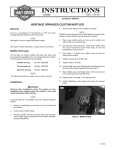
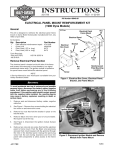
INSTRUCTIONS
®
-J01234
REV. 4-30-98
Kit Number 57912-98 (hardware kit)
STREET STALKER REAR FENDER ASSEMBLY
General
2.
Use rivets (27) and washers (12) to mount circuit
breaker clip (31) to rear fender extension (33).
The following instruction explains mounting the Street Stalker
Rear Fender Assembly. See Service Parts for kit contents.
3.
Install rear fender extension using hardware saved from
step 6 under Stripping Motorcycle.
NOTE
A Service Manual for your motorcycle is available from your
Harley-Davidson Dealer.
4.
Carefully place rear fender in position between fender
supports on frame. The easiest way to do this is to
begin by placing the front of the fender in position with
the fender vertical, then gently squeeze the sides of the
fender, and carefully lower the rear of the fender into
position. Once the fender is in position it can be held in
place as desired by temporarily putting some of the kit
fasteners through the fender and fender support holes.
1WARNING
Read this entire instruction sheet before beginning. Rider
safety depends on the correct installation of this kit.
Follow the procedures in the appropriate Service Manual
when directed to do so. If any procedures are not within
your capabilities, or you do not have the correct tools,
have your Harley-Davidson Dealer perform the installation.
Improper installation could result in personal injury.
Installation
Stripping Motorcycle
1WARNING
To avoid accidental start-up of motorcycle, and possible
personal injury, disconnect the battery cables (negative
cable first) before performing any of the following procedures. If the positive cable should contact ground
with the negative cable installed, the resulting sparks
may cause a battery explosion resulting in personal
injury.
1.
Remove the seat and disconnect battery cables, negative
cable first.
2.
Remove saddlebags, if equipped.
3.
Disconnect the brake light/turn signal wiring harness
connector under the seat.
4.
Remove electrical box cover (containing circuit breakers
and starter relay). Later in these instructions, procedures
will be provided to mount the circuit breakers on the new
rear fender, and mount the starter relay on the frame
adjacent to the ignition module.
5.
Remove the hardware securing the rear fender to the
frame’s fender supports, then remove the fender, fender
support covers, and turn signals as a complete assembly.
6.
Remove the main circuit breaker from its holder on the
lower plastic fender extension, then remove the fender
extension from the motorcycle. Save the hardware to
remount the fender extension included in this kit.
Installing Rear Fender Assembly
(see Figure 2 for items called out below, unless
otherwise noted)
1.
Remove rear footpegs and plug frame holes with hole
plugs (4). On models with shotgun exhaust, install lock
nut (25) over footpeg mount.
1WARNING
Please observe this warning when applying the
adhesive in this kit. EYE IRRITANT. BONDS SKIN IN
SECONDS. CONTAINS CYANOACRYLATE ESTER.
Avoid contact with skin and eyes. In case of eye or
mouth contact, hold eyelid or mouth open and flush
with water. Call physician immediately. If fingers
become bonded, soak in warm soapy water. Avoid
prolonged breathing of vapors. Use with adequate
ventilation. KEEP OUT OF THE REACH OF CHILDREN.
1CAUTION
The set-up time for the gasket adhesive provided in this
kit is short, and the adhesive is very strong. Use care
not to apply an excessive amount of adhesive. Using
too much adhesive may cause the adhesive to run and
damage painted surfaces.
5.
Assemble strut covers as follows:
a. See Figure 1. Apply gasket material from kit around
the edge of the strut covers as shown and cut to
length. The inside corners can be carefully notched
to eliminate buckling of outside edge of gasket. Use
one drop of adhesive from kit on inside surface of
strut cover at each of the four locations shown. Do
not try and apply adhesive to the entire length of the
gasket.
i01227
one drop at each corner
one drop at each end
Figure 1. Strut Cover With Gasket Applied
1 of 4
i01210
29
30
IMPORTANT
Side and rear reflectors (34)
are required to meet D.O.T.
visibility regulations
8
29
17
38
24
20
15
6
35
10
16
23
13
18
13
37
4
19
26
11
14
9
7
Circuit
breakers
39,40
34
34
22
3
5
Starter relay
31
33
Ignition module
27
Starter relay mounts to frame with
right side ignition module well nut
12
Figure 2. Rear Fender Assembly Components
(part numbers correspond to Service Parts illustration)
b. Remove screws that attach lenses to rear lamp
assemblies (37).
c. Attach lamps to lamp brackets (20) with small
screws (shown with lamp assemblies (37)).
d. In right side strut cover, install turn signal unit (38)
with screws (10) and washers (15). Shown
assembled in Figure 3.
e. Install lamp/lamp bracket assemblies into strut
covers. The brackets will slide into slots in strut
covers.
-J01234
f.
Secure harness wires at locations shown with
adhesive-backed clips (2) in kit and place brackets
(19) over lamp/lamp bracket assemblies as shown
in Figure 4.
NOTE
When installing strut covers, route wires between fender
supports and fender. See Figures 5 and 6.
6.
Install screws (7,8,9,30), washers (13,14,29) and nuts
(24,26) as shown in Figure 3 to secure fender and strut
covers to fender supports. Be careful not to pinch any
wires. To achieve the best fit, alternately tighten
hardware from side-to-side. Tighten to 21-27 ft-lbs.
2 of 4
7.
8.
Reassemble lenses to rear lamp assemblies.
Install fusebox boot (23) over circuit breakers, then slide
mounting plate (18) into slot on back of circuit breakers.
Mount circuit breakers to rear fender with well nut (11),
washers (16) and screw (6).
9. Remove ignition module mounting screws from well
nuts in frame. Rotate module 180 degrees. Reinstall left
side screw loosely. Reinstall right side screw loosely
with clamp (3) under module. Tighten module mounting
screws. Install starter relay and splash cover (22) on
clamp using small screw (5).
10. Mate connectors. See Figure 4, 5 and 6 for locations of
connectors. The 3-place connectors coming from the
strut covers (three on the right side and one on the left
side) mate with each other. The 8-place connector
coming from the right side mates with the main harness
located near the right side of the battery. Neatly tuck
wiring as shown in Figures 5 and 6.
11. Check function of turn signals and brake light. Also
check function of hazard lights in both Accessory and
i01229
Ignition modes.
12. Install seat using new washers (21) and screws (28)
from kit. Be careful not to pinch any wires.
1WARNING
After installing seat, be sure it is locked in position. If
seat is loose, it could shift position during vehicle
operation and startle the rider, causing loss of control
and personal injury.
13. Install side reflectors (34) at locations shown in Figure
2. Install rear reflector (34) using rear reflector bracket
(39) and rear reflector bracket tape (40), which attaches
reflector bracket to underside of fender.
1WARNING
Failure to install side and rear reflectors will lead to
reduced visibility. This loss of visibility to other
motorists could result in an accident and possible personal injury.
i01211
Right side tail
light connection
(3-place)
Figure 3. Turn Signal Unit Installed
Left side tail light
connection
(3-place)
Black/white/brown connects to right
side tail light connector
Black/white/purple connects to
left side tail light connector
Figure 5.
Connects to license plate light,
see Instruction Sheet -J01235
i01212
Connects to black/white/brown harness
on this right side strut cover
Connects to main harness
i01228
Figure 4. Right Side Strut Cover Assembled
-J01234
Main harness
connector
8-place
Figure 6.
3 of 4
®
Part No. 57912-98
Service Parts
Street Stalker Rear Fender Assembly
24
8
22
Date 4/98
20
7
29
28
15
4
9
6
14
5
23
25
30
13
27
12
31
3
11
16
17
26
1
Item
1
2
3
4
5
6
7
8
9
10
11
12
13
14
15
16
17
18
19
20
21
22
Description
Cable straps (6)
Adhesive-backed clips (3)
Clamp
Hole plugs (2)
Tapping screw
Panhead screw
Hexhead patch screws (2)
Buttonhead screws (2)
Hexhead capscrews (2)
Tapping screws (2)
Well nut
Washers (2)
Washers (4)
Washers (2)
Washers (2)
Washers (2)
Taillamp gaskets (2)
Mounting plate
Lamp mounting brackets (2)
Lamp bracket
Lockwashers (2)
Relay splash cover
2
Part No.
10006
10102
10134
10219
2567
2806
3445
4118
4724
5209
5210
6047
6701
6702
6716
6717
68859-98
68861-98
68862-98
68863-98
7068
71600-93
21
10
Item
23
24
25
26
27
28
29
30
31
32
33
34
35
36
37
38
39
40
19
18
Description
Fusebox boot
Flange locknuts (2)
Locknut
Locknuts (2)
Blind rivets (2)
Buttonhead screws (2)
3/8 chrome washers (4)
Buttonhead screws (2)
Circuit breaker clip
Solo seat (not shown)
Rear fender extension
(not shown)
Reflectors (3) (not shown)
RH strut cover (not shown)
LH strut cover (not shown)
Rear lamps (2) (not shown)
Turn signal module (not shown)
Rear reflector bracket
(not shown)
Rear reflector
bracket tape (not shown)
Part No.
74427-98
7531
7572W
7667
8483
868
94067-90T
94399-92T
9989A
52381-98
not sold
59263-79
not sold
not sold
68858-98
68864-98
59711-98
58581-99
Hardware kit, PN 57912-98, consists of items 1 through 31
above.
-J01234
4 of 4