1
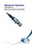
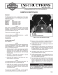
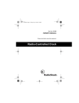
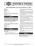
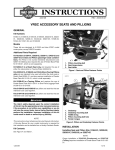
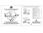
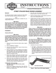
-J05285
REV. 2012-07-03
XL SIGNATURE SERIES SOLO SEAT AND PILLION
GENERAL
Kit Number
52000034 Solo Seat for Custom Tank
NOTE
A service manual for your model motorcycle is available from
a Harley-Davidson dealer.
52000062 Solo Seat for Peanut Tank
Kit Contents
52400053 Passenger Pillion
See Figure 4 and Table 1.
Models
SOLO SEAT ONLY INSTALLATION
For model fitment information, see the P&A Retail Catalog or
the Parts and Accessories section of www.harley-davidson.com
(English only).
Models Equipped With 2-up Seats
1.
Remove the stock seat according to the directions given
in the Owner's Manual. Save the seat mounting screw
(part number 2952A or 3085) to install the new seat.
2.
If you intend to swap back to a 2-up seat and want to keep
the stock rear fender hole location seat retention nut, then
install the second seat retention nut and retention washer
from the seat kit.
Additional Parts Required
For Pillion Kit 52400053 only: On models without passenger
footpegs, install Passenger Footpeg Mount Kit 50203-04.
See Figure 1. If removing the seat retention nut from any fender
hole location, excluding the rear hole location on XL883N,
1200N, 1200X and 1200V models, a fender hole plug, part
number 761, may be desired.
Do not install these seat kits on motorcycles that are not
equipped with an appropriate grab strap and passenger
footpegs. If footpegs and grab strap are not installed,
passenger could fall from moving motorcycle or grab onto
operator, causing loss of control and death or serious
injury. (000410b)
-J05285
a.
See Figure 1. At the middle hole location (3) use the
cable strap (7) from the kit as an installation aid.
b.
Place the retention nut (5) over the cable strap so that
the wide end of the nut rests on the eye of the cable
strap.
c.
Thread the cable strap up under the fender, and
through the fender hole. Pull up on the cable strap to
hold the nut snug against the underside of the fender.
d.
With the rib of the retention nut (5) seated into the
notch in the fender hole, slide the retention washer
(6) into place from the rear. This will lock the retention
nut in place. Remove and discard the cable strap.
Many Harley-Davidson® Parts & Accessories are made of plastics and metals which can be recycled.
Please dispose of materials responsibly.
1 of 6
is07384
7
4
8
3
6
2
1
5
5
1.
2.
3.
4.
6
Rear fender
Two-up seat fender hole
Solo seat mid-fender hole
Solo seat forward fender hole
5.
6.
7.
8.
Seat retention nut
Retention clip
Cable strap
Fender hole plug
Figure 1. Fender Hole Locations
3.
If you do not intend to keep the stock rear fender hole
location seat retention nut, remove the retention washer
and nut from the fender, install the seat retention nut from
the seat kit and fill the rear fender hole with fender hole
plug (part number 761, purchased separately).
a.
To remove the seat retention nut from the rear fender
hole location (2), slide the retention washer (6) from
the groove in the retention nut (5) being sure to catch
the nut as it falls through the fender. Discard both.
b.
At the middle hole location (3) use the cable strap (7)
from the kit as an installation aid.
c.
Place the retention nut (5) over the cable strap so that
the wide end of the nut rests on the eye of the cable
strap.
d.
Thread the cable strap up under the fender, and
through the fender hole. Pull up on the cable strap to
hold the nut snug against the underside of the fender.
e.
With the rib of the retention nut (5) seated into the
notch in the fender hole, slide the retention washer
(6) into place from the rear. This will lock the retention
nut in place. Remove and discard the cable strap.
f.
At the rear fender hole location (2) align the tab on
the hole plug (8) with the notch in the fender hole and
press into place.
-J05285
4.
XL1200X and 1200V models will require the installation
of the seat retention nut in the middle hole location (3) and
can keep the retention nut at the forward hole location (4).
a.
At the middle hole location (3) remove the stock hole
plug and discard.
b.
Use the cable strap (7) from the kit as an installation
aid.
c.
Place the retention nut (5) over the cable strap so that
the wide end of the nut rests on the eye of the cable
strap.
d.
Thread the cable strap up under the fender, and
through the fender hole. Pull up on the cable strap to
hold the nut snug against the underside of the fender.
e.
With the rib of the retention nut (5) seated into the
notch in the fender hole, slide the retention washer
(6) into place from the rear. This will lock the retention
nut in place. Remove and discard the cable strap.
2 of 6
is07363
2
3
4
5
1
6
7
8
1.
2.
3.
4.
5.
6.
7.
8.
Seat tongue
Keyhole
Grabstrap mount hooks
Grabstrap
Rear seat tab location
Pillion front mount tongue
Pillion rear seat tab
Seat tab fasteners
Figure 2. Underside of Seat Assembly
until the seat is firmly in place. Reference the Owner's
Manual for further instruction on seat placement if needed.
NOTE
The foam cushioning of the seat may need to be compressed
as the seat is slid forward to engage the post on the frame.
The front tongue on the underside of the seat should fit snugly
in the groove at the fuel tank rear mounting location. The keyhole on the underside of the seat will lock the seat to the post
on the frame.
1.
See Figure 2. Install seat assembly to the vehicle:
a.
b.
2.
Angle the front of the new seat into place so the
tongue (1) engages the slot at the rear fuel tank
mounting location.
Push the seat forward and rotate the rear of the seat
downward until the seat contacts the frame. Flex the
seat slightly in the middle and slide the seat towards
the rear so that the keyhole slot (2) on the seat bottom
engages with the center seat post on the frame.
3.
See Figure 4. Install the seat mounting screw (L or M)
removed earlier, and fasten the seat mounting bracket (6)
to the middle fender hole location.
4.
Tighten the mounting bracket screw securely to the fender
to 20-40 in-lbs (2.3 - 4.5 Nm).
SOLO SEAT AND PILLION INSTALLATION
Models Equipped With Solo Seats (excluding 883N,
1200N, 1200X and 1200V models):
1.
Remove the stock seat according to the directions given
in the Owner's Manual. Save the seat mounting screw
(part number 2952A or 3085) to install the new seat.
2.
See Figure 1. If you intend to swap back to a solo seat
and want to keep the stock middle fender hole location
Pull up on the center of the seat to verify that it is locked
into place. If the seat is not firmly in place, repeat Step 1
-J05285
3 of 6
seat retention nut, then install the seat retention nut and
retention washer from the seat kit.
a.
If applicable, remove the stock fender hole plug and
discard.
b.
At the rear hole location (2) use the cable strap (7)
from the kit as an installation aid.
c.
Place the retention nut (5) over the cable strap so that
the wide end of the nut rests on the eye of the cable
strap.
d.
Thread the cable strap up under the fender, and
through the fender hole. Pull up on the cable strap to
hold the nut snug against the underside of the fender.
e.
3.
If you do not intend to keep the stock middle fender hole
location seat retention nut, remove the retention washer
and nut from the fender, install the seat retention nut from
the seat kit and fill the middle fender hole with fender hole
plug (part number 761, purchased separately).
a.
At the rear hole location (2) use the cable strap (7)
from the kit as an installation aid.
c.
Place the retention nut (5) over the cable strap so that
the wide end of the nut rests on the eye of the cable
strap.
d.
Thread the cable strap up under the fender, and
through the fender hole. Pull up on the cable strap to
hold the nut snug against the underside of the fender.
f.
With the rib of the retention nut (5) seated into the
notch in the fender hole, slide the retention washer
(6) into place from the rear. This will lock the retention
nut in place. Remove and discard the cable strap.
At the middle fender hole location (3) align the tab on
the hole plug (8) with the notch in the fender hole and
press into place.
XL883N, 1200N, 1200X and 1200V models will require
both the stock solo seat and the rear fender mount screw
(part number 3085) removed.
a.
Remove rear fender mount screw (part number 3085)
and retain for later reinstallation.
b.
IF you do not intend to keep the stock middle or forward fender hole location seat retention nut, remove
the retention washer and nut from the fender, install
the seat retention nut from the seat kit and fill the
fender hole with fender hole plug (part number 761,
purchased separately).
-J05285
•
See Figure 2. Install pillion assembly to the seat assembly:
a.
Remove the rear seat tab (7) and fasteners (8) from
the solo seat assembly and discard.
b.
Insert the pillion front mount tongue (6) into the seat
assembly slot (5) aligning the mount holes.
c.
Insert seat tab fasteners (8) from the pillion kit and
tighten to secure the pillion assembly to the seat
assembly.
d.
d. Torque fasteners to 36-60 in-lbs (4.1 - 6.8 Nm).
NOTES
Visible side of the grabstrap will have no exposed material
edges showing. The seat side of the grabstrap will have
one exposed edge.
•
It may be necessary to use the equivalent of a spoon or
other flat tool to compress the seat foam away from the
underside of the hook to ease engagement of the
grabstrap with the hook.
6.
Install grabstrap to underside of seat assembly:
To remove the seat retention nut from the middle
fender hole location (3), slide the retention washer
(6) from the groove in the retention nut (5) being sure
to catch the nut as it falls through the fender. Discard
both.
b.
e.
4.
With the rib of the retention nut (5) seated into the
notch in the fender hole, slide the retention washer
(6) into place from the rear. This will lock the retention
nut in place. Remove and discard the cable strap.
5.
a.
Place the seat assembly upside-down on a clean,
soft surface with access to the seat mount structure,
oriented with the rear seat tab (7) facing toward you.
b.
Obtain the grabstrap from the pillion kit and place with
the cosmetic side facing down on the surface just
under the rear seat tab, oriented from side to side.
c.
Wrap the grabstrap around the seat assembly, guiding
the grabstrap end toward the structure hooks in the
seat (3).
d.
Place the grabstrap end hole over the hook, entering
the hole through the visible side of the grabstrap.
Feed the grabstrap all the way around the hook until
fully engaged with the hook.
e.
Repeat steps c. and d. above with the other end of
the grabstrap ensuring that the strap is not twisted
when in its final resting position.
NOTE
The foam cushioning of the seat may need to be compressed
as the seat is slid forward to engage the post on the frame.
The front tongue on the underside of the seat should fit snugly
in the groove at the fuel tank rear mounting location. The keyhole on the underside of the seat will lock the seat to the post
on the frame.
7.
8.
Install seat and pillion assembly to the vehicle.
a.
Angle the front of the new seat into place so the
tongue (1) engages the slot at the rear fuel tank
mounting location.
b.
Push the seat forward and rotate the rear of the seat
downward until the seat contacts the frame. Flex the
seat slightly in the middle and slide the seat towards
the rear so that the keyhole slot (2) on the seat bottom
engages with the center seat post on the frame.
Pull up on the center of the seat to verify that it is locked
into place. If the seat is not firmly in place, repeat Step 7
until the seat is firmly in place. Reference the Owner's
Manual for further instruction on seat placement if needed.
4 of 6
NOTE
On XL883N, 1200N, 1200X and 1200V models, place guide
washer (part number 7487) over rear seat mounting hole in
fender before installing seat screw.
9.
See Figure 4. Install the seat mounting screw (L or M)
removed earlier, and fasten the seat mounting bracket (6)
to the rear fender hole location.
10. Tighten the mounting bracket screw securely to the fender
to 20-40 in-lbs (2.3 - 4.5 Nm).
BACKREST INSTALLATION AND
ADJUSTMENT
Installation
1.
2.
Insert backrest assembly, with pad facing forward, into
slot (2) under the flaps.
3.
Insert until retention spring (4) engages tab (3) inside seat
and locks the backrest in place.
Vertical Adjustment
1.
See Figure 4. Lift the flap (E) on the back of the backrest
(2) and expose the spring-pin (4).
2.
Pull the spring pin (4) at the back of the backrest and
adjust the backrest to the desired height.
3.
Release the spring pin and verify that it locks into place
in one of the positioning holes (F).
4.
Secure the backrest flap (E) by re-engaging the hook-andloop.
See Figure 3. Open hook-and-loop flaps (1) on seat
assembly.
is07380
1
5
3
2
4
1.
2.
3.
4.
5.
Seat flaps
Backrest slot
Structure spring tab
Release spring slot
Backrest fore-aft adjustment knob
Figure 3. Backrest
NOTE
Removal
The backrest can be freely folded forward to allow for easier
mounting and dismounting of the motorcycle. Backrest must
afterward be manually returned to an upright position to function.
1.
Fully open the rear-most hook-and-loop flap (A) on seat
to be able to access behind the backrest mount structure.
2.
Press the spring (5) against the backrest mount bracket
until the spring slot (D) disengages spring tab (C).
Forward and Rearward Adjustment
3.
Remove the rider backrest by pulling upward from the
seat.
4.
Secure the flaps (A) by engaging the hook-and-loop.
1.
Adjust the seat flaps (A) to expose the adjustment knob
(3).
2.
Turn the knob clockwise to adjust the backrest forward.
Turn the knob counter-clockwise to adjust the backrest
rearward.
-J05285
5 of 6
SERVICE PARTS
is07383
K
E
F
A
B
J
H
4
C
2
L
3
M
6
D
1
11
5
G
8
12
7
9
10
13
Figure 4. Service Parts
Table 1. Service Parts Table
Item
Description (Quantity)
Part Number
1
Solo seat assembly (includes items 6 and 7, seat kits 52000034 and 52000062)
Not Sold Separately
2
Rider backrest assembly (includes items 3-5, seat kits 52000034 and 52000062)
52000022
3
Adjustment knob
51868-06A
4
Pull pin, height adjustment
Not Sold Separately
5
Engagement/release spring
Not Sold Separately
6
Rear seat/pillion tab
51652-97A
7
Screw, flange head, 1/4-20 x 3/4 lg (2) in
3574
8
Seat retention nut
59768-97
9
Seat retention washer
10
Cable strap
10039
11
Pillion seat assembly (pillion kit 52400053)
Not Sold Separately
12
Grabstrap (pillion kit 52400053)
51680-07
13
Guide washer (pillion kit 52400053)
7487
Items mentioned in text, but not included in kit:
A
Seat slot flaps
B
Backrest slot in seat
C
Backrest spring tab
D
Backrest release spring slot
E
Rider backrest flap
F
Vertical adjustment holes
G
Grabstrap hooks in seat
H
Grabstrap end mount holes
J
Pillion front mount tongue
K
Pillion rear tab mount location
L
Seat screw, truss head, SEMS, 1/4-20 x 1/2 in lg, tooth washer
M
Screw, truss head, SEMS, 1/4-20 x 1/2 in lg, flat washer (XL883N, 1200N, 1200X and 3085
1200V models)
N
Fender hole plug (not shown in figure)
-J05285
2952A
761
6 of 6