1
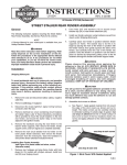
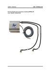
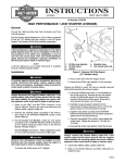
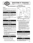
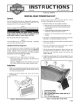
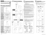
INSTRUCTIONS
®
REV. 8-28-03
-J02179
Kit Number 54631-02B
LOW-PROFILE REAR TOURING SUSPENSION KIT
General
This kit fits 1997 and later Touring model motorcycles. This
kit requires the separate purchase of air pump part
number 54630-03A. This part is available for purchase
from any Harley-Davidson Dealer.
f1446
1WARNING
Installation of any accessory suspension components
may affect cornering clearance. This could distract the
rider, causing loss of control and could result in death
or serious injury.
Air-hose
fitting
1WARNING
The rider’s safety depends on the correct installation of
this kit. Follow the procedures listed in this Instruction
Sheet and applicable Service Manual. If any procedures
are not within your capabilities, or you do not have the
correct tools, have your Harley-Davidson Dealer perform the installation. Improper installation could result
in death or serious injury.
Figure 1. Rear Shock Absorber
Air
hose
i02360
NOTE
A Service Manual for your vehicle is available from any
Harley-Davidson dealer.
Installation
1. Refer to the Service Manual and follow the instructions
given to remove the seat and disconnect the battery
cables, negative cable first.
2. Raise the rear end of the motorcycle so that the rear
wheel is just off the ground. Support the motorcycle with
suitable blocking under the frame.
NOTE
Retain the original fasteners for installation of new shocks.
3. Remove the saddlebags from the motorcycle. See the
Touring model’s Owner’s Manual for saddlebag
removal.
4. Fasten the air pump, part number 54630-03A to the rear
air-suspension adjustment valve on the motorcycle. See
the Touring model’s owner’s manual for valve location.
Add 3-5 psi to clear the line but do NOT exceed 50 psi.
5. Using the pressure-relief valve located below the gauge
on the pump, release the air pressure from the rear suspension.
1CAUTION
Failure to relieve air pressure from the rear suspension
could cause injury during shock-absorber removal.
Air hose
fitting
Plastic
collar
Figure 2. Air Hose Removal and Installation
1WARNING
Use caution when bleeding air from the suspension.
Moisture combined with lubricant may leak on to the
rear wheel, tire, and/or brake components and adversely
affect traction, which could result in death or serious
injury. (00084a)
6. See Figure 1 and Figure 2. Remove the air hoses from
the shock absorber air-hose fittings.
NOTE
Press the plastic collar down on the air-hose fitting to
remove and install the air hose.
7. Remove the air hose fittings from the shock absorbers.
Save the fittings for installation on the new shocks.
NOTE
Air-suspension shock absorbers are oil filled and must be
kept upright at all times to prevent oil leakage.
8. Remove the lower mounting bolts and washers from the
shock absorbers.
-J02179
1 of 2
9. Remove the upper mounting bolts and washers from
the shock absorbers.
10. Apply teflon tape or thread sealant to the air-hose fittings
removed in step 7.
11. Replace the plugs in the new shock absorbers with the
air-hose fittings removed in step 7. Tighten the fittings
until they are snug in the shock absorbers.
12. Install the plugs removed from new shocks (in Step 11)
into old shocks to prevent oil loss.
13. Install the washers removed in step 9 onto the upper
shock bolts and push the bolts through the shock upper
bushings. Apply two or three drops of Loctite 243 (blue)
to the exposed threads of the upper shock-mounting
bolt.
14. Fasten the top of the new shocks to the frame. Tighten
the upper shock bolts to 33 – 35 ft-lbs (45 – 47 Nm).
15. Install the washers removed in step 8 onto the lower
shock bolts and push the bolts through the shock lower
bushings. Apply two or three drops of Loctite ® 243
(blue) to the exposed threads of the lower shock-mounting bolt.
16. Fasten the bottom of the new shocks to the swingarm.
Tighten the lower shock bolts to 35 – 40 ft-lbs (47 –
54 Nm).
17. Fasten the air hoses, removed in step 6, to the air-hose
fittings on the new shocks.
CAUTION
Do not exceed maximum air pressure of 50 psi for low
profile rear suspension. Air components fill rapidly.
Therefore, use low air line pressure. Failure to do so
may result in possible damage to components.(00165a)
®
Service Parts
18. Fasten the shock-absorber air pump to the rear airsuspension adjustment valve. Pressurize the rear airsuspension system to check for air leaks. Adjust air
pressure for rider comfort and to accommodate
changing load conditions. Do not exceed 50 psi
(241kPa).
19. Install the saddlebags.
20. Reconnect negative(-) cable to battery.
1WARNING
After installing seat, pull upward on front of seat to be
sure it is in locked position. While riding, a loose seat
can shift causing loss of control, which could result in
death or serious injury. (00070a)
The following are recommended Starting points; adjust to
suit load conditions, riding style and comfort desired.
NOTE
Less initial pressure does not necessarily result in a softer
ride.
Recommended Pressures-Kit 54631-02B
Shock Loading
Recommended Pressures
Single rider under 160 lbs.
PSI
0-5
kPa
0-34.4
Single rider 160-200 lbs.
0-10
0-68.8
Single rider over 200 lbs.
5-10
34.4-68.8
Two-up
180 lb rider and
120-150 lb passenger
20-30
137.6-206.4
Two-up
180 lb rider and
160 lb passenger
25-35
172-240.8
Two-up and
Fully loaded Bags
40-50
275.2-344
Maximum Pressure
50
344
Part No. 54631-02B
Date 8/03
Low-Profile Suspension Kit
i02359a
Item
1
Description
Low-Profile Shock Absorber
Part No.
54661-02A
1
-J02179
2 of 2