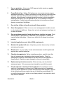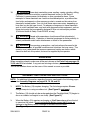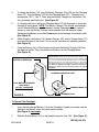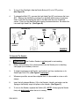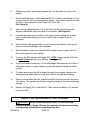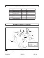
1
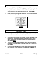
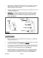
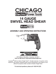
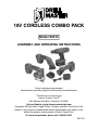
18V CORDLESS COMBO PACK
Model 90374
ASSEMBLY AND OPERATING INSTRUCTIONS
Due to continuing improvements,
actual product may differ slightly from the product described herein.
Distributed exclusively by
Harbor Freight Tools®.
3491 Mission Oaks Blvd., Camarillo, CA 93011
Visit our Web site at: http://www.harborfreight.com
Copyright© 2003 by Harbor Freight Tools®. All rights reserved. No portion of this
manual or any artwork contained herein may be reproduced in any shape or form
without the express written consent of Harbor Freight Tools.
For technical questions, please call 1-800-444-3353.
REV 07l
PRODUCT SPECIFICATIONS
Item
Description
Electrical Requirements
Batter Charger Input: 120 VAC / 60 Hz
Battery Output: 18 VDC
Battery Charging Time
3 to 5 Hours
Drill Specifications
3/8" Keyless / Reversible / Single Speed / 900 RPM
Squeeze Trigger / Torque Adjustments: 1 - 8
Oscillating Sander
Specifications
Triangle Shape / Hook & Loop Attachment
6,000 OPM / Rocker Power Switch
Flashlight Specifications
Pistol Grip / 0 - 90 Degree Swivel Head / Slider Power Switch
Stepped Lens (Clear) / 8 Watt Bulb
Jigsaw Specifications
1/2" Stroke / 1,700 SPM / One Speed / Squeeze Trigger
Safety Lock / Blade Guard / Angle Adjustable
Accessories
Rechargeable 18 VDC Battery / Battery Charger
Weight
13.40 Pounds
SAVE THIS MANUAL
You will need this manual for the safety warnings and precautions, assembly,
operating, inspection, maintenance and cleaning procedures, parts list and assembly diagram. Keep your invoice with this manual. Write the invoice number
on the inside of the front cover. Keep this manual and invoice in a safe and dry
place for future reference.
GENERAL SAFETY RULES
WARNING!
READ AND UNDERSTAND ALL INSTRUCTIONS
Failure to follow all instructions listed below may result in
electric shock, fire, and/or serious injury.
SAVE THESE INSTRUCTIONS
WORK AREA
1.
Keep your work area clean and well lit. Cluttered benches and dark areas
invite accidents.
2.
Do not operate power tools in explosive atmospheres, such as in the
presence of flammable liquids, gases, or dust. Power tools create sparks
which may ignite the dust or fumes.
SKU 90374
PAGE 2
REV 05g, 07l
3.
Keep bystanders, children, and visitors away while operating a power tool.
Distractions can cause you to lose control. Protect others in the work area from
debris such as chips and sparks. Provide barriers or shields as needed.
ELECTRICAL SAFETY
4.
Grounded tools must be plugged into an outlet properly installed and
grounded in accordance with all codes and ordinances. Never remove the
grounding prong or modify the plug in any way. Do not use any adapter
plugs. Check with a qualified electrician if you are in doubt as to whether
the outlet is properly grounded. If the tools should electrically malfunction or
break down, grounding provides a low resistance path to carry electricity away
from the user.
5.
Double insulated tools are equipped with a polarized plug (one blade is
wider than the other). This plug will fit in a polarized outlet only one way. If
the plug does not fit fully in the outlet, reverse the plug. If it still does not
fit, contact a qualified electrician to install a polarized outlet. Do not
change the plug in any way. Double insulation
eliminates the need for the
three wire grounded power cord and grounded power supply system.
6.
Avoid body contact with grounded surfaces such as pipes, radiators,
ranges, and refrigerators. There is an increased risk of electric shock if your
body is grounded.
7.
Do not expose power tools to rain or wet conditions. Water entering a power
tool will increase the risk of electric shock.
8.
Do not abuse the Power Cord. Never use the Power Cord to carry the tools
or pull the Plug from an outlet. Keep the Power Cord away from heat, oil,
sharp edges, or moving parts. Replace damaged Power Cords immediately.
Damaged Power Cords increase the risk of electric shock.
9.
When operating a power tool outside, use an outdoor extension cord
marked “W-A” or “W”. These extension cords are rated for outdoor use, and
reduce the risk of electric shock.
PERSONAL SAFETY
10.
Stay alert. Watch what you are doing, and use common sense when
operating a power tool. Do not use a power tool while tired or under the
influence of drugs, alcohol, or medication. A moment of inattention while
operating power tools may result in serious personal injury.
SKU 90374
PAGE 3
11.
Dress properly. Do not wear loose clothing or jewelry. Contain long hair.
Keep your hair, clothing, and gloves away from moving parts. Loose
clothes, jewelry, or long hair can be caught in moving parts.
12.
Avoid accidental starting. Be sure the Power Switch is off before plugging
in. Carrying power tools with your finger on the Power Switch, or plugging in
power tools with the Power Switch on, invites accidents.
13.
Remove adjusting keys or wrenches before turning the power tool on. A
wrench or a key that is left attached to a rotating part of the power tool may result
in personal injury.
14.
Do not overreach. Keep proper footing and balance at all times. Proper
footing and balance enables better control of the power tool in unexpected
situations.
15.
Use safety equipment. Always wear eye protection. Dust mask, non-skid
safety shoes, hard hat, or hearing protection must be used for appropriate
conditions.
TOOL USE AND CARE
16.
Use clamps (not included) or other practical ways to secure and support
the workpiece to a stable platform. Holding the work by hand or against your
body is unstable and may lead to loss of control.
17.
Do not force the tool. Use the correct tool for your application. The correct
tool will do the job better and safer at the rate for which it is designed.
18.
Do not use the power tool if the Power Switch does not turn it on or off.
Any tool that cannot be controlled with the Power Switch is dangerous and must
be replaced.
19.
Disconnect the Battery from the tool before making any adjustments,
changing accessories, or storing the tool. Such preventive safety measures
reduce the risk of starting the tool accidentally.
20.
Store idle tools out of reach of children and other untrained persons. Tools
are dangerous in the hands of untrained users.
21.
Maintain tools with care. Keep cutting tools sharp and clean. Properly
maintained tools with a sharp cutting edge are less likely to bind and are easier
to control. Do not use a damaged tool. Tag damaged tools “Do not use” until
repaired.
SKU 90374
PAGE 4
REV 03j
22.
Check for misalignment or binding of moving parts, breakage of parts, and
any other condition that may affect the tool’s operation. If damaged, have
the tool serviced before using. Many accidents are caused by poorly maintained tools.
23.
Use only accessories that are recommended by the manufacturer for your
model. Accessories that may be suitable for one tool may become hazardous
when used on another tool.
SERVICE
24.
Tool service must be performed only by qualified repair personnel. Service
or maintenance performed by unqualified personnel could result in a risk of injury.
25.
When servicing a tool, use only identical replacement parts. Follow
instructions in the “Inspection, Maintenance, And Cleaning” section of this
manual. Use of unauthorized parts or failure to follow maintenance instructions
may create a risk of electric shock or injury.
GROUNDING
WARNING!
Improperly connecting the grounding wire can result in the risk of electric shock.
Check with a qualfified electrician if you are in doubt as to whether the outlet is
properly grounded. Do not modify the power cord plug provided with the tool.
Never remove the grounding prong from the plug. Do not use the tool if the power
cord or plug is damaged. If damaged, have it repaired by a service facility before
use. If the plug will not fit the outlet, have a proper outlet installed by a qualified
electrician.
SKU 90374
PAGE 5
REV 03j
DOUBLE INSULATED TOOLS: TOOLS WITH TWO PRONG PLUGS
1.
Tools marked “Double Insulated” do not require grounding. They have a special
double insulation system which satisfies OSHA requirements and complies with
the applicable standards of Underwriters Laboratories, Inc., the Canadian
Standard Association, and the National Electrical Code. (See Figure B.)
2.
Double insulated tools may be used in either of the 120 volt outlets shown in the
following illustration. (See Figure B.)
FIGURE B
EXTENSION CORDS
1.
Grounded tools require a three wire extension cord. Double Insulated tools
can use either a two or three wire extension cord.
2.
As the distance from the supply outlet increases, you must use a heavier gauge
extension cord. Using extension cords with inadequately sized wire causes a
serious drop in voltage, resulting in loss of power and possible tool damage.
(See Figure C, below.)
3.
The smaller the gauge number of the wire, the greater the capacity of the cord.
For example, a 14 gauge cord can carry a higher current than a 16 gauge cord.
(See Figure C.)
4.
If using more than one extension cord to make up the total length, make sure
each cord contains at least the minimum wire size required. (See Figure C.)
SKU 90374
PAGE 6
REV 03j
5.
If you are using one extension cord for more than one tool, add the nameplate
amperes and use the sum to determine the required minimum cord size.
(See Figure C.)
6.
If you are using an extension cord outdoors, make sure it is marked with the
suffix “W-A” (“W” in Canada) to indicate it is acceptable for outdoor use.
7.
Make sure your extension cord is properly wired and in good electrical condition.
Always replace a damaged extension cord or have it repaired by a qualified
electrician before using it.
8.
Protect your extension cords from sharp objects, excessive heat, and damp or
wet areas.
RECOMMENDED MINIMUM WIRE GAUGE FOR EXTENSION CORDS*
(120 VOLT)
NAMEPLATE
AMPERES
(At Full Load)
0 – 2.0
2.1 – 3.4
3.5 – 5.0
5.1 – 7.0
7.1 – 12.0
12.1 – 16.0
16.1 – 20.0
FIGURE C
SKU 90374
EXTENSION CORD LENGTH
25
50
75
Feet
Feet
Feet
18
18
18
18
18
18
18
18
16
18
16
14
18
14
12
14
12
10
12
10
* Based on limiting the line voltage drop
to five volts at 150% of the rated amperes.
PAGE 7
100
Feet
18
16
14
12
10
-
150
Feet
16
14
12
12
-
SYMBOLOGY
Double Insulated
Canadian Standards
Association
Underwriters
Laboratories, Inc.
V~
A
no xxxx/min.
Volts Alternating Current
Amperes
No Load Revolutions
per Minute (RPM)
SPECIFIC SAFETY RULES
1.
Maintain a safe working environment. Keep the work area well lit. Make sure
there is adequate surrounding workspace. Always keep the work area free of
obstructions, grease, oil, trash, and other debris. Do not use the Combo Pack in
areas near flammable chemicals, dusts, and vapors.
2.
Maintain labels and nameplates on the Combo Pack. These carry
important information. If unreadable or missing, contact Harbor Freight Tools for
a replacement.
3.
Ground this product. To comply with the National Electric Code, and to provide
additional protection from the risk of electrical shock, the Battery Charger (1B)
should only be connected to a 120 volt electrical outlet that is protected by a
Ground Fault Circuit Interrupter (GFCI).
4.
When using a hand-held power tool, always maintain a firm grip on the tool
with both hands.
5.
To avoid electrical shock, do not pull or carry the Battery Charger/Charger
Base (1B, 1C) by its Power Cord or pull the Power Cord around sharp
corners or edges. Do not unplug the Battery Charger by pulling on the Power
Cord. Keep the Power Cord away from heated surfaces.
6.
Never leave the Battery Charger (1B) unattended when it is plugged into an
electrical outlet. Make sure to unplug the Battery Charger from its outlet before
leaving.
SKU 90374
PAGE 8
REV 04f
7.
Use eye protection. Always wear ANSI approved safety impact eye goggles
when working with these products.
8.
Proper Battery Care: Battery (1A) leakage may occur under extreme usage or
temperature conditions. If Battery fluid comes in contact with skin, wash with soap
and water and rinse with lemon juice and vinegar. If the fluid comes in contact
with eyes, flush with water for several minutes and contact a doctor immediately.
Never burn the Battery, as it can explode in a fire. Do not attempt to charge a
leaking Battery. Contact local solid waste authorities for instructions on correct
disposal or recycling of the Battery.
9.
Do not allow children to handle or play with these products.
10.
Store idle equipment. When not in use, tools and equipment should be stored
in a dry location to inhibit rust. Always lock up tools and equipment, and keep out
of reach of children.
11.
Do not use these products if under the influence of alcohol or drugs. Read
warning labels on prescriptions to determine if your judgement or reflexes are
impaired while taking drugs. If there is any doubt, do not attempt to use these
products.
12.
Industrial applications must follow OSHA requirements.
13.
Maintain this product with care. Keep these products clean and dry for better
and safer performance.
14.
Maintenance: For your safety, service and maintenance should be performed
regularly by a qualified technician.
15.
Check for damaged parts. Before using these products, carefully check that
they will operate properly and perform their intended function. Check for
damaged parts and any other conditions that may affect the safe operation of
these products. Replace or repair damaged or worn parts immediately.
16.
Replacement parts and accessories: When servicing, use only identical
replacement parts. Only use accessories intended for use with this product.
17.
Use the right tool or attachment for the right job. Do not attempt to force a
small tool or attachment to do the work of a larger industrial tool or attachment.
There are certain applications for which these products were designed. They will
do the job better and more safely at the rate for which they were intended. Do
not modify these products, and do not use these products for a purpose for which
they were not intended.
SKU 90374
PAGE 9
18.
WARNING! Some dust created by power sanding, sawing, grinding, drilling,
and other construction activities, contain chemicals known (to the State of
California) to cause cancer, birth defects or other reproductive harm. Some
examples of these chemicals are: lead from lead-based paints, crystalline silica
from bricks and cement or other masonry products, arsenic and chromium from
chemically treated lumber. Your risk from these exposures varies, depending on
how often you do this type of work. To reduce your exposure to these chemicals:
work in a well ventilated area, and work with approved safety equipment, such as
those dust masks that are specially designed to filter out microscopic particles.
(California Health & Safety Code 25249.5, et seq.)
19.
WARNING! People with pacemakers should consult their physician(s)
before using this product. Operation of electrical equipment in close proximity to
a heart pacemaker could cause interference or failure of the pacemaker.
20.
WARNING! The warnings, precautions, and instructions discussed in this
manual cannot cover all possible conditions and situations that may occur. The
operator must understand that common sense and caution are factors which
cannot be built into this product, but must be supplied by the operator.
UNPACKING
When unpacking, check to make sure all the parts shown on the Parts Lists on pages 18,
19, 20, and 21 are included. If any parts are missing or broken, please call Harbor Freight
Tools at the number shown on the cover of this manual as soon as possible.
ASSEMBLY AND OPERATING INSTRUCTIONS
NOTE: For additional information regarding the parts mentioned in the following pages,
refer to the Assembly Diagrams on pages 18, 19, 20, and 22.
1.
NOTE: The Battery (1A) requires charging. The first charge requires 5 hours
charge time prior to using a cordless tool. (See Figure D, next page.)
2.
The Battery (1A) should only be re-charged when the Flashlight Bulb (7C) begins to
dim or a cordless tool begins to run slowly. (See Figure D.)
3.
When the Battery (1A) requires re-charging, a 3 to 5 hour charge allows the tool
to operate at full power. Do not re-charge the Battery longer than 5 hours, as
damage to the Battery and/or Flashlight or cordless tool will occur.
(See Figure D.)
SKU 90374
PAGE 10
4.
To charge the Battery (1A), plug the Battery Charger’s Plug (1B) into the Charging
Base (1C). Plug the Battery (1A) into the Charging Base (1C). Charging room
temperature: 50° F - 104° F. Then, plug the Battery Charger into the nearest 120
Volt, grounded, electrical outlet. (See Figure D).
5.
A Charging Indicator Light on the Charging Base (1C) will illuminate to show that
charging is taking place. NOTE: The Battery Charger (1B) will not automatically
turn off when the Battery is fully charged, and the Charging Indicator Light will
remain on until the Battery Charger is disconnected from the electrical outlet.
Recharging the Battery more than 5 hours can cause damage to the battery cells.
(See Figure D.)
6.
While charging, the Battery (1A), Battery Charger (1B), and/or Charger Base (1C)
may become warm to the touch. This is normal, and does not indicate a problem.
(See Figure D.)
7.
Once the Battery (1A) is fully charged, disconnect the Battery Charger (1B) from
the electrical outlet. Then, disconnect the Battery from the Charging Base.
(See Figure D.)
BATTERY CHARGER (1B)
Note: Always switch to a fresh battery when tool performance
begins to diminish. Severe heat is most destructive to a battery; the
more heat generated, the faster the battery loses power. A battery that
gets too hot can be permanently damaged. Never over-discharge a
battery by using the tool even after tool performance is decreasing.
Never attempt to discharge a tool’s battery by continuing to pull the tool
trigger. When tool performance begins to diminish, stop the tool,
re-charge the battery and use the fresh battery for optimal
performance.
CHARGING INDICATOR LIGHT
PLUG BATTERY CHARGER
ONLY INTO A
120 VOLT, GROUNDED,
ELECTRICAL OUTLET.
CHARGING BASE (1C)
CHARGER PLUG
FIGURE D
To Operate The Flashlight:
1.
Insert the fully charged Battery (1A) in the Flashlight’s Handle, and make sure the
Spring on the Battery snaps into place on the Handle.
(See Figure E, next page.)
2.
Slide the Switch Button (4C) on the Handle forward to turn “ON”. (See Figure E.)
SKU 90374
PAGE 11
REV 03j, 04f, 07k
3.
To turn off the Flashlight, slide the Switch Button (4C) to its OFF position.
(See Figure E.)
4.
To change the Bulb (7C), unscrew the Light Head Cap (9C) and remove the Lens
(8C). Remove the old Bulb by pushing in on the Bulb while turning it clockwise.
Insert a new Bulb by aligning the tabs on the Bulb with the slots in the Bulb
socket. Push in on the new Bulb while turning it counterclockwise. Re-attach the
Lens and Light Head Cap. (See Figure E.)
BATTERY (1A)
FLASHLIGHT
HANDLE
LIGHT
HEAD
CAP
(9C)
SWITCH
BUTTON
(4C)
LENS
(8C)
BULB
(7C)
FIGURE E
To Operate The Sander:
1.
WARNING! The Cordless Sander is not designed for wet sanding.
2.
Make sure the Battery (1A) is disconnected from the Sander prior to attaching
sand paper (not included) to the tool.
3.
To attach sand paper to the Sander, use the hook and loop mechanism on its
Sand Paper Pad (17D). (See Figure F, next page.)
4.
Whenever possible, secure the workpiece that is to be sanded in a vise or with
clamps.
5.
Insert the fully charged Battery (1A) in the Sander’s Handle, and make sure the
Spring on the Battery snaps into place on the Handle. (See Figure F.)
6.
To turn on the Sander, squeeze the Switch (3D). NOTE: Always grip the Sander
firmly with both hands when the tool is running.
SKU 90374
PAGE 12
7.
Lightly apply the oscillating Sand Paper Pad (17D) to the workpiece surface, and
begin sanding the workpiece by moving the tool forward and backward with
(parallel to) the grain of the workpiece.
8.
Once the sanding job is completed, release pressure on the Switch (3D) to turn off
the Sander. (See Figure F.)
9.
IMPORTANT: If, during the sanding process it becomes necessary to replace
worn sand paper with new sand paper, make sure to turn off the Sander and
disonnect the Battery (1A). Re-install new sand paper and then re-attach the
Battery. (See Figure F.)
SAND PAPER
PAD
(17D)
SANDER
HANDLE
SWITCH
(3D)
SANDER HANDLE
BATTERY (1A)
BATTERY (1A)
FIGURE F
To Operate The Jigsaw:
1.
Make sure the Battery (1A) is disconnected from the Jigsaw prior to attaching the
Saw Blade (16E) to the tool.
2.
To attach the Saw Blade (16E) to the Jigsaw, use the Hex Key (24E) to loosen the
two Hex Socket Screws (14E). (See Figure G, next page.)
3.
Insert the shank of the Saw Blade (16E) upward into the Blade Holder (15E) with
its saw teeth pointing to the front of the tool. Then, re-tighten the two Hex Socket
Screws (14E) to secure the Saw Blade in place. (See Figure G.)
4.
If desired, the angle of a cut may be adjusted. To do so, loosen the Hex Socket
Screw (14E) located on the underside of the Sander. Tilt the Base Plate (19) to
the desired angle. Then, re-tighten the Hex Socket Screw. (See Figure G.)
SKU 90374
PAGE 13
5.
Whenever possible, secure the workpiece that is to be cut in a vise or with
clamps.
6.
Insert the fully charged Battery (1A) in the Jigsaw’s Handle, and make sure the
Spring on the Battery snaps into place on the Handle.
(See Figure G.)
7.
The Jigsaw is equipped with a Safety Button that prevents accidental starting. To
turn on the Jigsaw, depress the Safety Button and then squeeze the Switch (5E).
NOTE: Always grip the Jigsaw firmly with both hands when the tool is running.
(See Figure G.)
8.
WARNING! Always keep hands and fingers away from the moving Saw
Blade (16E). (See Figure G.)
9.
Lightly feed the Saw Blade (16E) into the workpiece and apply light, gradual,
forward, pressure on the Jigsaw to move the tool along the area to be cut.
10.
Do not attempt to back out of an uncompleted cut while the Jigsaw is running. If
necessary, release pressure on the Switch (5E) to turn off the Jigsaw. Then,
remove the tool from the workpiece. (See Figure G.)
11.
IMPORTANT: If, during the cutting process it becomes necessary to replace a
bent or broken Saw Blade (16E) with a new Saw Blade, or re-adjust the angle of
the Base Plate (19E), make sure to turn off the Jigsaw and disonnect the Battery
(1A). Re-install a new Saw Blade, or re-adjust the Base Plate, and then re-attach
the Battery. (See Figure G.)
HEX KEY
(24E)
HEX
SOCKET
SCREW
(14E)
HEX
SOCKET
SCREW
(14E)
SAW
BLADE
(16E)
HEX KEY
(24E)
HANDLE
BASE
PLATE
(19E)
FIGURE G
SKU 90374
PAGE 14
BATTERY
(1A)
SAFETY
BUTTON
SWITCH
(5E)
To Operate The Drill:
1.
WARNING! Always make sure the Trigger (3F) of the Cordless Drill is in its
“OFF” position, the Battery (1A) is removed from the Drill, and the Battery
Charger (1B) is unplugged from its electrical outlet prior to making any
adjustments to the tool. (See Figure H.)
2.
The Chuck (12F): Accepts up to 3/8” diameter drill bits (not included) and the
Screwdriver Bit (31F). To install a drill bit, hold the Chuck Sleeve firmly in place
and turn the Chuck (12F) counterclockwise. Insert the shank of a drill bit all the
way into the Chuck. While holding the Chuck Sleeve in place, turn the Chuck
clockwise to lock the drill bit in place. (See Figure H.)
3.
The Trigger (3F): The Trigger is operated manually simply by squeezing the
Trigger to turn on the Drill and releasing pressure on the Trigger to turn off the
Drill. (See Figure H.)
4.
The Rotation Button (33F): The Rotation Button allows you to change the
rotational direction of the Drill. For a clockwise rotation, move the Rotation
Button to the right. For a counterclockwise rotation, move the Rotation
Button to the left. (See Figure H.)
5.
The Torque Setting Ring (8F): The Torque Setting Ring allows you to select
up to eight different driving torque settings, depending on the job required. To
change the driving torque, simply turn the Torque Setting Ring to the desired setting.
(See Figure D.)
TORQUE SETTING RING (8F)
CHUCK SLEEVE
CHUCK (12F)
ROTATION BUTTON (33F)
DRILL HANDLE
TRIGGER (3F)
BATTERY (1A)
FIGURE H
SKU 90374
PAGE 15
6.
Whenever possible, secure the workpiece that is to be drilled in a vise or with
clamps.
7.
When installing drill bits or the Screwdriver Bit (31F), make sure the Battery (1A) is
removed from the Drill to avoid accidental starting. Then, insert and lock in p l a c e
a drill bit or Screwdriver Bit in the Chuck (12F) of the Drill.
(See Figure H.)
8.
Insert the fully charged Battery (1A) in the Drill’s Handle, and make sure the
Spring on the Battery snaps into place on the Handle. (See Figure H.)
9.
Lubricate the cutting tip of the drill bit with cutting oil when drilling iron or steel.
Use a coolant when drilling non-ferrous metals such as copper, brass, or
aluminum.
10.
When drilling in light gauge metal or wood, use a wooden block to back up the
material to prevent damage to the workpiece.
11.
Mark the center of the hole to be drilled with a center punch to give a drill bit a
start and to prevent it from “walking”.
12.
To turn on the Drill, squeeze the Trigger (3F). NOTE: Always grip the Drill firmly
with both hands when the tool is running. (See Figure H.)
13.
Drill only as deep as necessary. Do not drill deeper than necessary into walls or
other areas where you cannot identify any possible hazards behind the drilling
surface.
14.
To reduce jamming as the drill bit breaks through the workpiece, decrease the
drilling pressure when the point of the drill bit breaks through the workpiece.
15.
When you have drilled the hole, remove the drill bit from the hole while the Drill is
still running. This prevents the drill bit from getting caught in the hole and causing
damage.
16.
Release the Trigger (3F) to stop the Drill. Then, remove the Battery (1A) and drill
bit from the Drill.
INSPECTION, MAINTENANCE, AND CLEANING
1.
WARNING! Always remove the Battery Pack (1A) from a tool and
unplug the Battery Charger (1B) from its electrical outlet before performing
any inspection, maintenance, or cleaning on the tool.
SKU 90374
PAGE 16
2.
BEFORE EACH USE, inspect the general condition of the tools. Check for
misalignment or binding of moving parts, cracked or broken parts, damaged
wiring, and any other condition that may affect their safe operation. If abnormal
noise or vibration occurs with a tool, have the problem corrected before further
use. Do not use damaged equipment.
3.
TO CLEAN, use a clean, damp, cloth to clean the outer surfaces of the Combo
Pack tools and accessories. A mild detergent may be used. Do not use solvents.
Do not immerse any of the tools, Battery, or Battery Charger in water.
4.
WHEN STORING, always keep the Combo Pack tools and accessories in a clean,
dry location.
PLEASE READ THE FOLLOWING CAREFULLY
THE MANUFACTURER AND/OR DISTRIBUTOR HAS PROVIDED THE PARTS LIST AND ASSEMBLY
DIAGRAM IN THIS MANUAL AS A REFERENCE TOOL ONLY. NEITHER THE MANUFACTURER OR
DISTRIBUTOR MAKES ANY REPRESENTATION OR WARRANTY OF ANY KIND TO THE BUYER THAT HE
OR SHE IS QUALIFIED TO MAKE ANY REPAIRS TO THE PRODUCT, OR THAT HE OR SHE IS QUALIFIED
TO REPLACE ANY PARTS OF THE PRODUCT. IN FACT, THE MANUFACTUER AND/OR DISTRIBUTOR
EXPRESSLY STATES THAT ALL REPAIRS AND PARTS REPLACEMENTS SHOULD BE UNDERTAKEN BY
CERTIFIED AND LICENSED TECHNICIANS, AND NOT BY THE BUYER. THE BUYER ASSUMES ALL
RISK AND LIABILITY ARISING OUT OF HIS OR HER REPAIRS TO THE ORIGINAL PRODUCT OR
REPLACEMENT PARTS THERETO, OR ARISING OUT OF HIS OR HER INSTALLATION OF REPLACEMENT
PARTS THERETO.
SKU 90374
PAGE 17
REV 07l
PARTS LIST - FLASHLIGHT
Part #
Description
Part #
Description
1A
Batter y
6C
Locate Spring
1B
Batter y Charger
7C
Bulb
1C
Charger Base
8C
Lens
2C
Right Enclosure
9C
Light Head Cap
3C
Switch
10C
Left Enclosure
4C
Switch Button
11C
Screw
5C
Light Head Cover
ASSEMBLY DIAGRAM - FLASHLIGHT
5C
6C
11C
4C
3C
10C
7C
8C
9C
2C
1B
Note: 1C Charger Base
not shown
(see page 11, Figure D)
1A
NOTE: Some parts are listed and shown for illustration purposes only, and are not available individually
as original or replacement parts.
SKU 90374
PAGE 18
REV 04g
PARTS LIST - SANDER
Part #
Description
Part #
Description
1A
Batter y
9D
Gear
1B
Batter y Charger
10D
Bearning
1C
Charger Base
11D
Shaft
1D
Enclosure
12D
Oscillator
2D
Enclosure
13D
Bearing
3D
Switch
14D
Suppor t
4D
Pole Plate
15D
Base Plate
6D
Motor
16D
Tapping Screw
7D
Gear
17D
Sand Paper Pad
8D
Bearing
18D
Tapping Screw
ASSEMBLY DIAGRAM - SANDER
2D
3D
1D
4D
18D
6D 7D
8D
9D
10D
11D
14D
Note: 1C
Charger Base
not shown
12D
1A
1B
15D
13D
17D
16D
NOTE: Some parts are listed and shown for illustration purposes only, and are not available individually
as original or replacement parts.
SKU 90374
PAGE 19
REV 04g
PARTS LIST - JIGSAW
Part #
Description
Part #
Description
1A
Battery
12E
Slide Bar
1B
Battery Charger
13E
Screw
1C
Charger Base
14E
Hex Socket Screw
1E
Enclosure
15E
Blade Holder
2E
Guard
16E
Saw Blade
4E
Pole Plate
17E
Slide Sleeve
5E
Switch
18E
Block
6E
Excentral Gear
19E
Base Plate
7E
Suppor t Bracket
20E
Roller Suppor t
8E
Motor
21E
Spring Washer
9E
Enclosure
22E
Washer
10E
Tapping Screw
23E
Nut
11E
Self-Oiled Bearing
24E
Hex Key
ASSEMBLY DIAGRAM - JIGSAW
1A
2E
9E
8E
4E
7E
10E
1E
5E
18E
6E 11E
12E
21E
Note: 1C
Charger Base
not shown
13E
1B
22E
15E
16E
23E
19E
17E
14E
14E
20E
24E
NOTE: Some parts are listed and shown for illustration purposes only, and are not available individually
as original or replacement parts.
SKU 90374
PAGE 20
REV 04g
PARTS LIST - DRILL
Part #
Description
Part #
Description
1A
Batter y
17F
Small Ball Bearings
1B
Batter y Charger
18F
Governor Box
1C
Charging Base
19F
Shaft Coat
1F
Self Tapping Screw
20F
Spindle
2F
Right Enclosure
21F
Gear Ring
3F
Trigger Switch Assy.
22F
Planetar y Gear
5F
Ring
23F
Planetar y Bracket
6F
Spring
24F
Planetar y Gear
7F
Inner Threaded Ring
25F
Washer
8F
Torque Setting Ring
26F
Self Tapping Screw
9F
Torque Positioning Spring
27F
Motor Flange
10F
Spring Holder
28F
Self Tapping Screw
11F
Self Tapping Screw
29F
Motor
12F
Chuck
30F
Left Enclosure
13F
Chuck Screw
31F
Screwdriver Bit
14F
Ball Bearings
32F
Bit Clip
15F
Fixing Ring
33F
Rotation Button
16F
Small Ring
NOTE: Some parts are listed and shown for illustration purposes only, and are not available individually
as original or replacement parts.
SKU 90374
PAGE 21
REV 04f
ASSEMBLY DIAGRAM - DRILL
32F
31F
30F
33F
29F
2F
28F
27F
1F
26F
25F
24F
21F
3F
20F
23F
22F
19F
18F
17F
16F
15F
14F
1B
5F 6F
1A
7F
8F
1C
9F
10F 11F
12F
13F
NOTE: Some parts are listed and shown for illustration purposes only, and are not available individually
as original or replacement parts.
SKU 90374
PAGE 22
REV 04f