1
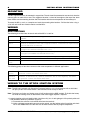
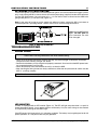
MSD MC-3 MOTORCYCLE IGNITION
PN 4223
The MSD MC-3 Ignition can be used on 1, 2 or 4-cylinder engines using one or two coils. The MC-3 will operate
with conventional points or from the amplifier of an electronic breakerless system. Capacitive discharge (CDI)
units cannot trigger the MSD.
WARNING: During installation, always disconnect the battery cables. When disconnecting the battery, always
remove the Negative cable first and install it last.
Note: The MSD MC-3 will not work with capacitive discharge (CDI) motorcycles.
Parts Included
1 - MSD MC-3 Ignition Control Unit
1 - Motorcycle Cable Assembly
6 - RPM Modules (5,000, 7,000, 9,000, 10,000, 11,000, 12,000 rpm)
1 - Parts Bag
Note: It is recommended that you have the Service Manual for your motorcycle for the installation.
TECH TIPS
The following are technical tips that will help you get the most out of your MSD MC-3 Ignition.
Battery: The battery is a very important component of your ignition system. The battery should be rated at no
less than 10 amp/hours whether you have a charging system or not. If you do not have a charging system,
allow at least 10 amp/hours per each half hour of use. Never start or run the engine while a battery charger is
connected. Some chargers can produce voltage spikes that may damage the ignition components.
Coils: The MSD MC-3 will work with factory and most aftermarket coils. Better spark energy is received at the
plug if lower resistance coils are used (1.5 ohm). However for maximum ignition output, an MSD Motorcycle
Coil, PN 8204 is recommended. The MSD coil is designed specifically for use with the MC-3 Ignition. It has
less resistance and a high turns ratio to match the full capability of the MC-3.
WARNING: Do not touch or connect any test equipment, accessories, etc. to the coil terminals.
Spark Plugs: The increased spark energy of the MC-3 allows you to run a wider spark plug gap (.045"-.060").
The result is more predictable ignition and improved performance.
Spark Plug Wires: Only magnetic suppression wires should be used with the MC-3 Ignition. Magnetic
suppression wires, such as the MSD Heli-Core or Super Conductor wires, suppress electro magnetic interference
(EMI) that is emitted. If not suppressed, this EMI noise may interfere with any electronic components on the
motorcycle. DO NOT use Solid Core wires.
CYLINDER SELECT
The MC-3 is programmed at the factory for 4-cylinder, four stroke or 2-cylinder, and one 1-cylinder two stroke
engines. To program the unit for different applications, see the chart in Figure 1.
CYLINDER
1
2
4
FOUR STROKE
CUT LOOP
CUT LOOP
NO MODIFICATIONS
TWO STROKE
NO MODIFICATIONS
NO MODIFICATIONS
-----
Figure 1 Cylinder Select Wire Loop.
AUTOTRONIC CONTROLS CORPORATION • 12120 ESTHER LAMA, SUITE 114, EL PASO
PASO,, TEXAS 79936 • (915) 857-5200 • FAX (915) 85
8588 -9241
2
INSTALL ATION INSTRUCTIONS
MOUNTING
The MC-3 Ignition Unit may be mounted in any position. The unit should be mounted at least one inch from the
exhaust pipes to avoid excess heat. The suggested location is ahead of the engine at the top of the down
tubes. Make sure the mounting location does not interfere with the normal operation of the motorcycle.
To mount the MC-3, use it as a template and mark the mounting hole locations. Drill the four holes using a
3/16" drill and install four vibration mounts and the MC-3.
WIRING
WIRE FUNCTIONS
The following chart describes what each wire of the MC-3 is used for.
RED
BLACK
GRAY
WHITE
Connects directly to the battery positive (+) terminal or starter solenoid 12 volt
terminal.
Connects to the battery negative (-) terminal or the engine ground.
Connects to switched 12 volt side of ignition switch. It switches the input voltage
from the RED wire on and off.
Connects to the "COIL A" trigger wire from the points or electronic amplifier
(triggers the PURPLE and BLACK wire coil).
GREEN
Connects to the "B COIL" trigger wire from the points or electronic amplifier
(triggers the ORANGE and YELLOW wired coil).
BROWN
LIGHT BLUE
SHORT BLUE
LOOP
Shift Interrupt wire interrupts the ignition output when applied to ground.
Activates the low rpm module when connected to ground.
Cylinder select wire loop.
The following groups of two wires connect to the same components in different applications.
PURPLE
BLACK
Connects to the front coil, "COIL A" terminals. One to coil negative, the other to
positive. It does not matter which wire.
ORANGE
YELLOW
Connects to the back coil, "COIL B" terminals. One to coil negative, the other
to positive. It does not matter which wire.
WIRING TO THE STOCK IGNITION SYSTEM
Note: The MC-3 will not work with Capacitive Discharge Ignitions or 4-cylinder engines with an individual
coil per cylinder. The Yamaha V-Max is one bike that cannot accept an MC-3.
Note: The factory rev limiter and timing curve will still function with the MSD installed. To disable the factory
rev limiter and timing curve an aftermarket stand alone trigger amplifier is required.
1. Locate the ignition coils and identify which side of the coil(s) has 12 volts going to it. If the polarity of the coil
is not identified, follow this procedure (Figure 2):
A. Disconnect the coil wires and remove them from the terminals.
B. Using a voltmeter connected to one wire and to ground, turn the ignition to the On position and check
for 12 volts. Note: Make sure the wires do not make contact with any engine components.
AUTOTRONIC CONTROLS CORPORATION • 12120 ESTHER LAMA, SUITE 114,
EL PASO
PASO,, TEXAS 79936 • (915) 857-5200 • FAX (915) 85
8588 -9241
INSTALLATION INSTRUCTIONS
3
C. The wire that shows 12 volts is the positive side. Turn the ignition Off
and mark that coil wire as positive and the other as negative. If
necessary, mark which wires go to Coil A and Coil B.
NOTE: DISCONNECT
WIRE FROM COIL
BEFORE CHECKING
FOR 12 VOLTS.
Note: If 12 volts is not present on either coil wire the motorcycle may have
a Capacitive Discharge Ignition and cannot use an MSD MC-3.
2. At this point, all of the coil wires should be marked with its polarity and
which coil (A or B) the wires connect to.
Single Coil: Attach the coil’s negative wire to the White wire of the MSD
(Figure 3).
Dual Coils: Attach the Coil A negative wire to the White wire of the MSD
and the Coil B negative wire to the Green wire of the MSD
(Figure 4).
3. Connect the MSD Gray wires to the coil(s) positive wires.
Figure 2 Checking for Coil
Wire Polarity.
Note: The MSD has two Gray wires and it doesn’t
matter which wire(s) connect to which coil in dual
coil applications. For single coil installation,
connect both Gray wires to the original coil
positive wire. These wires provide a switched 12
volt source to turn the MSD on and off.
4. The following wires connect directly to the coil
terminals. The MSD Black and Purple wires
connect to Coil A. The Orange and Yellow wires
attach to Coil B. It does not matter which side of
the coil the wires connect to. If you only have a
single coil, seal the ends of the Orange and Yellow
wires.
5. Review your wiring with Figure 3 or 4 and
make any corrections. If everything matches,
connect the heavy Red wire to the battery
positive (+) terminal and the heavy Black wire to
the negative (-) battery terminal.
The wiring is complete.
Figure 3 Wiring to a Stock Single Coil System.
Figure 4 Wiring to a Stock Dual Coil Ignition System.
AUTOTRONIC CONTROLS CORPORATION • 12120 ESTHER LAMA, SUITE 114,
EL PASO
PASO,, TEXAS 79936 • (915) 857-5200 • FAX (915) 85
8588 -9241
4
INSTALL ATION INSTRUCTIONS
AFTERMARKET AMPLIFIER TRIGGER
By using an aftermarket trigger system on some bikes, the factory timing curve and rev limit may be bypassed.
Use the same wiring procedure as described in the Wiring to a Stock Ignition section. Figures 5 and 6 show
a typical aftermarket amplifier trigger.
Figure 5 Typical Aftermarket Amplifier Trigger without MC-3.
Figure 6 Wiring the MC-3 to an Aftermarket Amplifier Trigger.
INITIAL START-UP
Before starting the engine, review the wiring steps and make sure all of your connections are tight and
secure. Make sure the spark plug wires are installed and the battery terminals are tight then start the
engine.
If the engine runs a short time then stalls, the engine may be equipped with an electric fuel pump relay and
might require an MSD Tach Adaptor, PN 8920. Contact MSD for information. After wiring the MC-3, take time
to review these steps.
• The only wires on the coils should be the PURPLE-BLACK and ORANGE-YELLOW wires. DO NOT
hook any other wires to the coils.
• The GRAY wires should be connected to a switched 12 volt source, allowing the system to be turned
on and off by the ignition switch.
AUTOTRONIC CONTROLS CORPORATION • 12120 ESTHER LAMA, SUITE 114,
EL PASO
PASO,, TEXAS 79936 • (915) 857-5200 • FAX (915) 85
8588 -9241
INSTALLATION INSTRUCTIONS
5
TACH ADAPTER INSTALLATION
If the engine started then stalled within a couple of minutes, you will have to install an MSD Tach Adapter,
PN 8920. The cause for this is due to the fuel pump not receiving a strong enough trigger signal through
the MSD. The Tach Adapter ensures that the fuel pump receives a strong trigger signal (Figure 7).
Figure 7 Installing an MSD Tach Adapter.
TACHOMETER OUTPUT
The MC-3 Ignition has a built-in tach output terminal (Figure 8). This terminal will directly drive
many models of tachs. The output combines both input signals from either the points or electronic
ignition amplifier into one signal. Due to this, it is possible for some tachs to read double the engine
rpm. If the rpm reading is doubled when using the tach output terminal, splice the tach wire into
either the WHITE or the single GREEN wire.
SHIFT LIGHT
A Shift Light can easily be connected to the MC-3. Figure 8 shows a common setup with an MSD
Shift Light.
Figure 8 Wiring an MSD Shift Light.
AUTOTRONIC CONTROLS CORPORATION • 12120 ESTHER LAMA, SUITE 114,
EL PASO
PASO,, TEXAS 79936 • (915) 857-5200 • FAX (915) 85
8588 -9241
6
INSTALL ATION INSTRUCTIONS
PROGRAMMING
SHIFT “INTERRUPT” FEATURE
The MC-3 Ignition has a special Shift "Interrupt"
feature. When applied, the ignition output will be
interrupted thereby unloading the transmission and
allowing the shift to occur. This system is different
than normal ignition “kills” which simply interrupt the
power to the coils causing a spark to occur at the
time the switch is released which may result in severe
backfires.
The MC-3 Interrupt feature only operates in the output
section of the ignition, allowing all of the timing
functions to keep operating properly. This ensures
that no backfires will occur.
Figure 10 Wiring the Air Shift Interrupt Feature.
To incorporate the Interrupt feature, connect the
BROWN wire of the MC-3 to the Normally Open (NO)
terminal of the Shift “Kill” switch. Wire the common
(C) terminal of the switch to ground (Figure 10).
THE TWO STEP MODULE
The Two Step feature of the MC-3 provides the
capability of switching between two rpm limits
that are set using plug-in modules.
To use the Two Step feature, connect the LIGHT
BLUE wire to a switched ground (see Figure 11).
When the LIGHT BLUE wire is grounded, the Low
module is engaged. When the LIGHT BLUE wire
is not grounded (open), the High module is
engaged. Choose the rpm module you wish to
set at low rpm and insert it in the "LOW" module
holder. Insert the high rpm module, for over-rev
protection, in the "HIGH' holder.
Figure 11 Wiring the Two Step Module Selector.
MSD offers additional rpm modules in sets of five, or an adjustable module selector. The module selector
is an adjustable knob that provides several rpm settings for even easier adjustment. The module kits
come in increments of 200 rpm within a range of 1,000 rpm.
PN
RPM
8743
87431
8744
87441
8745
87451
8746
87461
8747
87471
8748
3000
3100
4000
4100
5000
5100
6000
6100
7000
7100
8000
3200
3300
4200
4300
5200
5300
6200
6300
7200
7300
8200
3400
3500
4400
4500
5400
5500
6400
6500
7400
7500
8400
3600
3700
4600
4700
5600
5700
6600
6700
7600
7700
8600
3800
3900
4800
4900
5800
5900
6800
6900
7800
7900
8800
87481 8100
8300
8500
8700
8900
PN
8670
8671
8672
RPM
MODULES
SELECTORS
3000 - 5200
4600 - 6800
6000 - 8200
PN
RPM
8749
87491
8750
87501
8751
87511
8852
88521
8853
88531
9000
9100
10000
10100
11000
11100
12000
12100
13000
13100
PN
RPM
8673
8674
8675
AUTOTRONIC CONTROLS CORPORATION • 12120 ESTHER LAMA, SUITE 114,
MODULES
9200
9300
10200
10300
11200
11300
12200
12300
13200
13300
9400
9500
10400
10500
11400
11500
12400
12500
13400
13500
9600
9700
10600
10700
11600
11700
12600
12700
13600
13700
9800
9900
10800
10900
11800
11900
12800
12900
13800
13900
SELECTORS
7600 - 9800
9000 - 11200
10600 - 12,800
EL PASO
PASO,, TEXAS 79936 • (915) 857-5200 • FAX (915) 85
8588 -9241
INSTALLATION INSTRUCTIONS
7
RETURNING TO STOCK IGNITION
To return the ignition system back to standard operation (points and standard electronic trigger systems
only) simply unplug the MC-3 control cable and insert the jumper plug (supplied) into the cable connector.
If using high performance, low resistance coils, a 1.5 ohm ballast must be wired into the GRAY wire
going to the positive (+) side of the coil (Figure 12).
Note: In the event of having to run the motorcycle without a battery, unplug the MC-3 and return to
standard operation. Operating without a battery could cause severe damage to the MC-3.
Caution: If using MSD pickup
triggers, DO NOT USE the
bypass connector. The coils
will be damaged.
Figure 12 Bypassing the MSD MC3.
TROUBLESHOOTING
WIRING CHECK
WARNING: The MC-3 produces very high voltages. Never short the battery or coil terminals. Use
caution when checking connections and while troubleshooting.
• Check all of the wiring connections making sure they are clean and tight. If connectors have been
crimped on make sure they are tight and sealed.
• Confirm that the battery is fully charged and properly connected. Also check that the MSD power leads
are connected properly and are tight.
• Check that the only wires connected to the coil(s) are from the MSD.
• After checking the wiring for loose or faulty connections, follow the next procedure to confirm that the
MSD is “sparking” properly.
WARNING: Do not connect any test equipment to the coil terminals.
Figure 13 LED Monitor.
LED MONITOR
The MC-3 is equipped with an LED monitor (Figure 13). The LED will light every time there is a spark. At
above idle engine speeds, it may appear to be on continuously. Also, the static timing can be checked
and adjusted by watching for the LED to light.
If the LED begins flashing erratically, it is indicating a problem. The battery may be getting too low for full
power operation, or a coil positive wire may be grounded.
AUTOTRONIC CONTROLS CORPORATION • 12120 ESTHER LAMA, SUITE 114,
EL PASO
PASO,, TEXAS 79936 • (915) 857-5200 • FAX (915) 85
8588 -9241
8
INSTALL ATION INSTRUCTIONS
CHECKING FOR SPARK
The following procedure will determine if the ignition is producing a spark.
1. With the ignition Off, remove one of the plug wires from the spark plug. Use a spark tester tool (such
as the ST 125) or position the wire so the terminal is about 1/2" from ground.
2. Disconnect the White wire of the MSD.
3. Turn the ignition On. DO NOT CRANK THE ENGINE.
4. Tap the White wire to ground several times. A spark should jump to ground when the wire is removed
from ground. If it sparks, the ignition is operating properly. Repeat the procedure with the Green wire
if your engine has two coils.
5. No Spark: Substitute another coil and test again. If there is still no spark and all of the wiring and
connections have been inspected and confirmed, contact the MSD Customer Service Line to send the
unit in for repair.
CHECKING THE COIL
Using an Ohm meter, you can check the resistance of the coil(s). The following specifications are for
MSD’s PN 8204 Motorcycle Coil. Check your Service Manual for stock coil specifications. If either
measurement is out of specification the coil must be replaced.
Primary Resistance: Check the resistance between the positive and the negative terminals. It should be
1.2 - 1.4 ohms.
Secondary Resistance: Check the resistance between the spark plug terminals. It should be 11,000 11,500 ohms (11K - 11.5K).
Service
In case of malfunction, this MSD component will be repaired free of charge according to the terms
of the warranty. When returning MSD components for service, Proof of Purchase must be supplied for
warranty verification. After the warranty period has expired, repair service is charged based on a minimum
and maximum charge.
Send the unit prepaid with proof of purchase to the attention of: Customer Service Department,
Autotronic Controls Corporation, 12120 Esther Lama, Suite 114, El Paso, Texas 79936.
When returning the unit for repair, leave all wires at the length in which you have them installed. Be
sure to include a detailed account of any problems experienced, and what components and accessories
are installed on the vehicle.
The repaired unit will be returned as soon as possible after receipt, COD for any charges. (Shipping
is covered by warranty). All units are returned regular UPS unless otherwise noted. For more information,
call the MSD Customer Service Line (915) 857-5200. MSD technicians are available from 8:00 a.m. to
5:00 p.m. Monday - Friday (mountain time).
Limited Warranty
A
utotronic Controls Corporation warrants MSD Ignition products to be free from defects in material
and workmanship under normal use and if properly installed for a period of one year from date of
purchase. If found to be defective as mentioned above, it will be replaced or repaired if returned prepaid
along with proof of date of purchase. This shall constitute the sole remedy of the purchaser and the sole
liability of Autotronic Controls Corporation. To the extent permitted by law, the foregoing is exclusive
and in lieu of all other warranties or representations whether expressed or implied, including any implied
warranty of merchantability or fitness. In no event shall Autotronic Controls Corporation be liable for
special or consequential damages.
ESTHER LAMA, SUITE 114,
AUTOTRONIC
FRM18379 CONTROLS CORPORATION • 12120Revised
03/97
EL PASO
PASO,, TEXAS 79936 • (915) 857-5200 • FAX (915) 85
8588 -9241
Printed In U.S.A.