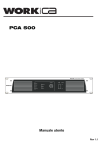
1
PA 9500 CDT
User Manual / Instrucciones de Usuario
BEFORE OPERATING THIS AMPLIFIER, PLEASE
CAREFULLY READING THIS OWNER'S MANUAL.
SAFETY PRECAUTIONS:
¡The following symbols are used on this instrument.
The lightning flash with arrowhead symbol, within an equilateral
triangle, is intended to alert the user to the presence of uninsurable
"dangerous voltage" within the product's enclosure that may be of
sufficient magnitude to constitute a risk of electric shock to persons.
! The exclamation point within an equilateral triangle is intended
to alert the user to the presence of important operating and
maintenance (servicing) instructions in the literature accompanying
the appliance.To avoid injury, death of personnel or damage to the
instrument, the operation must refer to an explanation in the user's
Manual or service Manual.
Protective grounding terminal.
~ Alternating current.
CONVENTIONS USED IN THIS MANUAL.
¡The following symbol marks indicating that for safety, the
operator should refer to the appropriate user's Manual.
CAUTION: This symbol marks indicating that for safety, the
operator's attention.
WARNING: Describes precautions that should be observed
to prevent the danger of injury or death to the user.
! Describes precautions that should be observed to prevent
damage to the instrument.
TABLE OF CONTENTS
1. Contents and features..................................................1
2. Caution.......................................................................2
3. Front Panel controls.....................................................3
4. Rear Panel controls......................................................4
5. Install and connections.................................................5
6. Operation....................................................................8
7. Trouble shooting........................................................11
8. Specifications............................................................12
9. Example of possible connections.................................14
1. FEATURES AND GENERAL DESCRIPTION
The CDT series have 90W output RMS, CD series
with a compact disc player; CDT series with both of a compact disc
player and digital tuner features.
a. High quality design and construction.
b. Full frequency response: 50Hz to 15,000 Hz at ¡3dB.
c. Low distortion and noise level.
d. 4 balance microphone inputs,2 auxiliary inputs.(Placed on the
rear panel)
e. Mic1 is unbalance inputs, has an automatic mute feature, during
broadcasting, it may insert other sound signal and make the
playing sound signal of CD, turning, AUX muting.
f. With compact disc player with power and volume control(CDT
series).
g. With Digital tuner (only CDT series).
h. Isolated transformer outputs complete with 4,8,16 ohms, 70v, 100v.
j. Individual bass and treble tone controls.
k. Master volume control.
l. Send output for a tape recorder.
m. Self-protection circuitry design.
n. Built-in LED bar graph output level meter.
2. CAUTION
CAUTION
¡Before replacing the AC fuse, be sure to unplug the power cord
from the AC outlet, otherwise may cause a chock hazard.
¡Do not block any of the ventilation openings.
¡You shall hold the plug firmly to avoid pull the power line and risk
Occurrencing when you pull the power line out from AC outlet.
¡ If the equipment gives out any strange odor or smoke, please turnoff it immediately and disconnect the power from the supply cable.
¡1¡
!
HANDLE THE POWER CORD GENTLY.
¡To disconnect the plug from the AC outlet, pull on the plug itself,
not on the cord.
¡Disconnect the plug from the AC outlet whenever the unit is to be
left unused for an extended period of time.
¡ Do not placer furniture or the heavy objects on the cord, and avoid
dropping heavy objects on it. Also do not make a knot in the cord.
¡Check if the power supply is being shot down, the power line is
pulled out from outlet and other lines connecting this unit are also
disconnected.
!
PLACE THE UNIT ON A FIRM AND LEVEL SURFACE.
Avoid installing it:
¡ In moist or humid places.
¡ Close to heating equipment or in places exposed to direct sunlight.
¡ In a direct draft from an air conditioner or in other very cold locations.
¡ In placers subject to excessive vibration or dust.
¡ In poorly ventilated places.
!
MOVING THE UNIT.
¡ Befo re moving the unit, be sure to unplug the power cord from the
AC outlet and disconnect all wires antennas and other components.
CAUTION: DO NOT OPEN THE CABINET.
¡ Do not attempt to service this unit. Tampering with internal
components can cause fire or shock, and may void tour guarantee.
If water or a small object enters the unit, unplug the power cord
Immediately and call a qualified technician or consult our company,
or consult an authorized.
WARMING: CAUTION FOR TEMPERATURE
¡ Don't touch the screw around the ventilation holes in the bottom
board. When heat-sink working, the screw and the board temperature rises higher.
! Before you press the power button to on. Be sure to the all volume
VR to minimum.
¡2¡
!
CLEANING.
¡ Remove dust by wiping the unit with a soft, dry cloth. If necessary, use
a soft cloth lightly dampened with mild soapy water; then a dry cloth.
Never use benzene, thinner alcohol or other volatile agents, and avoid
spraying insecticides near the unit, other fluids with very strong volatility and flammability for cleaning the in it body.
!
INTERFERENCE.
¡ If connecting interference takes place in source circuit, the THD
will be more that 10%.
3. FRONT PANEL CONTROLS
6
4
5
OUTPUT
1
3
5
7
2
4
6
ME
UP
BAND
TUN VOL.
+3dB
0
MULTIPLEX PROFESSIONAL AMPLIFIER
FM
105.95
-5
MHZ
DOWN POWER
-7
-20
3
PW
MASTER
AUX-1
STOP
B.SKIP/REW
F.SKIP/FF
PLAY/PAUSE
PROG
REPEAT
BASS
TREBLE
2
LEVEL
PLAY
-10
01
+10
-10
+10
OPEN/CLOSE
AUX-2
0
MIC-1
MIC-1
MIC-2
MIC-3
MIC-4
POWER
10
COMPACT DISC PLAYER
10
11
12 9
8
7
1
1.POWER ON-OFF SWITCH: Applies line power. Two-position
button switch for on-off modes.
2. MASTER VOLUME CONTROL: Adjusts overall gain of unit.
3. OUTPUT LEVEL METER: Indicates output level.
4. TUNER VOLUME CONTROL: Adjusts gain of TUN-VOL respectively.
5.TUNER MODULAR: Digital TUNER Modular.
6.BASS TREBLE CONTROL: Adjusts Bass TREBLE respectively.
Tone is flat at center.
7.MIC 1-4 VOLUME CONTROL: Adjusts gain of MIC 1-4 respectively.
¡3¡
8.MIC-1 PHONE JACK: Connects to a microphone of unbalanced
low impedance (30-600 ohms).
9.AUX-1,AUX-2 VOLUME CONTROL: Adjusts gain of AUX-1,
AUX-2 VOL.
10. COMPACT DISC PLAYER: DIGITAL display.
11. CD volume control: Adjust gain of CD vol.
12. CD power switch: Applies CD power. Two position buttons
switch for on-off modes.
4. REAR PANEL CONTROLS
1
2
7
4
8
9
ANTENNA
75£
OUT PUT
DC SW.
COM
RATED SUPPLY VOLTAGE:
230V~50Hz
CAUTION
ON
RISK OF ELECTRIC SHOCK.
DO NOT OPEN.
OFF
4£
8£ 16£
70V 100V
!
CAUTION : TO REDUCE THE RISK OF FIRE OR ELECTRIC
SHOCK, DO NOT REMOVE THE COVER (OR BACK ) OR EXPOSE
THIS PRODUCT TO RAIN OR MOISTURE. FOR CONTINUED
PROTECTION AGAINST RISK OF FIRE-REPLACE ONLY WITH
THE SAME TAPE AS MARKED. NO USER SERVICEABLE PARTS
INSIDE. REFER SERVICING TO QUALIFIED SERVICE PERSONNEL.
SEE INSTRUCTION MANUAL.
Use only with a 250V fuse
CLASS ¢ WIRE
CLASS ¢ WIRE
RE-APPLY THE TERMINAL COVER AND FASTEN THE SCREWS
T3A 250V
MIC-4
MIC-3
MIC-2
MIC-1
RECV
AUX-2
GND
AUX-1
WARNING
L
+
24V
NO-OUTDOOR USE.
DO NOT BLOCK ANY OF THE VENTILATION OPENINGS.
R
SEND
3
5
6
1. AC INPUT: AC main connects to AC power source (AC FUSE).
2. AC SELECTOR: AC selector switch (100V-120V/220V-240V).
3. DC INPUT: DC power supply DC 24V battery.
4. DC SWITCH: Two-position button switch for on-off modes.
5. MIC-1~MIC-4 INPUT: Connects to microphone balance type.
6. RCA JACK: Connects phonograph&cassette. Radio output.
7. ANTENNA: Connects FM antenna.(only CDT series).
8. ANTENNA: AM loop antenna.(only CDT series).
9.OUTPUT LOW&HIGH IMPEDANCE: Connects to speakers
(Low impedance & High impedance).
Caution:
The AC selector changed only by manufacturer.
¡4¡
5. INSTALL AND CONNECTIONS
Caution:
¡ Before using this unit for the first time, be sure that the
appliance's voltage is in accordance to your mains supply. Connecting this unit only to grounded mains outlet.
¡ Re-apply the output terminal cover and fasten the screws after
connected.
¡ Do not block any of the ventilation openings.
¡ Surface with a minimum distance of 1 M from the back or side
plate to the wall.
1. DC power or battery supply's connections.
¡ The unit will also operate from an external 24v battery or other
direct current source with negative (-) as ground. Power connections are made at the DC terminal strip on the rear panel.
¡ If AC power supply fails, transfer to DC power is instantaneous,
automatic and silent, if the DC switch push to on condition on rear
panel.
¡ The battery power supply is not operated by the primary switch.
If switch to battery power is desired, press the DC switch push to
on/off condition on rear panel.
¡ The amplifier is not capable of recharging the connected battery.
Thus, it is recommended to have a suitable device at hand.
When the amplifier is operated on the DC power source, the nominal power handling capacity drops by approximately 20%.
¡ DC power supply or battery supply's figure.
+
24V
-
-
+
2. Input connections
Battery
MICROPHONE CONNECTIONS:
AS witchcraft type A3M Microphone connector or equivalent is
required for making connections to the Microphone inputs and audio
shielded cable is required for all balanced and unbalanced microphone input connecting.
12Vdc
¡5¡
BALANCED MICROPHONE INPUT CONNECTIONS:
Using shielded cable, connect the two center conductors of the
cable to prongs #2 and #3 of the A3M Microphone connector.
Connect the shield of the cable to prong#1of the A3M Microphone
connector.
UNBALANCED MICROPHONE INPUT CONNECTIONS:
Using shielded cable, connect the center conductor of the cable
to prong #2 of the A3M Microphone connector. Connect the shield
of the cable to prong #1 of A3M Microphone connector.3
MICROPHONE
RECEPTACLE
ON REAR PANEL
MICROPHONE
CONNECTIONS FOR HI-Z
OR LO-Z UNBALANCED
MICROPHONE OPERATION
PUSH
SHILED
CENTER
CONDUCTOR
MICROPHONE
RECEPTACLE
ON REAR PANEL
MICROPHONE
PUSH
CONNECTIONS FOR LO-Z
BALANCED MICROPHONE
OPERATION
SHILED
CENTER
CONDUCTORS
MICROPHONE WRIING CONNECTIONS
MIC
Unbalanced microphone
Single pole phone pug
¡6¡
PRIORITY PAGING:
The amplifier features a transistorized circuit which automatically removes all program material for the amplifier and
permits microphone #1 to take over for special or emergency
announcements.
This electronic switch is operated from the microphone, which
must contain a single-pole switch, normally open for actuating
this circuit.
A turntable with a high impedance ceramic or crystal cartridge
may be connected to an AUX. input.
The external " ACOUSTIC EQUALIZER " is connected to the
SEND and RECV receptacles on the rear panel of the amplifier,
SEND is connected to the input of the external "equalizer" and
RECV to the output of the external.
3. Output connections.
Caution.
¡ To avoid the risk of electrical shock, never touch the bare
conductors leading to the output terminals of the amplifier
when it is in operation. Show the possible connections of the
"output" speaker terminal accessible by removing the protective
cover. Bear in mind the following rules:(see following).
¡ Re-apply the output terminal cover and fasten the screws after
¡ Constant the low impedance lines.
(1) The total impedance of the speakers connected must
correspond to that selected on the amplifier's output terminals.
(2) The sum of the power capacities of the speakers must be
no lower than the amplifier's power capacity.
(3) The length of the connecting cables must be short as possible; with equal of line that CLASS ¢ wire .
¡Constant the high voltage lines.
(1) Each speaker must be equipped with a line transformer
that with an input voltage, with equal of the line that CLASS
¢wire .
¡7¡
(2) The sum of the power capacities of the speakers must not
exceed the output power capacity of the amplifier.
(3) The length of the connecting cables must be short as possible; in any case, the cables of long-distance must be covered
in cross-section.
6.Operation
BASIC OPERATION
(1) Press the POWER button to ON, then the power lights up;
press again to turn the power off, then the power lights extinct.
(2) Bass control, modifies the low-frequency sound of the left
and right channels as much as +/- 10dB. Set this control at a
suitable position for your taste and room acoustics.
(3) Treble control, modify the high-frequency sound of the left
and right channels as much as +/- 10dB. Set this control at a suitable position for your taste and room acoustics.
(4) CD,AUX-1,AUX-2, MIC, all have independent volume control,
unbalance input mic1 has priority in them. When the signal input
the mic1, the playing signal of AUX. CD. radio should be muting,
the mic1 signal will priority playing. turn the VOLUME clockwise
to increase the volume and counter clock wise to decrease it.
(5) Master volume control, turn the VOLUME clockwise to increase the volume and counter clockwise to decrease it, the volume
of the front, center, and rear channels is changed at the same
time.
(6) LISTENING TO BROADCASTS. You can use auto, manual
or preset tuning to select a radio station. Before use this function,
must press the radio's power button. When you press it again,
this function was cut off.
(7) AUTO TUNING. If broadcast signals are strong and there is
no interference, auto Tuning is possible.
a. Press the "BAND" button to select Am or Fm band.
¡8¡
b. Press the "UP" or "DOWN" button for a little time about 5 second,
tuning will start automatically and stop at a broadcast station
frequency with sufficient signal strength.
(8) MANUAL TUNING. Auto tuning may be impossible if the
broadcast signal is weak. If so, use manual tuning.
a. Press the "BAND" button to select the desired band.
b. Press the "UP" or "DOWN" button for a little time about 2 second,
until the desired station frequency is reached: Each time the button
is pressed, the frequency changes by a step; When the button is
kept pressed, the frequency changes continuously in sequence.
(9) PRESET TUNING. The receiver has a memory for up to 7
preset stations. If the station frequencies are stored in this memory,
they can be tuned by select the numbers on the front panel.
(10) MANUAL PRESETTING. Up to 7 stations can be preset at
random, regardless of the reception band.
a. Turn in the station to be memorized using the auto or manual
tuning.
b. Press the "ME" button first or second, then the memory indicator
lights up for 5 seconds.
c. Select the number on the front panel and press it while the
memory indicator is flash.
d.Repeat steps a to c to preset other stations.
(11)RECALLING THE PRESET STATIONS. Select the preset
number of the desired preset station with the number buttons on
the front panel, then press the "up" or "down" to changed it.
(12)NOTES about tuning.
a. If the end of the frequency range is reached during the auto
or manual tuning, Tuning will continue from the opposite end.
b. When memorizing a new station, the previously memorized
station on the same channel number is cleared. In the event of
a power failure or wen the receiver is disconnected from the AC
outlet, the memorized stations are maintained for approximately
2 weeks.
¡9¡
(13) Play the CD tape.
When you press the CD power switch's button to on, then the
compact disc player will display, at the same time, tell you that
the CD player at the state of ready work.
a. Press the open/close button, the CD window will push out,
then take a CD tape in it. Next, press the same button again
and after wait about for 5seconds press the play/Pause button,
at this time, the CD player was working at the normal conditions.
b. CD function buttons.
" "CD power switch with two-position for ON-OFF modes, before
press it, please turn off the master volume.
"OPEN/CLOSE", Press the open/close button, the CD window will
push out; press the same button again the CD window will push in.
"PLAY/PAUSE", when press it, the CD player will playback;
press the same button again, the CD player will pause play.
LEVEL. The VR is CD volume control with adjust gain of CD
volume "STOP", when press it, the CD player will stop playback;
"B.SKIP/REW", when press it, the CD player will backward skip;
"F.SKIP/FF", when press it, the CD player will forward skip;
"REPEAT", when press it, the CD player will repeat to play the
same song ,press it again the CD player will repeat to play all.
If press it again, the CD player will return to normal conditions
of playing.
"PROG" when press it, the CD player can setup in accordance
with your favoured selections.
NOTE: Before you press the power button to on. Be sure to the
all volume VR to minimum.
7.Trouble shooting
This unit is designed for trouble-free operation. Most problems
users encounter are due to operating errors. So, if you have a
problem, first check this list for a possible solution. If the problem
persists, do not attempt to service this unit by yourself, consult
your authorized service centers or a highly qualified personnel.
¡10¡
IF THE PROBLEM IS ---
MAKE SURE THAT THE ---
No lights illuminate when
POWER button is pressed.
Unit is plugged into a live outlet,
was the AC fuse opened
The fan no work.
unit is plugged into a live outlet,
was the AC fuse opened
Correct input function selector
button has been pressed
Volume is turned up
Speakers are connected properly
No sound is heard.
Unit output is intermittent or
Check the AC power or DC power
continuously buzzing or screech supply is proper
No output from one or more
channels.
No display of compact disc
player
No output of compact disc
player
Tuner sound has a large
amount of interference, or
tuner sound distorts and/or
volume level is too low
Tuner is intermittent or
continuously buzzing or
screech
Stations cannot be preset
¡11¡
Cables are not defective:
Check/replace speaker cables
or line.
The signal source is operating and
providing proper signal output to
this unit
Check the" "CD power switch,
is normal.
Check the CD tape clearing or
damage, Clear the laser-head
The antenna is properly connected
The antenna is properly located
The antenna is set in the proper
direction
The antenna is adequate to receive
the desired station.
The unit is away from fluorescent
lights, motors, Tvs and other
electrical appliances
After pressing the ME button, the
ME button, is pressed while the
display "P1/P2" indicator blinks.
8. Specifications
Type
Model
Power output
Output regulation
Outputs
Mixer power amplifier
90W series
with CD/CDT
Rated: 90W
max: 120W
Less than 2dB no load to full load
Speaker output (balanced)
90W 4£ (18.9V), 8£ (26.8V), 16£ (37.9V),
70V(54.4£),100V(111£)
120W 4£ (21.9V), 8£ (30.9V), 16£ (43.8V),
70V (42£),100V (83£)
RECV: 4.7K Ohms, 650mV
SEND: 600ohms, 1V
Frequency Response
50~15,000Hz
Total harmonic distortion
Less than 3% at 1KHz, rated power
Signal to noise radio
(Tone control centered)
All volume controls C.C.W.: 80dB below
rated power
Microphone
:80dB below
rated power
AUX 1, AUX 2
:80dB below
rated power
Tone controls
BASS
TREBLE
Input
INPUT 1: (MIC 1) 600 ohms, -60dB (BAL.UNBAL)
INPUT 2: (MIC 2) 600 ohms, -60dB (BAL)
INPUT 3: (MIC 3) 600 ohms, -60dB (BAL)
INPUT 4: (MIC 4) 600 ohms, -60dB (BAL)
(AUX 1) 10k ohms, -15dB
(AUX 2) 20k ohms, -20dB
¡12¡
: ¡10dB at 100Hz
: ¡10dB at 10KHz
Controls
INPUT 1 volume control
Tone controls (BASS, TREBLE)
INPUT 2 volume control
CD volume control
AUX-1 volume control
INPUT 3 volume control
MASTER volume control
INPUT 4 volume control
TUNER volume control
AUX-2 volume control
Indicator
Power indicator (LED)
LED output level meter
AC power supply
DC power supply
AC power consumption
see rear panel's marked*
24V
256 WATTS
at rated output
DC power consumption
7.3A
at rated output
Dimensions
450mm(W)¡150mm(H)¡330mm(D)
Weight
11.5kg
Color
Black
* Caution:
The AC selector changed only by manufacturer.
¡13¡
9. Example of possible connections
0
0
70V
0
70V
0
100V
0
100V
0
100V
70V
ANTENNA
75£
OUT PUT
DC SW.
COM
RATED SUPPLY VOLTAGE:
230V~50Hz
CAUTION
ON
4£
8£
16£
70V
100V
!
RISK OF ELECTRIC SHOCK.
DO NOT OPEN.
OFF
CAUTION : TO REDUCE THE RISK OF FIRE OR ELECTRIC
SHOCK, DO NOT REMOVE THE COVER (OR BACK ) OR EXPOSE
THIS PRODUCT TO RAIN OR MOISTURE. FOR CONTINUED
PROTECTION AGAINST RISK OF FIRE-REPLACE ONLY WITH
THE SAME TAPE AS MARKED. NO USER SERVICEABLE PARTS
INSIDE. REFER SERVICING TO QUALIFIED SERVICE PERSONNEL.
SEE INSTRUCTION MANUAL.
Use only with a 250V fuse
CLASS ¢ WIRE
CLASS ¢ WIRE
RE-APPLY THE TERMINAL COVER AND FASTEN THE SCREWS
T3A 250V
MIC-3
MIC-4
MIC-2
MIC-1
RECV
AUX-2
GND
AUX-1
WARNING
NO-OUTDOOR USE.
DO NOT BLOCK ANY OF THE VENTILATION OPENINGS.
L
-
+
24V
R
SEND
-
+
12Vdc
Battery
Speaker Speaker
Speaker
4£
8£
16£
CD player
AM/FM tuner
Cassette recorder
OUTPUT
1
3
5
7
2
4
6
ME
UP
BAND
TUN VOL.
+3dB
0
MULTIPLEX PROFESSIONAL AMPLIFIER
FM
105.95
-5
MHZ
DOWN POWER
-7
-20
PW
MASTER
AUX-1
STOP
B.SKIP/REW
BASS
TREBLE
F.SKIP/FF
LEVEL
PLAY
PLAY/PAUSE
PROG
REPEAT
-10
01
+10
-10
+10
OPEN/CLOSE
0
10
AUX-2
COMPACT DISC PLAYER
¡14¡
MIC-1
MIC-1
MIC-2
MIC-3
MIC-4
POWER
¡Use this unit with pre-ampfilier.
ANTENNA
75£
OUT PUT
DC SW.
COM
RATED SUPPLY VOLTAGE:
230V~50Hz
CAUTION
ON
RISK OF ELECTRIC SHOCK.
DO NOT OPEN.
OFF
4£
8£
16£
70V 100V
!
CAUTION : TO REDUCE THE RISK OF FIRE OR ELECTRIC
SHOCK, DO NOT REMOVE THE COVER (OR BACK ) OR EXPOSE
THIS PRODUCT TO RAIN OR MOISTURE. FOR CONTINUED
PROTECTION AGAINST RISK OF FIRE-REPLACE ONLY WITH
THE SAME TAPE AS MARKED. NO USER SERVICEABLE PARTS
INSIDE. REFER SERVICING TO QUALIFIED SERVICE PERSONNEL.
SEE INSTRUCTION MANUAL.
Use only with a 250V fuse
CLASS ¢ WIRE
CLASS ¢ WIRE
RE-APPLY THE TERMINAL COVER AND FASTEN THE SCREWS
T3A 250V
MIC-3
MIC-4
MIC-2
MIC-1
RECV
AUX-2
GND
AUX-1
WARNING
NO-OUTDOOR USE.
DO NOT BLOCK ANY OF THE VENTILATION OPENINGS.
L
+
24V
R
SEND
OUT
IN
EQUALIZER
DC24V
OUTPUT
FM ANT
LINE OUT
L
R
DC FUSE
OFF
4W COM 70V 100V
Monitor TEL.
VOL. VOL.
Z1
Z2
PRE
OUT
Z3
CAUTION:
ELECTRIC SHOCK HAZARD
DO NOT REMOVE COVER.
REFER SERVICING TO
QUALIFIED PERSONNEL.
SEE INSTRUCTION MANUAL.
Connect other AMPLI FI ER'S rear-amplifier.
1234
1: for CD
2: for Tuner
3: for Tape
4: for AUX IN
COM COM COM COM
F
E
FUSE
COM
E
-
US
FUS
DC POWER
ON
+
LINE MIC
PHANTOM
24V
LINE MIC
PHANTOM
24V
LINE MIC
PHANTOM
24V
LINE MIC
PHANTOM
24V
INPUT 1
INPUT 2
INPUT 3
INPUT 4
R
Use only with a 250V fuse
L
LINE
230V~50Hz
GND
+
-
1W 8£
T
Prority
i
MAIN
IN
R
G
Tel. Paging
BALANCED
¡Use this unit with rear-ampfilier.
ANTENNA
75£
OUT PUT
DC SW.
COM
RATED SUPPLY VOLTAGE:
230V~50Hz
CAUTION
ON
RISK OF ELECTRIC SHOCK.
DO NOT OPEN.
OFF
4£
8£
16£
70V 100V
!
CAUTION : TO REDUCE THE RISK OF FIRE OR ELECTRIC
SHOCK, DO NOT REMOVE THE COVER (OR BACK ) OR EXPOSE
THIS PRODUCT TO RAIN OR MOISTURE. FOR CONTINUED
PROTECTION AGAINST RISK OF FIRE-REPLACE ONLY WITH
THE SAME TAPE AS MARKED. NO USER SERVICEABLE PARTS
INSIDE. REFER SERVICING TO QUALIFIED SERVICE PERSONNEL.
SEE INSTRUCTION MANUAL.
Use only with a 250V fuse
CLASS ¢ WIRE
CLASS ¢ WIRE
RE-APPLY THE TERMINAL COVER AND FASTEN THE SCREWS
T3A 250V
MIC-4
MIC-3
MIC-2
MIC-1
RECV
AUX-2
GND
AUX-1
WARNING
NO-OUTDOOR USE.
DO NOT BLOCK ANY OF THE VENTILATION OPENINGS.
L
+
24V
R
SEND
OUT
IN
OUT
EQUALIZER
CD player
AM/FM tuner
Cassette recorder
¡15¡
Equipson, S.A.
www.equipson.es
[email protected]