1
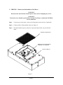
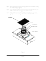
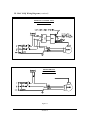
*** READ AND SAVE THESE INSTRUCTIONS *** MAC 10 IQ FAN FILTER MODULE INSTALLATION AND SERVICE MANUAL STANDARD and RSR MODELS Mac 10 is a registered Trademarks of the Envirco Corporation, Albuquerque, New Mexico, U.S.A. US Patents 4,560,395 and 5,470,363 Other patents issued and pending in foreign countries Updated 4/6/01 READ AND SAVE THESE INSTRUCTIONS WARNING! TO REDUCE THE RISK OF FIRE, ELECTRICAL SHOCK, OR INJURY TO PERSONS, OBSERVE THE FOLLOWING : A. Installation work and electrical wiring must be done by qualified person(s) in accordance with all applicable codes and standards, including fire-rated construction. B. When cutting or drilling into wall or ceiling, do not damage electrical wiring and other hidden utilities. C. If this unit is to be installed over a tub or shower, it must be marked as appropriate for the application. D. Use this unit only in the manner intended by the manufacturer. If you have any questions, contact the manufacturer : ENVIRCO CORPORATION 5601 Balloon Fiesta Parkway N.E. Albuquerque, New Mexico 87113, U.S.A. Tel : (800) 545-6598 Fax : (505) 345-8875 Email: [email protected] ENVIRCO CORPORATION Eastern Regional Office 18238 Showalter Road Hagerstown, Maryland 21742, U.S.A. Tel : (800) 645-1610 Fax : (301) 714-4784 Email: [email protected] TRION-ENVIRCO European Operations Reith Way, West Portway Industrial Estate Andover, Hampshire, SP10 3TY, England Tel : +44 (0) 1264 364622 Fax : +44 (0) 1264 350983 Email: [email protected] E. Before servicing or cleaning unit, switch power off at service panel and lock service panel to prevent power from being switched on accidentally. MAC 10 IQ SERVICE MANUAL PAGE 1 Table of Contents Title Page I. INSTALLATION 3 II. SERVICE : CLEANING THE MAC 10 IQ PREFILTER 4 III. SERVICE : REMOVAL AND REPLACEMENT OF THE HEPA/ULPA FILTER 5 IV. SERVICE : REMOVAL AND REPLACEMENT OF THE ROOM SIDE REPLACEABLE FILTER (RSR) 6 V. SERVICE : REMOVAL AND INSTALLATION OF THE MOTOR 7 VI. ON/OFF SWITCH-SPEED/AIRFLOW ADJUSTMENTS 9 VII. TROUBLE SHOOTING 12 VIII. MAC 10 IQ WIRING DIAGRAMS 13 IX. MAC 10 IQ REPLACEMENT PARTS LIST 15 X. WARRANTY 16 XI. TESTING 16 MAC 10 IQ SERVICE MANUAL PAGE 2 I. INSTALLATION Note: The MAC 10 IQ Filter Unit is completely assembled at the factory with the exception of the optional ¼”(0.64 cm)-20 eyebolts, which can be used when hanging the unit from an overhead structure. Step 1. Carefully remove the unit from the shipping carton and inspect for any damage that may have occurred during transportation.(see Figure 1) Step 2. Wipe down plastic bag and move unit into clean room. Step 3. If using rigidly supported grid (usually 2” or wider), raise unit through ceiling and lower onto the gasketed grid. If using a flexible grid (typically supported with wires) the unit must be secured to an overhead structure with eyebolts, s-hooks and chain. A roll of high-density gasket has been provided for use with ungasketed grids. Step 4. Have an electrician wire the unit to the appropriate voltage (115V, 220V, 277V AC), according to the wiring diagram in section IX and local electric codes. If optional power cord was purchased, plug unit into a grounded receptacle. Figure 1 MAC 10 IQ SERVICE MANUAL PAGE 3 II. SERVICE : Cleaning the MAC 10 IQ Prefilter WARNING! Disconnect the unit from the electrical power source before attempting any service. Note: To keep the filter in top operating condition, washing the foam prefilter is recommended every three to six months. Step 1. To gain access to the prefilter, remove the ceiling panel next to the unit, if applicable. Step 2. Lift the prefilter off the prefilter frame.(see Figure 2) Step 3. Clean the prefilter by hand washing in water with a mild detergent or by using a vacuum cleaner. Allow prefilter to dry completely before replacing. Step 4. Install the prefilter back on the bracket, with the expanded metal screen facing down. PREFILTER SCREW (4) Figure 2 MAC 10 IQ SERVICE MANUAL PAGE 4 III. SERVICE: Removal and Replacement of the HEPA/ULPA Filter (Standard Unit) WARNING! Disconnect the unit from the electrical power source before attempting any service. Step 1. Remove unit from ceiling. Step 2. Remove the 10 screws holding the HEPA/ULPA filter to the lid assembly. Step 3. Lift the lid assembly off the HEPA/ULPA filter (see Figure 3). Discard the used filter as per requirements of the applicable regulations. Note: Before replacing with a new HEPA/ULPA filter, carefully inspect the new filter for any visible damage. Also inspect the gasket in the “tee” bar to insure a tight seal. Replace as necessary. Step 5. Replace with the new HEPA/ULPA filter and assemble by reversing the above steps. REMOVE 10 SCREWS Figure 3 MAC 10 IQ SERVICE MANUAL PAGE 5 IV. SERVICE : Removal and Installation of the Room Side Replaceable Filter WARNING! Disconnect the unit from the electrical power source before attempting any service. Step 1. Remove the diffuser screen by shifting it to one side and lowering it out of the housing. Step 2. While supporting the filter, remove the six screws and clips and lower the filter.(see Figure 4) Note : Before replacing with a new filter, carefully inspect the new filter for any visible damage. Step 3. Replace with the new HEPA/ULPA filter and assemble by reversing the above steps. Note: Tighten filter clip bolts as necessary to insure no bypass leakage. DO NOT over tighten. FAN FILTER UNIT RSR FILTER HEPA OR ULPA DIFFUSER SCREEN FILTER CLIP AND BOLT Figure 4 MAC 10 IQ SERVICE MANUAL PAGE 6 V. SERVICE: Removal and Installation of the Motor WARNING! Disconnect the unit from the electrical power source before attempting any service. WARNING! Electrical service should be performed by licensed electricians or authorized ENVIRCO service technicians. Step 1. To gain access to the motor, remove the ceiling panel next to the unit, if applicable. Step 2. Lift the prefilter off the prefilter frame.(see Figure 5) Step 3. Disconnect both the power connector (5 pin) and control cable (16-pin) from the motor. REMOVE PREFILTER REMOVE MOTOR/BLOWER ASSEMBLY (6 SCREWS) ON/OFF SWITCH Figure 5 MAC 10 IQ SERVICE MANUAL PAGE 7 Step 4. Remove the six screws to free the venturi ring and remove the motor/blower assembly from the lid assembly.(see Figure 6) Step 5. Using a 5/32”(0.40 cm) Allen wrench remove the blower wheel from the motor shaft. Remove motor from the venturi ring by remove the three # 10 bolts. Step 6. Replace with the new motor and reassemble by reversing the above steps. Set the spacing between the venturi ring and the blower wheel at 0.06”(0.15 cm) clearance. PREFILTER MOTOR VENTURI RING BLOWER WHEEL ON/OFF SWITCH Figure 6 MAC 10 IQ SERVICE MANUAL PAGE 8 VII. ON/OFF Switch - Speed/Airflow Adjustment All MAC 10 IQ units are equipped with a two-position rocker switch (ON/OFF), which is located on the side of the electrical box, on top of the unit. All units are furnished with the digital speed control to enable adjustment of airflow at any setting within the recommended performance range. The digital control speed is mounted on the electric control box and can be adjusted without opening the box (see figure 7). Airflow/speed is adjusted by rotating either ten percent per increment adjustment for an approximately 10 fpm change in airflow and the one percent increment for fine tuning changes in airflow (see Figure 8). The table below gives the expected airflow at each adjustment percentage on the 2x4 standard unit, supplied with an Envirco filter. For other sizes please contact the factory. Units are factory preset at 99% (maximum airflow) 1% adjustment switch (1%, 2%, 3%, etc) fine adjustment 10% adjustment switch (10%, 20%, 30% etc) large adjustments Figure 7 Setting Airflow (fpm) (Sealevel) Airflow (fpm)(5000 ASL) 10% 20% 30% 40% 50% 60% 70% 80% 90% 100% 42 51 64 74 80 89 95 105 113 123 63 73 83 94 107 114 130 135 143 158 Figure 8 MAC 10 IQ SERVICE MANUAL PAGE 9 Infrared Remote Control (Optional) The Flow-Set is a handheld infrared remote control configured to adjust the Envirco Mac 10 IQ unit. An EVO/ECM-IRC control sends the IQ motors a FLOW INDEX and a GO signal. The motor sends back a status signal that is connected to a red lamp. The control includes an infrared remote receiver. The Flow-Set handheld remote sends infrared remote commands to the EVO/ECM-IRC control, allowing remote adjustment of the IQ motor. Using the Flow-Set, you can turn the motor on/off, adjust the flow index from 1-100 and read the current settings. Point the Flow-Set at the Flow-Set target (red lamp if the motor is on) on the equipment. Operate the on/off button or any of the four ↑/↓ buttons. The green lamp near the Flow-Set target lights, indicating you are in an adjustment session. Continue to operate the on/off button or any of the four ↑/↓ buttons to achieve the desired settings. Press the Enter button to save your new settings and exit the adjustment session. Press the Clear button to delete your new settings, revert to the original settings and exit the adjustment session. If you enter an adjustment session and do not make any adjustments for 15 minutes, the adjustment session automatically clears. Use the Clear button to read the current settings. Point the Flow-Set at the Flow-Set target and press the Clear button. A green lamp begins to flash indicating the signal was received. The flash sequence indicates the current flow index. The sequence occurs in two sets. The tens (1st) set uses long flashes to indicate the tens digit. The units (2nd) set uses short flashes to indicate the units digit. An extra long flash in the tens set or the units set indicates the value of the corresponding digit is zero. − A flow index of 24 flashes two longs, then 4 shorts. − A flow index of 89 flashes 8 longs, then 9 shorts. − A flow index of 30 flashes 3 longs, then an extra long. − A flow index of 04 flashes an extra long, then 4 short. − A flow index of 100 flashes 10 longs, then an extra long. Use the On/Off button to turn the motor on or off. Point the Flow-Set at the Flow-Set target on the equipment and press the on/off button. If you press Enter while the motor is off, the motor stays off, even through a power on/off cycle. Adjust the flow index using the ↑/↓ buttons. The ↑/↓ button pair on the left adjusts the index ↑/↓ 10. The ↑/↓button pair on the right adjusts the flow index ↑/↓1. Using the ↑/↓10 pair, you can quickly move the index up and down. Using the ↑/↓1 pair, you can precisely set the index to achieve the desired flow. During an adjustment session, the green lamp blinks each time you MAC 10 IQ SERVICE MANUAL PAGE 10 make a valid entry. If the flow index is already 100, and you try to increase the flow index, the green lamp does not blink, and the increase does not occur. If the flow index is at 91 and you press the ↑10 button, the green lamp does not blink and the increase does not occur because your entry would take the index above 100. When the flow index is greater than 90, use the ↑1 button to increase the index. The ↓1 and ↓10 keys respond in a like manner when you try to set the flow index below 1. (Zero is not a valid flow index). Batteries Two AA batteries power the EVO/IRC-Masterfs. Remove the sliding door on the back of the unit to expose the battery compartment. Remove the old batteries. Insert the new batteries in the position indicated by the battery pictures molded into the bottom of the battery compartment. The battery spring clips are difficult, so you may need to use a small screwdriver to "shoehorn" the batteries into place. For maximum battery life, store the EVO/IRC-Masterfs so the buttons are not pressed. While current drain is minimum when the unit is not sending infrared signals, some battery current is drawn to sense the pressed key. MAC 10 IQ SERVICE MANUAL PAGE 11 VIII. Trouble Shooting: Low Air Velocity Step 1. Check prefilter media; replace or clean as necessary. Step 2. Adjust digital speed control for higher blower output. Step 3. Check power supply for proper voltage, amperage and distribution frequency. Step 4. Replace HEPA filter if the air velocity remains low. High Air Velocity Step 1. Adjust digital speed control for lower blower output. Non-Laminar Flow and/or Excessive Contamination Step 1. Insure that no large obstructions are upstream of airflow pattern. Step 2. Determine that no other air-moving devices are operating in or around clean room which disrupt room’s airflow pattern. Step 3. Check air velocity and if low, conduct the “Low Air Velocity” procedure outlined above. Step 4. Conduct smoke and photometer test on HEPA filter. Seal or replace HEPA filter as necessary. MAC 10 IQ SERVICE MANUAL PAGE 12 IX. MAC 10 IQ Wiring Diagrams DIGITAL SPEED CONTROL WIRING DIAGRAM Figure 9 DIGITAL SPEED CONTROLWITH OPTIONAL INDICATOR LIGHT (LED) WIRING DIAGRAM Figure 10 MAC 10 IQ SERVICE MANUAL PAGE 13 IX. MAC 10 IQ Wiring Diagrams (continued) OPTIONAL CONTROL UNIT WIRING DIAGRAM RECEIVER UNIT WIRING DIAGRAM Figure 11 MAC 10 IQ SERVICE MANUAL PAGE 14 X. MAC 10 IQ Replacement Parts List: Description Quantity ENVIRCO Part Number per unit 120V 240V 277V _______________________________________60 Hz_______50 - 60 Hz______60 Hz_ Prefilter Motor Two-Position Switch Digital Speed Control Modbuss Control HEPA filter (STANDARD): 2’ x 2’ 2’ x 3’ 2’ x 3.5’ 2’ x 4’ HEPA filter (RSR): Available upon request 1 1 1 1 1 62981 63589 63739 63672 63631 62981 63589 63739 63672 63631 62981 63655 63739 63672 63631 1 1 1 1 69514-004 69514-019 69514-020 69514-006 69514-004 69514-019 69514-020 69514-006 69514-004 69514-019 69514-020 69514-006 Optional Accessories: Indicator Light (LED) Power cord Remote Infrared Speed Control Control System 12”(30.48 cm) diameter A/C intake collar Gel seal filter (RSR unit only) ULPA filter (Standard and RSR) Replacement parts are available through your authorized ENVIRCO representative. If you cannot locate a representative in your area, contact our Parts Department at: ENVIRCO CORPORATION 5601 Balloon Fiesta Parkway NE Albuquerque, NM 87113, U.S.A. Tel: (505) 798-4403 Fax: (505) 345-8875 MAC 10 IQ SERVICE MANUAL PAGE 15 XI. LIMITED WARRANTY ENVIRCO CORPORATION (“ENVIRCO”) warrants the equipment will be free of defects in materials and workmanship under normal use for a period of three(3) years. The HEPA filter shall only be warranted against loading for a period of two(2) years when operated in clean room conditions. ENVIRCO’s sole obligation under this warranty is to repair or replace any parts of the equipment which are defective for a period of three(3) years from the invoice date, provided that the repair or replacement is actually performed within the three(3) year period from the invoice date. The buyer agrees to assume any incidental expenses including but not limited to the cost of transporting the defective equipment to ENVIRCO’s repair facility. The buyer’s sole remedy under this limited warranty is the repair or replacement of any defective part of the equipment. ENVIRCO DISCLAIMS ANY IMPLIED WARRANTIES INCLUDING WARRANTIES OF MERCHANTABILITY AND FITNESS FOR A PARTICULAR PURPOSE. In no event shall ENVIRCO be liable for punitive, incidental, or consequential damages arising out of this sale, including, but not limited to damage to persons or property, loss of use, loss of time, inconvenience, equipment rental, loss of earnings or profit or any other commercial loss. This warranty excludes certain expendable items such as light tubes, prefilters, etc. ENVIRCO expressly disclaims and excludes from this warranty any responsibility for equipment failures and/or defects attributable to improper maintenance, abuse, accident or modification of the equipment (such as application of an adjustable frequency drive). XII. TESTING Each MAC 10 IQ filter unit is thoroughly tested at the factory before shipment. However, because of the “rigors” of shipping, ENVIRCO encourages its re-test after installation. ENVIRCO recommends that the customer contact an independent organization, with technicians trained and experienced in performance evaluation and maintenance of clean air equipment. Some of the testing procedures performed on the MAC 10 IQ include PS challenge of HEPA filters to assure specified performance, along with air velocity measurement and adjustment tests. Recommended Testing All units that are airflow tested at Envirco are tested using a Shortridge Airdata Multimeter 870 with a Velgrid head. The recommended method of reading is to place one corner of the Velgrid head 1-1/4” from the corner of the filter face and then take four reading evenly spaced along the four foot side, then repeat these reads for the other long side. This gives a total of eight reading to test the unit. All advertised data is based on using the Velgrid with 8 readings (128 velocity points). Envirco recognized the using 8 reading during a cleanroom start-up may be time consuming and recommends using 3 Velgrid readings taken on a diagonal, as shown below. MAC 10 IQ SERVICE MANUAL PAGE 16 Recommended Testing – 8 readings with a Velgrid Factory Approved Testing – 3 readings with a Velgrid MAC 10 IQ SERVICE MANUAL PAGE 17