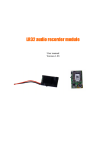
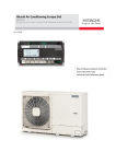
1
PHYSITEMP INSTRUMENTS INC
154 Huron Avenue
Clifton, NJ 07013 U.S.A.
Tel: 973-779-5577
Fax: 973-779-5954
e-mail: [email protected]
OPERATING MANUAL
BAT-10
Multipurpose Thermometer
12.0
REPAIRS AND RECALIBRATION
12.1 In the event that a BAT-10 Thermometer is to be returned for repair and recalibration please
pack it with care and send it prepaid to:
Physitemp Instruments, Inc.
Service Department
154 Huron Avenue
Clifton, NJ 07013 USA
Please include with the instrument:
(1) A note describing any problems encountered.
(2) The name and telephone number of the user or other person we can contact.
(3) The complete return address for shipping.
12.2 A Service Manual for the BAT-10 is available at additional charge. It includes schematic,
component locator, trouble-shooting guide and complete calibration instructions. Specified test
equipment is required for recalibration or other servicing. Consult Physitemp for further service
information by telephone at:
973-779-5577 or fax 793-779-5954
12.3 Physitemp Instruments, Inc. warrants this instrument to be free from defects in material and
workmanship for 12 months from date of shipment. Repair or replacement will be made at no
charge at the discretion of Physitemp if the defect is not the result of misuse or abuse. Physitemp
accepts no consequential liabilty for delay in delivery, alleged faulty performance of the product, or
for any other cause.
Cables and probes are considered expendable and are not covered by this warranty. See separate
warranty enclosed with probe.
For your protection, please pack returned items carefully, and insure them against possible damage
or loss in transit. Physitemp will not be responsible for damage resulting from careless or inadequate packaging. Please return freight prepaid.
During the warranty period, the instrument may also be returned for a free calibration check.
11
11.11 Measurements in Electronics. BAT-10 and ICT-4 provide the quickest and cheapest
method of getting accurate reading on both discreet components and integrated circuits used in
electronic equipment. ICT-4 has two important differences from the regular MT-4 probe. There is
a 5 1/2” handle suitable for use in the hand or in a micromanipulator and the micro-thermocouple
protrudes slightly beyond the steel sheath and has some thermal isolation from it. This probe was
designed for use on areas of 5-100 microns in diameter and is used perpendicular to the surface to
be measured. The heat loss described in 11.3 occurs and temperature readings are slightly low -normally about 0.5°C low. Each probe can be readily calibrated on a larger surface. First lay it
parallel to the surface and note the reading. Then take a reading with it perpendicular to the surface; note the difference. Add this difference to the subsequent reading when using the perpendicular position.
11.12 BAT-10 with a suitable probe has the ability to measure surface gradients, giving almost
instant readings at each point. This feature enables heat sinks to be designed without guesswork,
for maximum efficiency with minimum metal. It is equally easy to check the adequacy of thermal
bonding between a power transistor or rectifier and its heat sink. General purpose probe BT-1 is
suitable for this and many other measurements. When probes such as BT-1 and the larger HT-1
and HT-2 are used for surface measurements, speed of response and accuracy can often be
improved by use of a heat conductive material such as ‘thermal grease’ or silicone grease applied
between the probe and surface. Note: BT-1, HT-1 and HT-2 should not be used on electrically conductive surfaces where voltages are present as the sensor is connected to the stainless steel sheath.
The following probes are isolated and suitable for use on electrical equipment: RET-1, ESO-1, IT14, IT-18, IT-21, TFT series.
10
rial. In liquids and semi-solids, the tip and sheath are simply immersed; on solid surfaces, the sheath
is laid against the surface.
Here is a useful rough rule: Heat leakage effects are substantially reduced when an amount
of probe equal to 10 or more sheath diameters is immersed or laid on the surface. For
example, with a probe of 1/16” diameter:
10 x 1/16” = 10/16” = .625” = the minimum immersion depth
11.7 Errors between thermocouple probes. All Physitemp clinical probes and sensors are made with
thermocouple wire that has been specially tested to meet our own stringent standards. Our clinical
probes are guaranteed accurate to within 0.1oC in the range 0-50oC. Copper-Constantan (type T)
thermocouples from other manufacturers are not normally this accurate. Probes made from wire to
“special limits of error” may be accurate to ±0.5°C in this range. This interchangeability of sensor,
including microprobes, is a major advantage of Physitemp thermocouple thermometer
11.8
Measurements in Liquids. These are quite easy to make, because there is good thermal
contact between liquid and probe. The latter quickly reaches liquid temperature and readings can be taken within a few seconds. However, a
liquid which has been heated above or cooled below ambient will be
losing or gaining heat, and convection currents will give rise to temperature variations of up to several degrees. These variations can be reduced
by vigorous stirring. This simple precaution must always be taken.
11.9 Measurements of Air Temperature. Temperature can vary widely in different parts of a
room; differences of at least several degrees will usually be noted. When a microprobe is used to
indicate air temperature, readings will often fluctuate rapidly, responding to actual temperature
changes caused by air currents. Breathing near the microprobe will produce wide fluctuations.
These effects indicate the sensitivity of the BAT-10/microprobe combination, due to high discrimination of the instrument and almost instant response of the probe. Fluctuations can easily be eliminated by bringing the probe into contact with a metallic object, thus increasing its effective mass
and slowing the response. Using a larger probe will have the same results.
11.10 Measurements on Solid Surfaces. These are most easily made with surface probes such as
our BT-1 and MT-D. The right-angled tip provides the 10 diameters
of probe contact specified in Section 11.6. Straight probes may also
be used, provided that sufficient shaft length is in contact with the
surface to be measured. In general, the smaller the probe, the more
accurately it will measure the surface temperature of a solid. For
instance, an MT-29 microprobe, because of its small size, needs to
be in contact with the surface for as little as 1/8”. SST-1 has a 1/4” gold disc sensor. Gold is an
excellent conductor, and is non-allergenic and non-polluting. It makes a fine skin surface probe.
9
11.0
TEMPERATURE MEASUREMENT WITH THERMOCOUPLE SENSORS
11.1 The thermocouple is a simple and widely accepted device for measuring temperature. It
comprises two wires of dissimilar metals fused together to form a junction which produces an electrical output proportional to temperature. The National Institute of Standards and Technology
(NIST Monograph 125, 1974) has tabulated the voltage/temperature relationships of many commonly used thermocouple pairs; their tables on copper/constantan form the basis for calibration of
Physitemp thermometers.
11.2 At one time, accurate thermocouple temperature measurements needed elaborate potentiometers and reference to a source of known temperature, such as an ice bath. The advent of modern solid state devices has made possible the design of an inexpensive thermocouple thermometer
which is direct reading. The first of these was Bailey thermometer BAT-4, which was designed in
1969 and is now in use throughout the world. Your BAT-10 is an advanced version of the original
equipment using the latest low power digital technology and compensated electronic reference circuitry.
11.3 As compared with thermistor sensors which were formerly used exclusively in portable
thermometers, thermocouples have these advantages:
(a) Wide temperature range, e.g. -200°C to over +1300°C.
(b) High stability of output.
(c) Interchangeability - no recalibration required.
(d) Accuracy traceable to NIST calibrations.
(e) Low cost; users can even make their own sensors.
(f) Microscopic size when needed, as in Physitemp microprobes.
(g) Nearly instant response.
(h) Better measurement accuracy due to low mass with smaller heat loss.
11.4 The main disadvantage of the thermocouple, low sensitivity, was overcome by the development of auto zeroing amplifiers which are now used in all Physitemp thermometers. This type of
amplifier is essentially drift-free. It makes possible an electronic thermometer which is permanently
calibrated, just like a mercury thermometer. The following notes may help the user to avoid some
of the errors most frequently made in temperature measurement.
11.5 Faulty measurement technique with any type of thermometer can produce errors of several
degrees. Errors attributed to "out of calibration" equipment can often be corrected by a simple
change of technique.
11.6 Thermocouple probes, like all other temperature sensing devices, must be placed so that
they reach, as closely as possible, the temperature of the material to be measured. Probes are tipsensitive, but when measuring the temperatures of liquids, semi-solids or hard surfaces, it is not
sufficient to bring only the tip into contact with the material being measured. This is because there
will be loss of heat along both the thermocouple wires and their sheath, so readings will be low.
The effect can be greatly reduced if part of the metal sheath is also placed in contact with the mate-
8
10.0
SPECIFICATIONS
Temperature Range
and Resolution:
-200°C to +400°C, 1°C resolution
-100°C to +199.9°C, 0.1°C resolution
Differential
Temperature Range:
-19.99°C to +19.99°C. Linearization centered at 40°C
See Section 5.0
Accuracy:
1°C, (±1 digit)
0.1°C, (±1 digit)
0.01°C (±1 digit)
1° Range
0.1° Range
Diff. Range
Repeatability:
One least significant digit
Calibration:
Conforms to National Institute of Standards and Technology
(Monograph 125)
Sensors:
Any Physitemp type T Thermocouple
Ambient Operating Range:
15 - 45°C
Readout:
3 1/2 digits
Batteries:
BAT-10 - 4 alkaline “C” cells (Battery life, 1000 hours)
BAT-10R - (rechargeable unit) - 4 NI-Cads
Special Display
Indications:
LO-BAT appears on display when battery voltage is low, but
several hours of life remain.
INPUT appears on display when open probe or input
fault condition has occured.
ALARM, acitivated by user supplied external 5V logic level
Analog output:
Non-linearized set at 1.5V corresponding to temperature of 401°C
Linearized (when supplied) 1mV/count
7
7.0
ANALOG OUTPUT FOR CHART RECORDING
7.1
NON-LINEARIZED ANALOG OUTPUT. BAT-10 is supplied with an analog output that is
proportional to the input thermocouple voltage with respect to analog common. This is adequate for
most stirp chart recording applications where small temperature ranges are involved. The output
bears a non-linear relationship to temperature and thermocouple tables can be used to compensate
for linearity changes over wider temperature ranges. The non-linear output can be found on pin 1 of
the 9-pin connector on the back of the instrument. The return is pin 7. The 9-pin male D-shell connector (part # 6-2072) should be ordered if this output is to be used. It can also be obtained from
any electronic parts store.
7.2
LINEARIZED ANAOLOG OUTPUT. This is only supplied if specified at time of order. It
can be retrofitted only at factroy. The 9-pin male D-shell connector is included with this option.
The output is directly proportioanl to the number of counts displayed and is equal to 1mV/count
with respect to digital common. The linear analog output can be found on pin 6 of the 9-pi D-shell
connector on the rear of the instrument. IMPORTANT: The return is digital common, pin 8.
for example: display reads 19.86
number of counts = 1986
output is 1.986V
Please note: The linearized analog output uses a D/A converter which updates at the same rate as
the display (approximately 3 times per second) and therefore when temperature is changing rapidly,
step changes may be seen in the output voltage as the converter updates.
8.0
8.1
BATTERY REPLACEMENT
NON-RECHARGEABLE INSTRUMENTS
IMPORTANT: Use only alkaline batteries
Switch instrument OFF. Turning counter-clockwise, unscrew the two plastic caps from the battery
holders on the back panel. Slide old batteries out and replace with fresh “C”cells.
Install with positive terminals towards the plastic screw caps. Replace caps.
8.2
RECHARGEABLE INSTRUMENTS
Follow the instruction above but install four rechargeable N-Cad batteries.
9.0
RECHARGING THE BATTIERIES
9.1
Plug the Physitemp AC charger (9V @ 50 to 200mA AC) into AC input socket on the back
panel and connect to AC supply. Allow 16 hours for complete recharging.
With Ni-Cad batteries installed, the unit may be continuously operated from the AC recharger.
WARNING
The AC input socket is present on all versions (rechargeable and non-rechargeable.)
NEVER attempt to recharge or power a BAT-10 with non-rechargeable batteries.
The batteries may explode or leak. This is a fire hazard and can result in internal damage to the instrument.
BAT-10 can be field upgraded to BAT-10R with our RCK-10 recharger kit, which includes Ni-Cad batteries
and wall-mount charger.
6
When using BAT-10 for differential measurements not centered on the 40°C reference, a correction must be introduced to accomodate changes in sensitivity and linearization at different reference temperatures.
In general, differential measurements are quite correct when the difference reading is small and
both sensors are in the 20-60°C range. A correction is required when: (a) differences greater than
1°C are to be measured (b) both sensors are not within 20-60°C (c) when measurements are not
centered on the 40°C reference. Calculation of true temperature can be made with reference to
Appendix 1.
Note: Input - the digital display warning for open or faulty probe is inactive in the differential
mode (DIFF)
Consult factory for further technical information and details in specific applications.
6.0
6.1
AUXILIARY OUTPUT CONNECTOR (optional)
The 9-pin D-shell connector on the back panel is used for the
following auxiliary connections:
All signals are with respect to digital ground unless otherwise specified
• Non-linearized analog output, with respect to analog ground (see Section 7.1)
• Linearized analog output, optional (see Section 7.2)
• Data True: A gating signal, active low. The number of oscillator pulses during this
period is four times the count displayed
For example: Display reads 38.1°C = 381 counts
Number of oscillator pulses in the data true period is 381x4=1524
• Oscillator output: 53KHz (±20%)
• Alarm input: User supplied signal, active low. 5V logic level
• Sign out: Low when negative
• Analog common
• Digital common
• V+: Positive supply
Consult factory for further information: (Phone 973-779-5577)
Connection diagram:
5
1
9
6
PIN #
1
2
3
4
5
6
7
8
9
5
FUNCTION
Non-linear Analog output
Data True
Oscillator Output
Alarm In
Sign Out
Linear Analog Output
Analog Common
Digital Common
V+
4.2
Select the required range by depressing the 1° or 0.1° RANGE SELECT pushbutton.
Be sure that the DIFF pushbutton is not depressed.
4.3
Direct measurements are made with inputs 1 and 2. If two probes are being used, just
depress the PROBE SELECT pushbutton which corresponds with the sensor to be monitored.
5.0
5.1
5.2
5.3
DIFFERENTIAL MEASUREMENT TECHNIQUES
Specifications of the differential range are as follows:
Resolution
0.01°C
Accuracy
0.01°C (±1 digit)
Repeatability
0.01°C
Linearity is centered at 40°C
Range
-19.99 to +19.99°
USING THE DIFFERENTIAL RANGE:
Before making measurements, check and adjust the DIFF ZERO as follows:
Remove probes from all sockets.
Select DIFF range pushbutton.
Select DIFF ZERO.
Wait for about 30 seconds for reading to stabilize.
Adjust ZERO with screwdriver until it displays 0.00
Release DIFF ZERO
Connect probes to INPUTS 2 and 3 only.
Read temperature difference between probes:
If probe in input 2 is at the higher temperature, the temperature
reading will be positive.
If probe in input 2 is at the lower temperature, the temperature
reading will be negative.
When making differential measurements with 0.01° resolution:
• Keep instrument away from drafts or sources of heat.
• When instrument is moved from one location to another, allow at least one hour
for temperature stabilization before use.
• Allow 10-15 minutes after plugging in probes before taking readings.
• While making measurements, never touch probe plugs or allow them to come
into contact with sources of heat or cold.
• Check DIFF ZERO periodically to ensure it has not drifted. Reset as necessary
using ZERO control.
• When making differential measurements in an electrically conductive medium, at
least one of the probes should be electrically isolated from the medium. The following Physitemp probes are isolated: RET-1, ESO-1, IT-14, IT-18, IT-21, IT-23,
IT-1E, TFT series. We can also supply an insulated version of our MT-23 microprobes if requested.
4
1.0
INTRODUCTION
1.0
Physitemp laboratory thermometers are compact, digital thermometers for use with type T
thermocouple sensors. The BAT-10 thermometer has two probe inputs for direct temperature readings with a resolution of 0.1°C or 1°C. A third input is used when differential measurements are
made. On the differential range, temperature resolution is 0.01°C.
BAT-10 accepts all Physitemp type T thermocouple probes.
2.0
INITIAL INSTALLATION
2.1
Set the handle/angle bracket to the position most convenient for your application. Pull out
both side bars slightly at the same time. Adjust as necessary then allow to snap back into place.
2.2
BATTERY OPERATED UNITS are supplied with four alkaline “C” cells installed and are
ready for operation.
2.3
RECHARGEABLE UNITS are supplied with fully charged Nicad batteries installed and a
charger kit that is also an AC adaptor.
To recharge and for AC use, connect the power jack on the recharger kit to the AC INPUT socket
on the back of the instrument. Plug the charger into a live outlet. Charger is for use with 110115V AC unless otherwise specified on your order. Charger will be labelled for correct voltage.
See Section 9.0 for further information.
3.0
OPERATING INSTRUCTIONS
3.1
The following instructions are printed on a label on the top panel of the BAT-10. They are
reprinted here in case the label is ever defaced. See Sections 4.0 and 5.0 for detailed information.
TEMPERATURE RANGE
-200°C
3. SPECIAL DISPLAY INDICATIONS
RESOLUTION
to +400°C
l
1°C
-100°C
to +199.9°C
0.1°C
Differential -19.99°C
to +19.99°C
0.01°C
- Probe is above or below limits of range.
LO BAT - Replace or recharge the batteries
INPUT
- Probe, input connector or lead may be faulty.
Replace probe at input selected.
4. BATTERY REPLACEMENT (non-rechargeable units)
1. TO MEASURE TEMPERATURE
Insert plug of any type T thermocouple probe into input 1 or 2.
Switch ON. Select range. Select probe input 1 or 2. Ensure DIFF
ZERO button is not depressed. Read temperature.
USE ONLY ALKALINE BATTERIES
Switch instrument OFF. Unscrew two plastic caps from holders on
back by turning counter-clockwise. Discard old batteries and
replace with fresh “C” cells. Install all four batteries with positive
terminals toward plastic screw caps. Replace caps
2. TO MEASURE DIFFERENTIAL TEMPERATURE
5. RECHARGING (rechargeable units only)
Connect probes to input 2 AND 3. Select DIFF range to measure
differential temperature between these probes. Select DIFF ZERO
ADJUST. Use screwdriver to set zero until display reads 0.00.
Release DIFF ZERO to read differential temperature of probe 2
with respect to probe 3. See manual for more detail instructions.
Plug AC charger (9V @ 250 mA) into AC INPUT socket on back
of instrumement. Allow 16 hours for complete recharging.
With Ni-Cad batteries installed the unit may be continuously
operated from AC recharger.
Note: Input 3 is only activated in differential mode. It is not
possible to measure absolute temperature with this input.
Model BAT-10
Serial Number:
4.0
TEMPERATURE MEASUREMENT
4.1
Any type T thermocouple (Copper-Constantan) can be used with the BAT-10.
Thermocouple sensors made with “special limits” wire are accurate to 0.5°C in the range 0-50°C.
If better accuracy is required, Physitemp’s microprobes and clinical probes should be used.. These
are manufactured with specially graded wire and are guaranteed accurate to 0.1°C in the range 050°C. See Section 11.0 for more information on temperature measurement with thermocouples.
3
BAT-10 FRONT PANEL
TEMPERATURE
RANGE SELECT
POWER ON
PROBE
SELECT
PROBE
INPUTS
BAT-10 REAR PANEL
AUXILIARY
OUTPUT
CONNECTOR
(See page 5)
BATTERY
COMPARTMENTS
AC INPUT SOCKET
FOR BAT-10R
(RECHARGEABLE
VERSION)
2
OPERATING MANUAL
BAT-10
Multipurpose Thermometer
Section
1.0
INTRODUCTION
2.0
INITIAL INSTALLATION
3.0
OPERATING INSTRUCTIONS
4.0
TEMPERATURE MEASUREMENT
5.0
DIFFERENTIAL MEASUREMENT
TECHNIQUES
6.0
AUXILIARY OUTPUT CONNECTOR
7.0
ANALOG OUTPUT FOR CHART RECORDING
8.0
BATTERY REPLACEMENT - ALKALINE CELLS
9.0
RECHARGING THE BATTERIES
10.0
SPECIFICATIONS
11.0
TEMPERATURE MEASUREMENT
WITH THERMOCOUPLES
12.0
WARRANTY AND SERVICE
Appendix 1
QX U:\CW shared\Operating Manuals\ EB BAT-10
Instructions for the use of the BAT-10 Differential Range
with base temperature other than 40.00°C
Rev 2
1