1
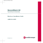
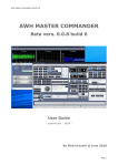
Optipay® BV Series
Installation Guide
May, 2008
May, 2008
Installation Guide
Optipay® BV Series
DBV-300 / DBV-301 / DBV-302 Bill Validators
This document contains information for installing and configuring the Optipay®
DBV-30X Series Bill Validators. All three units are designed to work in systems
where quick, quiet and reliable bill acceptance and validation is required. In
addition to easy changeability and multi-sized Cash Boxes, the DBV-300,
DBV-301 and DBV-302 contain the following features:
• $1, $5, $10, $20, $50 and $100 bill
(banknote) acceptance capable
• 4-Way bill/banknote acceptance with high
security
• Coupon acceptance capable (Magnetic &
Barcode)
• Utilizes magnetic and multi-wave length
sensors for accurate validation
• Color LED indicators for simple fault
diagnostics
• Flash memory programming via Palm
Pilot® PDA or PC base station
• Available in both Stack-Up (SU) and StackDown (SD) model configurations
• Includes a Bottle Mask or Snack Mask
Front Bezel.
PRIMARY OPTIPAY™ BV BILL VALIDATOR SERIES COMPONENTS
Figure 1 illustrates the primary components of a Bottle Mask Fitted DBV-30X.
JCM is a registered trademark of JCM American Corporation. All other product names
mentioned herein may be registered trademarks or trademarks of their respective companies.
Furthermore, ™, ® and © are not always mentioned in each case throughout this publication.
1. 18-Pin Molex connector (on left
side).
2. Large/Red DIP Switch Block (on
left side).
3. Small/White DIP Switch Block (on
left side).
4. Bill inserting/dispensing slot.
5. PCB Edge Connector (Presently
unused).
6. LED indicators.
7. 8-pin RJ-45 Interface port for Palm
Pilot® handheld use (on right side)
* Required cable shown below.
8. RC-10 recycler communication
Port (on right side).
9. Cash Box (at rear).
9
8
1
7
6
5
2
3
4
925 Pilot Road, Las Vegas, Nevada 89119
Office & Technical Support: (800) 683-7248 (option 5 after hours), FAX: (702) 651-0214
E-mail: [email protected]
http://www.jcm-american.com
Part No. 960-100180RA_ Rev. A
20
© 2008, JCM American, Corporation
Bottle Masked DBV-30X Front Right View
* 6” RJ-45 Extension Cable
Figure 1 Primary Bottle Mask Fitted DBV-30X Component Parts
Part No. 960-100180RA_ Rev. A
1
© 2008, JCM American, Corporation
Optipay® BV Series
Installation Guide
Installation Guide
Figure 2 illustrates the primary components of a Snack Mask Fitted DBV-30X.
May, 2008
OPERATIONAL CHECK
Once the unit is installed, perform the following steps to ensure the DBV-300,
301 or 302 is communicating with the Host Machine’s Bus.
1. 18-Pin Molex connector (on left
side)
2. Large/Red DIP Switch Block (on
left side)
3. Small/White DIP Switch Block (on
left side)
4. Bill inserting/dispensing slot
5. PCB Edge Connector (Presently
unused)
6. LED indicators
7. 8-pin RJ-45 Interface port for Palm
Pilot® handheld use (on right side) *
Required cable shown below.
8. RC-10 recycler communication Port
(on right side)
9. Cash Box (at rear)
9
8
1
7
1. Power up the unit.
2. Wait for the LEDs on the front panel to stop flashing. When the LEDs are solid
the unit is in its operational mode.
3. Insert a bill, and verify that the Host Machine displays an approprate value for th
bill inserted and/or performs the desired vend function.
If further detailed instruction is necessary, refer to the primary DBV-30X
Service Manual (Part No. 960-000103R).
6
5
2
3
4
* 6” RJ-45 Extension Cable
Snack Masked DBV-30X Front Right View
Figure 2 Primary Snack Mask Fitted DBV-30X Component Parts
INSTALLATION PROCESS
During the installation process, access to the four (4) mounting holes will be
easier if the Cash Box and Lower Sensor Assembly are removed prior to
installation. To remove these assemblies proceed as follows:
CASH BOX
1. Slide the white release tab located on
top of the Validator forward
(See Figure 3) and
2. Pull the Cash Box up and out to
remove it.
Release
Tab
Slide
to
Front
Cash
Box
Figure 3 Cash Box Removal
SENSOR MODULE
1. To remove the Lower Sensor Assembly, press up [1] on the release rod
locking bar and
2. Pull the module outward [2] from the
frame (See Figure 4).
Release Rod
1 Push Rod Up
2 Pull Out
Figure 4 Sensor Module Removal
Part No. 960-100180RA_ Rev. A
2
19
© 2008, JCM American, Corporation
Optipay® BV Series
Installation Guide
BILL ACCEPTANCE TESTS
Installation Guide
May, 2008
MOUNTING INSTRUCTIONS
The Bill Acceptance Test provides a quick and easy way to check the basic
operation of the DBV-30X Bill Validator. While in the Bill Acceptance Mode,
the DBV will accept, validate, and stack bills in the Cash Box. The LEDs on the
front bezel of the unit will flash to indicate the denomination of bills inserted.
To run the Bill Acceptance Test, place the DBV into the Test Mode as follows:
1.
2.
3.
4.
Remove any power that is currently applied to the DBV.
On DIP Switch Block #1, set SW-8 to the “ON” position.
Reapply all power to the DBV.
Verify that the Diagnostic LEDs (Red - Yellow - Green) are all steady lit, and that
the Bezel LEDs are also lit. The DBV is now in 'Test Mode'.
5. On DIP Switch Block #1, set SW-1, SW-2, SW-3, and SW-4 to “ON”.
6. On DIP Switch Block #1, set SW-8 to “OFF”. (this enables the test).
The DBV is now ready to accept bills.
7. Insert a variety of bills as desired.
The Front Bezel LEDs will flash to indicate the bill denomination inserted as
follows:
• 1 Flash = $1.00
• 2 Flashes = $5.00
• 3 Flashes = $10.00
• 4 Flashes = $20.00
8. When done testing, perform the following steps to return the DBV to normal
operating mode:
9. On DIP Switch Block #1, set SW-8 to “ON”. (this disables the test).
10. On DIP Switch Block #1, set SW-1, SW-2, SW-3, and SW-4 to “OFF”.
11. On DIP Switch Block #1, set SW-8 to “OFF”.
12. Recycle power to the unit.
Caution: Turn the equipment power OFF before
removing or replacing any components.
The DBV-30X Series Validators work best when flush mounted in a vertical
position. A properly mounted Bottle Masked Validator is illustrated in Figure 5a.
A properly mounted Snack Masked Validator is illustrated in Figure 5b. This
configuration initially offsets the unit 3/4” back from the mounting surface using
spacer as illustrated in Figure 5b.
Install the Bill Validator using the four (4) mounting access holes provided and
tighten the four (4) mounting nuts in the order illustrated in Figure 5c.
a
b
Flush mount
90° to Gasket
Flush
Mount
to
Gasket
Flush
Mount
90°
90°
Gasket
(if required)
c
Flush mount
90° to Door
Insert
Gasket
on Studs
First
4
3
2
Additional
3/4”-Inch
Spacer
90°
Flush mount
to door
1
90°
Flush mount
to Door
NOTE: If a custom mounting kit is required, contact
the individual Vendors JCM installation guide.
Figure 5 Bottle & Snack Mask Mounting Considerations
Caution: Tighten mounting nuts until snug. DO NOT
over tighten.
Part No. 960-100180RA_ Rev. A
18
3
© 2008, JCM American, Corporation
Optipay® BV Series
Installation Guide
Installation Guide
May, 2008
DBV-300 POWER SUPPLY CONNECTIONS
DIAGNOSTICS
The DBV-300 requires a customer supplied +12V DC Power supply. Power
consumption is 0.3 Amps in Stand-by Mode and 0.6 Amps in normal operation.
However, the maximum current draw is nominally 1.5 Amps.
JCM recommends using a power source capable of supplying +12V DC (±5%)
at 2.5 Amps.
If the Bill Validator came with a pre-wired interface harness, connect the 12 Volt
Power Source to Wire 3 (power) and Wire 4 (power return) of the 18-Pin
Harness Connector, and then connect it to the 18-Pin Interface Receptacle
located on the left side of the Bill Validator.
If a pre-wired harness is not being used, connect the 12 Volt Power Source
directly to pins 3 and 4 of the 18-Pin Interface Receptacle located on the left side
of the Bill Validator.
Figure 6 illustrates the DBV-300 Power Input Port Pin Configuration.
The DBV-30X series of Bill Validators contain intelligent tri-colored (3 way)
Diagnostic LED Panel (See Figure 16).
Vdd @ Pin #3 = +12Volt DC Power
Vss @ Pin #4 = +12Volt DC Ground
Figure 6 DBV-300 Power Input Port Pin Configurations
DBV-301 POWER SUPPLY CONNECTIONS
The DBV-301 requires a customer supplied +24V DC Power supply. Power
consumption is 0.2 Amps in Stand-by Mode and 0.4 Amps in normal operation.
However, the maximum current draw is nominally 0.9 Amps.
JCM recommends using a power source capable of supplying +24V DC (±5%)
at 2.5 Amps.
If the Bill Validator came with a pre-wired interface harness, connect the 24 Volt
Power Source to Wire 1 (power) and Wire 2 (power return) of the 18-Pin
Harness Connector, and then connect it to the 18-Pin Interface Receptacle
located on the left side of the Bill Validator.
If a pre-wired harness is not being used, connect the 24 Volt Power Source
directly to pins 1 and 2 of the 18-Pin Interface Receptacle located on the left side
of the Bill Validator.
Figure 7 illustrates the DBV-301 Power Input Port Pin Configuration.
Figure 16 DBV-30X Tri-colored LED Panel
The LED Panel is located on the Lower Sensor Assembly (See Figure 17), and
provide an aid when troubleshooting. During normal operation, the Green LED
will be lit. The LEDs will flash when an error condition exists. The number of
times an LEDs flashes depends on the type of error encountered. Figure 17 lists
the LED Error Code flash definitions. For more detailed help in troubleshooting
operational problems, refer to the DBV-30X Operating and Maintenance
Manual (Part No. 960-000103R).
The Figure 17 Table lists the DBV-300 & 302 LED Error Code flash definitions.
Yellow
LED
Green
LED
Red
LED
Sensor Module Error Code Flash Indications
Number of Flashes
Diagnostic Description
Red
Yellow
Green
OFF
OFF
SOLID
OFF
1
OFF
2
OFF
OFF
STACKER ERROR / CHECK CASH BOX
Vdd @ Pin #1 = +24Volt DC Power
OFF
3-4
OFF
NOTE JAMMED / CHECK NOTE PATH
Vss @ Pin #2 = +24Volt DC Ground
OFF
10
OFF
CASH BOX POSITION / CHECK CASH BOX
OFF
OFF
1-8
LAST NOTE REJECTED / IF PROBLEM PERSISTS EITHER CLEAN
NOTE PATH OR CONTACT JCM
OFF
OFF
9-10
LAST NOTE INHIBITED / REJECTED BY DBV OR HOST
OFF
OFF
11-15
LAST NOTE REJECTED / IF PROBLEM PERSISTS EITHER CLEAN
NOTE PATH OR CONTACT JCM
Figure 7 DBV-301 Power Input Port Pin Configurations
DBV / OK / READY
CASH BOX FULL / CHECK CASH BOX
Figure 17 DBV-30X Error Codes
Part No. 960-100180RA_ Rev. A
4
17
© 2008, JCM American, Corporation
Optipay® BV Series
Installation Guide
ID-0D3 Photo Coupled MDB Serial Interface
The Multi Drop Bus (MDB) Serial Interface is used for communication and
control in a wide variety of Vending Machine equipment and a wide variety of
MDB compatible devices. The JCM DBV-301 Bill Validator is well suited for
use in this application due to its ability to operate directly from the MDB Bus 24
Volt DC supply voltage. Once installed, the unit communicates with the
Vending Machine Controller (VMC) and/or other MDB compatible devices.
Input/Output connection terminals for Photo Coupled MDB Communications
are provided within the 18-Pin Interface Connector located on the left side of the
DBV Unit. Table 10 lists the associated signal names and connections terminals
for the ID-0D3 MDB Serial Format.
Table 10 Photo Coupled MDB Signal Names and Descriptions
Pin
No.
Signal
Name
1
VDD1
DBV-301 24 VDC Power Terminal (See Figure 7 on page 4)
2
VSS1
DBV-301 24 VDC RTN Power Terminal (See Figure 7 on page 4)
3
NC
4
NC
5
TXD2
OUT
6
RXD2
IN
7
SG2
Photo Coupler Signal Ground from Bill Acceptor (See Figure 13 on page 10)
8
NC
No Connection
I/O*
Installation Guide
May, 2008
DBV-302 POWER SUPPLY CONNECTIONS
The DBV-302 operates directly from a nominal 117V AC alternating current
Line Voltage of 50/60 Hertz, and comes pre-wired directly from JCM for this
voltage supply.
NOTE: The Power Harness extending from the left side of the DBV-302
terminates in a 9-Pin Molex Connector. In order to connect the required
117V AC to this harness, a JCM power cord adaptor (Part No. 400100137R) will be required. The required adaptor is illustrated in Figure 8.
AC Power
Cord Adaptor
Function & Signal Description
No Connection
No Connection
Photo Coupler Output Signal Line from Bill Acceptor (See Figure 13 on page 10)
Photo Coupler Input Signal Line from Bill Acceptor (See Figure 13 on page 10)
9
NC
No Connection
10
NC
No Connection
11
NC
No Connection
12
NC
No Connection
13
NC
No Connection
14
NC
No Connection
15
NC
No Connection
16
NC
No Connection
17
NC
No Connection
18
NC
No Connection
Figure 8 DBV-302 117 Volt AC Power Cord Adaptor
* I/O (In/Out) viewed from the Bill Validator side.
DIP Switch Block #2: During normal operation, all switches on DIP Switch
Block #2 should be set to “OFF” when using the ID-003 MDB Interface
Protocol. If the Firmware version being used is capable of supporting a
secondary protocol (as listed in the applicable Software Information Sheet), then
DIP Switch #2/Switch 8 may be set to “ON” to properly select it.
Part No. 960-100180RA_ Rev. A
16
5
© 2008, JCM American, Corporation
Optipay® BV Series
Installation Guide
Installation Guide
DIP SWITCH LABELS AND SETTINGS
The DBV-30X Bill Validator features two banks of DIP Switches. The switch
blocks can be found in a recessed area located on the left side of the DBV
directly below the 18-Pin Harness Interface Receptacle. A label affixed to the
side of each DBV indicates where the DIP Switches are located, and how each
switch is numbered. Figure 9 illustrates the label differences between the early
and later version DBV DIP Switch Blocks.
1
2
Early
Version
Label
May, 2008
Table 9 ID-044 DIP Switch Block #2 Pulse Output Format Settings
6
5
4
3
Pulse Width
Pulse Count
SW2-1
SW2-2
SW2-3
SW2-4
50 ms / 300 ms
--------
OFF
OFF
---
---
ON
50 ms / 50 ms
--------
ON
OFF
---
---
ON
--------
$1 = 1 Pulse
---
---
OFF
OFF
ON
--------
$1 = 2 Pulse
---
OFF
(No. of Pulses)
SW2-8
---
ON
--------
$1 = 3 Pulse
---
---
OFF
ON
ON
--------
$1 = 4 Pulse
---
---
ON
ON
ON
ON
Figure 15 provides the pin connection data for ID-044 Pulse Interface operation.
/Vend @ Pin #11 = Accepted Denomination
Signal
/Enable @ Pin #14 = Bill Inhibited (Hi) /
Accepted (Low) Signal
Later
Version
Label
/Busy @ Pin #16 = Acceptor Operating Signal
/ABN @ Pin #17 = Acceptor Error Signal
3
/Full @ Pin #18 = Cash Box Full Signal
1. JCM Logo
2. JCM Main Office Address
3. Upper DIP Switch Block
4. DIP Switch Locating Arrow
5. Interface Connector Pin Label
6. Lower DIP Switch Block
Figure 15 DBV-300 ID-044 Pulse Interface Data Pin Configurations
Figure 9 Early & Later Version DIP Switch Side Label
The switch settings will vary depending on the operating mode presently active,
the options selected, and the communication protocol being used.
The DIP Switch located immediately below the 18-Pin Harness Interface
Receptacle is DIP Switch #1. The DIP Switch located directly below DIP
Switch #1 is DIP Switch #2.
On early model DBV units, DIP Switch Block #1 is larger in size than DIP
Switch Block #2, and is White in color. On later model DBV units the two DIP
Switches are the same size and the switches of DIP Switch #1 are Red in color.
Each DIP Switch Block contains eight (8) individual two position, single pole
switches that can be set to either “ON” or “OFF”. The switches are numbered
from 1 to 8, left to right, upward from the bottom of the DBV Unit. A switch is
considered “OFF” when down (towards the DBV front Bezel), and “ON” when up
(towards the DBV Cash Box). See Figure 10 for the typical switch layouts.
Later Version DIP Switches
Early Version DIP Switches
Lower DIP Switch Block
(Switch #2)
Upper DIP Switch Block
(Switch #1)
Lower DIP Switch Block Upper DIP Switch Block
(Switch #2)
(Switch #1)
Figure 10 Typical DBV DIP Switch Layouts
Part No. 960-100180RA_ Rev. A
6
15
© 2008, JCM American, Corporation
Optipay® BV Series
Installation Guide
ID-044 Pulse Interface
Input/Output connection terminals for ID-044 Pulse Data Communications are
provided within the 18-Pin Interface Connector located on the left side of the
DBV Unit. Table 8 lists the associated signal names and connections terminals
for the ID-044 Pulse Format.
Table 8 ID-044 Pulse Signal Names and Descriptions
Pin
No.
Signal
Name
I/O*
Installation Guide
During normal operation, the user may opt to enable or disable the acceptance of
certain bill denominations. Not all Bill Validators accept every denomination
listed. The Operating Firmware installed in your DBV will determine which
currency denominations are supported. Denomination selection is accomplished
by setting DIP Switch #1 switches to either “ON” or “OFF” according to Table 1.
Table 1 DIP Switch Denomination Settings
Function & Signal Description
Switch No.
Position
DIP Switch Function
1
VDD1
DBV-301 24 VDC Power Terminal (See Figure 7 on page 4)
2
VSS1
DBV-301 24 VDC RTN Power Terminal (See Figure 7 on page 4)
3
VDD1
DBV-300 12 VDC Power Terminal (See Figure 6 on page 4)
4
VSS1
DBV-300 12 VDC RTN Power Terminal (See Figure 6 on page 4)
5
NC
No Connection
6
NC
No Connection
OFF
Enable Denomination 3 Acceptance
7
NC
No Connection
ON
Disable Denomination 3 Acceptance
OFF
Enable Denomination 4 Acceptance
ON
Disable Denomination 4 Acceptance
8
NC
No Connection
9
NC
No Connection
SW-1
SW-2
SW-3
SW-4
OFF
Enable Denomination 1 Acceptance
ON
Disable Denomination 1 Acceptance
OFF
Enable Denomination 2 Acceptance
ON
Disable Denomination 2 Acceptance
OFF
Enable Denomination 5 Acceptance
11
VEND
Accepted Denomination Signal (Active LO)
ON
Disable Denomination 5 Acceptance
12
NC
No Connection
OFF
Enable Denomination 6 Acceptance
13
NC
No Connection
ON
Disable Denomination 6 Acceptance
14
ENABLE
10
NC
15
NC
16
BUSY
No Connection
OUT
IN
SW-5
SW-6
OFF
Enable Denomination 7 Acceptance
No Connection
ON
Disable Denomination 7 Acceptance
Acceptor Operating Signal (Active LO)
OFF
Normal Mode
ON
Test Mode
Bill Inhibit (HI) / Accept (LO) Signal (Active LO)
17
ABN
Acceptor Error Signal (Active LO)
18
FULL
Cash Box Full Signal (Active LO)
* I/O (In/Out) viewed from the Bill Validator side.
DIP Switch Block #2 is used to select the desired ID-044 Pulse Width and
Pulse Count Output Format type. Table 9 on page 15 lists the related DIP
Switch settings for each Pulse format. Further details can be found on the
applicable Software Information Sheet available from the JCM Website at: http:/
/www.jcm-american.com/products/software.asp.
May, 2008
DIP SWITCH BLOCK #1 SETTINGS
SW-7
SW-8
The Operating Firmware currently installed in the DBV memory will determine
which bills are supported, and the switches to which they are assigned.
NOTE: Not all Firmware Loads support every bill denomination currently
in circulation! For Example:
A USA2 Firmware Load will support denomination acceptance from
$1 through $20, whereas
A USA3 Firmware Load will support denomination acceptance from
$1 through $100.
Refer to the applicable Software Information Sheet for DIP Switch
setting details relating to your particular currency denomination
acceptance.
Switch SW-8 on DIP Switch Block #1 determines whether the DBV operates in
'Normal Mode' or in 'Test Mode'. While in the 'Test Mode', a number of
performance and diagnostics tests are available. Refer to the Optipay® DBV30X Operation and Maintenance Manual (Part No. 960-000103R), or the
Optipay® System Quick Reference Guide (Part No. 960-000128R) for details
concerning individual performance and diagnostic tests when using this mode.
Part No. 960-100180RA_ Rev. A
14
7
© 2008, JCM American, Corporation
Optipay® BV Series
Installation Guide
DIP SWITCH BLOCK #2 SETTINGS
Installation Guide
May, 2008
Table 7 ID-002 DIP Switch Block #2 Pulse Output Format Settings
The switches on the DIP Switch #2 Block are used for selecting several
parameters, including whether the DBV is operating in Serial Mode or Pulse
Mode, the Pulse Width, and setting the number of Pulse Counts required.
Refer to information provided for each Communications Protocol detail outlined
on the following pages to determine the correct DIP Switch Block #2 settings for
your particular configuration. This information is also available in the
Software Information Sheet applicable to the systems specific Firmware Load.
Pulse Width
Pulse Count
50 ms / 300 ms
--------
(No. of Pulses)
SW2-1
SW2-2
SW2-3
SW2-4
OFF
OFF
---
---
SW2-8
ON
50 ms / 50 ms
--------
ON
OFF
---
---
ON
80 ms / 120 ms
--------
OFF
ON
---
---
ON
--------
ON
150 ms / 180 ms
ON
---
--------
$1 = 1 Pulse
---
---
OFF
OFF
ON
--------
$1 = 4 Pulse
---
---
ON
OFF
---
ON
ON
--------
$1 = 10 Pulse
---
---
OFF
ON
ON
--------
$1 = 20 Pulse
---
---
ON
ON
ON
Figure 14 provides the pin connection data for ID-002 Pulse Interface operation.
/Vend @ Pin #11 = Accepted Denomination
Signal
/Enable @ Pin #14 = Bill Inhibited (Hi) /
Accepted (Low) Signal
/Busy @ Pin #16 = Acceptor Operating Signal
/ABN @ Pin #17 = Acceptor Error Signal
/Full @ Pin #18 = Cash Box Full Signal
Figure 14 DBV-300 ID-002 Pulse Interface Data Pin Configurations
Part No. 960-100180RA_ Rev. A
8
13
© 2008, JCM American, Corporation
Optipay® BV Series
Installation Guide
ID-002 Pulse Interface
Input/Output connection terminals for ID-002 Pulse Data Communications are
provided within the 18-Pin Interface Connector located on the left side of the
DBV Unit. Table 6 lists the associated signal names and connections terminals
for the ID-002 Pulse Format.
Installation Guide
The Operating Firmware loaded into the DBV memory will determine the
proper Communication Protocol required for data transfer when communicating
with the Host Device. Table 2 lists several of the protocols available to the user.
Table 2 Various Protocol Descriptions
Table 6 ID-002 Pulse Signal Names and Descriptions
Pin
No.
Signal
Name
1
Protocol
I/O*
Signal Description
Function & Signal Description
ID-003
Bi-Directional Serial Data, RS-232 compatible
VDD1
DBV-301 24 VDC Power Terminal (See Figure 7 on page 4)
ID-002
Uni-Directional Serial Data or Pulse Data
2
VSS1
DBV-301 24 VDC RTN Power Terminal (See Figure 7 on page 4)
ID-044
Uni-Directional Serial Data or Pulse Data
3
VDD1
DBV-300 12 VDC Power Terminal (See Figure 6 on page 4)
ID-0D3
Serial Data, MDB compatible, photo coupled
4
VSS1
DBV-300 12 VDC RTN Power Terminal (See Figure 6 on page 4)
5
NC
No Connection
6
NC
No Connection
7
NC
No Connection
8
NC
No Connection
9
NC
No Connection
10
NC
11
VEND
12
NC
No Connection
13
NC
No Connection
14
ENABLE
15
NC
16
BUSY
IN
To verify which protocol is currently programmed in a specific DBV, refer to the
Silver colored identification label affixed to the bottom left side of the DBV unit
below the DIP Switches. The label lists the Model and Serial Number of the
DBV Unit and the last two (2) digits of the Model Number identify the communications protocol programmed into the unit. Table 3 lists the digits and their
protocol meanings.
Table 3 Model Number Protocol ID Descriptions
No Connection
OUT
May, 2008
COMMUNICATION PROTOCOLS
Accepted Denomination Signal (Active LO)
Mode No. Last Two Digits
Communications Protocol
03
ID-003 RS-232 Serial
02
Bill Inhibit (HI) / Accept (LO) Signal (Active LO)
No Connection
Acceptor Operating Signal (Active LO)
17
ABN
Acceptor Error Signal (Active LO)
18
FULL
Cash Box Full Signal (Active LO)
* I/O (In/Out) viewed from the Bill Validator side.
DIP Switch Block #2 is used to select the desired ID-002 Pulse Width and
Pulse Count Output Format type. Table 7 on page 13 lists the related DIP
Switch settings for each Pulse format. Further details can be found on the
applicable Software Information Sheet available from the JCM Website at: http:/
/www.jcm-american.com/products/software.asp.
ID-002 Serial or Pulse
44
ID-044 Serial or Pulse
D3
ID-0D3 MDB Serial
The Communications Protocol, as well as the specific Software Version programed into the DBV can also be identified on the White colored Software
Label located directly above the Silver colored Model Number Label on the left
side of the DBV Unit. The Version Number corresponds directly to an applicable
Software Information Sheet. Software Information Sheets can be viewed and
downloaded from the Product Support Section of the JCM Website at: http://
www.jcm-american.com/products/software.asp.
Depending on the Communications Protocol being used, signal connections and
DIP Switch settings will vary. If the DBV purchased came with a pre-wired
cable harness:
– Connect one end of the pre-wired cable to the 18-Pin Interface Connector
located on the left side of the DBV Unit directly above the DIP Switches, and
– Connect the opposite end to the Host Device.
For specific information concerning DBV electrical connections, signal names,
and required DIP Switch Settings, refer to the applicable Communications
Protocols described on the pages of this document.
Part No. 960-100180RA_ Rev. A
12
9
© 2008, JCM American, Corporation
Optipay® BV Series
Installation Guide
Installation Guide
ID-003 SERIAL INTERFACE
Input/Output connection terminals for Serial Data Communications are provided
within the 18-Pin Interface Connector located on the left side of the DBV Unit.
Serial Data is available in the following three (3) forms:
1. RS-232
2. TTL and
3. Photo Coupled.
May, 2008
RS-232 Serial Data:
Figure 11 provides the pin connection data for RS-232C Serial operation.
Txd1 @ Pin #8 = Transmit RS-232 Data
Rxd1 @ Pin #9 = Receive RS-232 Data
GND @ Pin #10 = Signal Ground
Table 4 lists the associated signal names and connections terminals for the
ID-003 Serial format.
Table 4 ID-003 Serial Signal Names and Descriptions
Figure 11 DBV-30X RS232C Serial Data Pin Configurations
To enable the RS-232C output, set the DBV Block #2 DIP Switches as follows:
• Set DIP Switch Block SW1 to “OFF”, SW2 to “ON” and SW8 to “OFF”.
Function & Signal Description
TTL Level Interface:
Figure 12 provides the pin connection data for TTL Level operation.
VDD1
DBV-301 24 VDC Power Terminal (See Figure 7 on page 4)
Txd0 @ Pin #11 = Transmit TTL Data
2
VSS1
DBV-301 24 VDC RTN Power Terminal (See Figure 7 on page 4)
3
VDD1
DBV-300 12 VDC Power Terminal (See Figure 6 on page 4)
4
VSS1
DBV-300 12 VDC RTN Power Terminal (See Figure 6 on page 4)
5
TXD2
6
RXD2
Pin
No.
Signal
Name
1
I/O*
OUT
IN
7
SG2
8
TXD1
OUT
9
RXD1
IN
10
SG1
Photo Coupler Output Signal Line from Bill Acceptor (See Figure 13 on page 11)
Rxd0 @ Pin #12 = Receive TTL Data
GND @ Pin #10 = Signal Ground
Figure 12 DBV-30X TTL Level Serial Data Pin Configurations
Photo Coupler Input Signal Line from Bill Acceptor (See Figure 13 on page 11)
To enable TTL Serial output, set the DBV Block #2 DIP Switches as follows:
Photo Coupler Signal Ground from Bill Acceptor (See Figure 13 on page 11)
• Set DIP Switch Block SW1 to “ON”, SW2 to “OFF”. and SW8 to “OFF”.
RS-232C Output Signal Line from Bill Acceptor (See Figure 11 on page 11)
Photo Coupler Isolated Interface:
Figure 13 provides the pin connection data for Photo-Coupler Isolated operation.
RS-232C Input Signal Line from Bill Acceptor (See Figure 11 on page 11)
RS-232C & TTL Signal Ground from Bill Acceptor (See Figure 11 on page 11)
TTL Output Signal Line from Bill Acceptor (See Figure 12 on page 11)
Txd2 @ Pin #5 = Transmit Photo Coupler Data
11
TXD0
OUT
12
RXD0
IN
13
NC
No Connection
14
NC
No Connection
15
NC
No Connection
16
NC
No Connection
To enable Photo Coupled output, set the DBV Block #2 DIP Switches as
follows:
17
NC
No Connection
• Set DIP Switch Block SW1 to “OFF”; SW2 to “OFF”, and SW8 to “OFF”.
18
NC
No Connection
TTL Input Signal Line from Bill Acceptor (See Figure 12 on page 11)
Rxd2 @ Pin #6 = Receive Photo Coupler Data
SG2 @ Pin #7 = Signal Ground
Figure 13 DBV-30X Photo-Coupler Isolated Serial Data Pin Configurations
* I/O (In/Out) viewed from the Bill Validator side.
DIP Switch Block #2 is used to select the desired Serial Data Output Format
type. Table 5 lists the related DIP Switch settings for each Serial format. Further
details can be found on the applicable Software Information Sheet available
from the JCM Website at: http://www.jcm-american.com/products/software.asp.
Table 5 DIP Switch Block #2 Serial Output Format Settings
Serial Format
I/O Pins
SW2-1
SW2-2
SW2-8
RS-232C
8, 9, 10
OFF
ON
OFF
TTL
11, 12, 10
ON
OFF
OFF
Photo Coupled
5, 6, 7
OFF
OFF
OFF
Part No. 960-100180RA_ Rev. A
10
11
© 2008, JCM American, Corporation