1
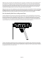
INSTALLATION, OPERATING AND SERVICE MANUAL TWIN TANK WATER SOFTENER WITH THE X-FACTOR CONTROL VALVE 7-TTLX-150 7-TTFESLX-60 7-TTLX-200 7-TTFESLX-90 7-TTLX-300 7-TTFESLX-120 7-TTLX-400 7-TTFESLX-180 7-TTLX-600 Congratulations on purchasing your new Lancaster Water Softener. This unit is designed to give you many years of trouble free service. When installed in accordance with the following instructions and if given reasonable care, clear-soft water will be the result. For servicing and future inspection SXUSRVHVSOHDVH¿OHWKLVERRNOHWZLWK\RXULPSRUWDQWGRFXPHQWV ,QWKHHYHQWWKDW\RXQHHGDVVLVWDQFHIRUVHUYLFLQJ\RXUZDWHUVRIWHQHUSOHDVH¿UVWFRQWDFWWKH professional contractor who installed the system. PAGE 1 TABLE OF CONTENTS -RE6SHFL¿FDWLRQV......................................................................................................................... Pre-Installation Review ................................................................................................................. General Installation and Service Warnings .................................................................................. Bypass Valve Operation ............................................................................................................... Installation Instructions, Diagrams ................................................................................................ Placing Softener into Service ....................................................................................................... General Operation ........................................................................................................................ Set Time of Day ............................................................................................................................ Adjust Hardness, Days Between Regenerations or Time of Regeneration .................................. Low Battery.................................................................................................................................... Contact Screen Programming ...................................................................................................... 6SHFL¿FDWLRQV ............................................................................................................................... Parts Diagrams ............................................................................................................................. Service Instructions ...................................................................................................................... Troubleshooting ............................................................................................................................ JOB SPECIFICATIONS MODEL NO. INSTALLATION DATE SERIAL NUMBER INSTALLER NAME PHONE ADDRESS WATER TEST AT TIME OF INSTALLATION Hardness CaCo3 (gpg) Other: Iron (ppm) pH SIZING INFORMATION All Water is Softened Except: Rear Hose Bib Other Front Hose Bib Kitchen Cold Toilets All Cold The average family uses 50 gallons per person daily for all water uses in the home. Daily Water Usage (Gallons/Person) x Family Size (Number of people in family) = Total Gallons Per Day x Grains Per Gallon of hardness (Note: Add 4 grains per gallon of hardness for each ppm iron for total compensated hardness) = Total Grains per Day PAGE 2 2 3 3 4 5 6 6 7 7 8 8 9 10-18 19-27 28-31 PRE-INSTALLATION REVIEW WATER QUALITY: If sand or sediment is present in the water VXSSO\ D VHGLPHQW ¿OWHU VKRXOG EH LQVWDOOHG DKHDG RI WKH ZDWHU softener. Your water softener has been designed to adequately reduce hardness from levels up to 100 grains per gallon. Ferrous bicarbonate iron levels up to 0.5 ppm can also be reduced. This is iron that is dissolved in water and not visible to the eye in a freshly drawn sample. After standing in contact with air, the ferrous iron will become oxidized to the ferric state and start to precipitate as a reddish EURZQÀRF,WFDQEHVHHQDQGPD\FDXVHGLVFRORUHGZDWHU$LUPXVW not come in contact with water until after it has passed through the water softener. In some cases, additional treatment equipment may be needed to treat water having special characteristics, such as: ferric hydroxide iron, iron bacteria, low pH, tastes and odors, etc. Consult your dealer if you have any questions. This water softener is not to be used for treating water that is microbiologically unsafe or of unknown quality without adequate disinfection before or after treatment. WATER PRESSURE: A minimum of 20 pounds of water pressure (psi) is required for regeneration. Maximum 100 psi. CAUTION: the softener cannot be subject to a vacuum due to loss of pressure VXFKDVDZDWHUPDLQEUHDNRUVXEPHUVLEOHZHOOSXPSFKHFNYDOYH failure). WATER TEMPERATURE: The range of water temperature is 35°F to 100°F. DO NOT install any water softener with less than 10 feet of piping between its outlet and the inlet of a water heater. AMBIENT TEMPERATURE: DO NOT locate softener where it or LWVFRQQHFWLRQVLQFOXGLQJWKHGUDLQDQGRYHUÀRZOLQHVZLOOHYHUEH subject to room temperatures under 33°F. ELECTRICITY: An uninterrupted 120 volt 60Hz source is required. Make sure electrical source is not on a timer or switch. All electrical connections must be connected according to local codes. The plug-in transformer is for dry locations only. Surge protection is recommended with all electrical connections. DRAIN: All plumbing should be done in accordance with local plumbing codes. The distance between the drain and the water softener should be as short as possible. The pipe size for the drain line should be a minimum of 1/2” (inside diameter of pipe). SOFTENING: It is recommended that the softener be installed to soften both the hot and cold water supply. A separate hard water IDXFHW PD\ EH SOXPEHG IRU GULQNLQJ SXUSRVHV LI GHVLUHG 2XWVLGH faucets should be left on hard water. BYPASS: A bypass valve (optional accessory) should be installed so that water will be available if it should be necessary to shut off the pressure in order to service the softener. GENERAL INSTALLATION AND SERVICE WARNINGS Do not use Vaseline, oils, other hydrocarbon lubricants or spray VLOLFRQHDQ\ZKHUH$VLOLFRQHOXEULFDQWPD\EHXVHGRQEODFNRULQJV but is not necessary. The nuts and caps are designed to be unscrewed or tightened by hand or with the special plastic wrench. If necessary a pliers can be used to unscrew the nut or cap. Do not use a pipe wrench to tighten or loosen nuts or caps. Do not place a screwdriver in the slots on caps and/or tap with a hammer. 'RQRWXVHSLSHGRSHRURWKHUVHDODQWVRQWKUHDGV8VH7HÀRQWDSH RQWKHWKUHDGHGLQOHWRXWOHWDQGGUDLQ¿WWLQJV7HÀRQWDSHLVQRW necessary on the nut connection or caps because of o-ring seals. After completing any valve maintenance involving the drive assembly or the drive cap assembly and pistons unplug power VRXUFHMDFNIURPWKHSULQWHGFLUFXLWERDUGEODFNZLUHDQGSOXJEDFN in or press and hold NEXT and REGEN buttons for 3 seconds. This resets the electronics and establishes the service piston position. 7KHGLVSOD\VKRXOGÀDVKDOOZRUGLQJWKHQÀDVKWKHVRIWZDUHYHUVLRQ and then reset the valve to the service position. All plumbing should be done in accordance with local plumbing codes. The pipe size for the drain line should be a minimum of ½”. %DFNZDVKÀRZUDWHVLQH[FHVVRIJSPOSPRUOHQJWKLQ excess of 20’ (6.1m) require ¾” drain line. Solder joints near the drain must be done prior to connecting the GUDLQOLQHÀRZFRQWURO¿WWLQJ/HDYHDWOHDVW´EHWZHHQWKHGUDLQ OLQHFRQWURO¿WWLQJDQGVROGHUMRLQWVZKHQVROGHULQJSLSHVWKDWDUH FRQQHFWHGRQWKHGUDLQOLQHFRQWURO¿WWLQJ)DLOXUHWRGRWKLVFRXOG FDXVHLQWHULRUGDPDJHWRWKHGUDLQOLQHÀRZFRQWURO¿WWLQJ :KHQDVVHPEOLQJWKHLQVWDOODWLRQ¿WWLQJSDFNDJHLQOHWDQGRXWOHW FRQQHFWWKH¿WWLQJWRWKHSOXPELQJV\VWHP¿UVWDQGWKHQDWWDFKWKH nut, split ring and o-ring. Heat from soldering or solvent cements may damage the nut, split ring or o-ring. Solder joints should be cool and solvent cements should be set before installing the nut, split ring and o-ring. Avoid getting primer and solvent cement on any part of the o-rings, split rings, bypass valve or control valve. Plug into an electrical outlet. Note: All electrical connections must be connected according to local codes. (Be certain the outlet is uninterrupted.) Install grounding strap on metal pipes. 7KLVJODVV¿OOHG1RU\O1 (or equivalent) fully automatic control valve is designed as the primary control center to direct and regulate all F\FOHVRIDZDWHUVRIWHQHURU¿OWHU The control valve is compatible with a variety of regenerants and UHVLQFOHDQHUV7KHFRQWUROYDOYHLVFDSDEOHRIURXWLQJWKHÀRZRI ZDWHULQWKHQHFHVVDU\SDWKVWRUHJHQHUDWHRUEDFNZDVKZDWHU WUHDWPHQWV\VWHPV7KHLQMHFWRUUHJXODWHVWKHÀRZRIEULQHRU RWKHUUHJHQHUDQWV7KHFRQWUROYDOYHUHJXODWHVWKHÀRZUDWHVIRU EDFNZDVKLQJULQVLQJDQGWKHUHSOHQLVKLQJRIWUHDWHGZDWHULQWRD UHJHQHUDQWWDQNZKHQDSSOLFDEOH 7KHFRQWUROYDOYH¿WWLQJVDQGRUE\SDVVDUHGHVLJQHGWR accommodate minor plumbing misalignments but are not designed to support the weight of a system or the plumbing. Control valve installation is made easy because the distributor WXEHFDQEHFXWò´DERYHWRò´EHORZWKHWRSRIWDQNWKUHDG7KH distributor tube is held in place by an o-ring seal and the control YDOYHDOVRKDVDED\RQHWORFNIHDWXUHIRUXSSHUGLVWULEXWRUEDVNHWV HYDROCARBONS SUCH AS KEROSENE, BENZENE, GASOLINE, ETC., MAY DAMAGE PRODUCTS THAT CONTAIN O-RINGS OR PLASTIC COMPONENTS. EXPOSURE TO SUCH HYDROCARBONS MAY CAUSE THE PRODUCTS TO LEAK. DO NOT USE THE PRODUCT(S) CONTAINED IN THIS DOCUMENT ON WATER SUPPLIES THAT CONTAIN HYDROCARBONS SUCH AS KEROSENE, BENZENE, GASOLINE, ETC. The power adapter comes with a 15 foot power cord and is designed for use with the control valve. The power adapter is for dry location use only. The control valve remembers all settings until the battery power is depleted if the power goes out. After the battery power is depleted, the only item that needs to be reset is the time of day; other values are permanently stored in the nonvolatile memory. The control valve battery is not rechargeable but is replaceable. THIS WATER METER SHOULD NOT BE USED AS THE PRIMARY MONITORING DEVICE FOR CRITICAL OR HEALTH EFFECT APPLICATIONS No user serviceable parts are on the PC board, the motor or the power adapter. The means of disconnection from the main power supply is by unplugging the power adapter from the wall. PAGE 3 BYPASS VALVE The bypass valve is typically used to isolate the control valve from the plumbing system’s water pressure in order to perform control valve repairs or maintenance. The X-Factor bypass valve is particularly unique in the water treatment industry due to its versatility DQGVWDWHRIWKHDUWGHVLJQIHDWXUHV7KH´IXOOÀRZE\SDVVYDOYHLQFRUSRUDWHVIRXUSRVLWLRQVLQFOXGLQJDGLDJQRVWLFSRVLWLRQWKDW DOORZVVHUYLFHSHUVRQDOWRZRUNRQDSUHVVXUL]HGV\VWHPZKLOHVWLOOSURYLGLQJXQWUHDWHGE\SDVVHGZDWHUWRWKHIDFLOLW\RUUHVLGHQFH,WV completely non-metallic, all-plastic design allows for easy access and serviceability without the need for tools. 7KHE\SDVVERG\DQGURWRUVDUHJODVV¿OOHG1RU\O®RUHTXLYDOHQWDQGWKHQXWVDQGFDSVDUHJODVV¿OOHGSRO\SURS\OHQH$OOVHDOVDUH self-lubricating EPDM to help prevent valve seizing after long periods of non-use. Internal o-rings can easily be replaced if service is required. The bypass consists of two interchangeable plug valves that are operated independently by red arrow-shaped handles. The handles LGHQWLI\WKHÀRZGLUHFWLRQRIWKHZDWHU7KHSOXJYDOYHVHQDEOHWKHE\SDVVYDOYHWRRSHUDWHLQIRXUSRVLWLRQV OPERATION: 1. Normal Operation Position: The inlet and outlet KDQGOHVSRLQWLQWKHGLUHFWLRQRIÀRZLQGLFDWHGE\WKH HQJUDYHG DUURZV RQ WKH FRQWURO YDOYH :DWHU ÀRZV through the control valve during normal operation and this position also allows the control valve to isolate the media bed during the regeneration cycle. VHH¿JXUH 1) 2. Bypass Position: The inlet and outlet handles point to the center of the bypass, the control valve is isolated from the water pressure contained in the plumbing system. Untreated water is supplied to the plumbing system. VHH¿JXUH ¿JXUH ¿JXUH ¿JXUH ¿JXUH 3. Diagnostic Position: The inlet handle points in WKH GLUHFWLRQ RI ÀRZ DQG WKH RXWOHW KDQGOH SRLQWV WR the center of bypass valve, system water pressure is allowed to the control valve and the plumbing system while not allowing water to exit from the control valve to the plumbing. VHH¿JXUH 4. Shut Off Position: The inlet handle points to the center of the bypass valve and the outlet handle SRLQWV LQ WKH GLUHFWLRQ RI ÀRZ WKH ZDWHU LV VKXW RII to the plumbing system. If water is available on the outlet side of the softener it is an indication of water bypass around the system (i.e. a plumbing connection somewhere in the building bypasses the system). VHH¿JXUH 7KHZRUNLQJSDUWVRIWKHE\SDVVYDOYHDUHWKHURWRUDVVHPEOLHVWKDWDUHFRQWDLQHGXQGHUWKHE\SDVVYDOYHFDSV%HIRUHZRUNLQJRQWKH URWRUVPDNHVXUHWKHV\VWHPLVGHSUHVVXUL]HG7XUQWKHUHGDUURZVKDSHGKDQGOHVWRZDUGVWKHFHQWHURIWKHE\SDVVYDOYHDQGEDFN several times to ensure rotor is turning freely. The nuts and caps are designed to be unscrewed or tightened by hand. If necessary a pliers or the service spanner wrench can be used to unscrew the nut or cap. Do not use a pipe wrench to tighten or loosen nuts or caps. Do not place screwdriver in slots on caps and/or tap with a hammer. Refer to page 19 for bypass valve parts diagram and service spanner wrench information. To access the rotor, unscrew the cap and lift the cap, rotor and handle out as one unit. Twisting the unit as you pull it out will help to remove it more easily. There are three o-rings: one under the rotor cap, one on the rotor stem and the rotor seal. Replace worn o-rings. Clean rotor. Reinstall rotor. When reinstalling the red arrow handles be sure that: 1. The handle pointers are lined up with the control valve body arrows, and the rotor seal o-ring and retainer on both rotors face to the right when being viewed from the front of the control valve; or 2. Arrows point toward each other in the bypass position. Since the handles can be pulled off, they could be accidentally reinstalled 180° from their correct orientation. To install the red arrow KDQGOHVFRUUHFWO\NHHSWKHKDQGOHVSRLQWHGLQWKHVDPHGLUHFWLRQDVWKHDUURZVHQJUDYHGRQWKHFRQWUROYDOYHERG\ZKLOHWLJKWHQLQJWKH bypass valve caps. PAGE 4 INSTALLATION INSTRUCTIONS (All electrical & plumbing should be done in accordance to all local codes) 3ODFHWKHVRIWHQHUZKHUH\RXZDQWWRLQVWDOOLWPDNLQJ VXUHLWLVRQDFOHDQOHYHODQG¿UPEDVH 2. Do all necessary plumbing (inlet to inlet, outlet to outlet, DQGGUDLQOLQHWRGUDLQ7KHFRQWUROYDOYH¿WWLQJVDQGRU bypass are designed to accommodate minor plumbing misalignments but are not designed to support the weight of a system or the plumbing. :KHQDVVHPEOLQJWKHLQVWDOODWLRQ¿WWLQJSDFNDJHLQOHW DQG RXWOHW FRQQHFW WKH ¿WWLQJ WR WKH SOXPELQJ V\VWHP ¿UVW DQG WKHQ DWWDFK WKH QXW VSOLW ULQJ DQG RULQJ +HDW from soldering or solvent cements may damage the nut, split ring or o-ring. Solder joint should be cool and solvent cements should be set before installing the nut, split ring and o-ring. Avoid getting primer and solvent cement on any part of the o-rings, split rings, bypass valve or control valve. 4. A jumper ground wire should be installed between the inlet and outlet pipe whenever the metallic continuity of a water distribution piping system is interrupted. Install grounding strap on metal pipes. 5. The drain connection may be made using either 5/8” polytube (see below) or a 3/4” female adapter. The polytube insert is shipped attached to the drain line HOERZ¶V ORFNLQJ FOLS 3UHVV WKH LQVHUW LQWR WKH GUDLQ OLQH tubing (tubing not provided). Loosen the nut of the drain line elbow. Press the 5/8” polytube with insert into the GUDLQ OLQH HOERZ XQWLO LW VHDWV RQ WKH EDFN RI WKH ¿WWLQJ Tighten the nut. If soldering, joints near the drain must be GRQHSULRUWRFRQQHFWLQJWKHGUDLQOLQHÀRZFRQWURO¿WWLQJ /HDYHDWOHDVW´EHWZHHQWKHGUDLQOLQHFRQWURO¿WWLQJDQG solder joints when soldering pipes that are connected on WKHGUDLQOLQHFRQWURO¿WWLQJ)DLOXUHWRGRWKLVFRXOGFDXVH LQWHULRUGDPDJHWRWKHGUDLQOLQHÀRZFRQWURO¿WWLQJ1HYHU insert a drain line into a drain, sewer line, or trap. Always allow an air gap between the drain line and the wastewater WRSUHYHQWWKHSRVVLELOLW\RIVHZDJHEHLQJEDFNVLSKRQHG into the softener. 7KHEULQHUH¿OOÀRZFRQWURODVVHPEO\LVLQVWDOOHGLQDQ HDV\ WR DFFHVV UH¿OO HOERZ ORFDWHG RQ WRS RI WKH FRQWURO YDOYH7KHUH¿OOÀRZFRQWURODVVHPEO\LVDWWDFKHGWRWKH FRQWUROYDOYHZLWKDORFNLQJFOLS7KHORFNLQJFOLSDOORZVWKH elbow to rotate 270 degrees so the outlet can be oriented WRZDUGVWKHEULQHWDQN 7. Connect the brine line polytubing found with the brine WDQN WR WKH EULQH FRQQHFWLRQ RQ WKH FRQWURO YDOYH 7KH FRQWURO YDOYH KDVDVWDQGDUGUH¿OO HOERZ WRZKLFK D´ ÀH[LEOHWXEHFDQEHFRQQHFWHGVHH below. One polytube LQVHUW LV VKLSSHG RQ WKH EULQH OLQH HOERZ¶V ORFNLQJ FOLS 5HPRYHWKLVZKLWHSRO\WXEHLQVHUWDQGUHSODFHWKHORFNLQJ clip. The second polytube insert is taped to the top of WKH EULQH ZHOO FDS LQ WKH EULQH WDQN 3UHVV WKH SRO\WXEH inserts into each end of the provided brine tubing, press WKH SRO\WXEH ZLWK LQVHUW LQWR WKH QXW RQ WKH EULQH ¿WWLQJ Tighten nut securely to create a pressure tight connection. The nut, gripper and retainer sleeve is a three-piece assembly that can come apart from the elbow body. Parts must be reassembled exactly as shown to function properly. If the nut is completely removed from the body, slip the nut, plastic gripper and retainer sleeve on to the WXEH WKHQ WLJKWHQ RQ WR WKH ¿WWLQJ 0DNH VXUH WKH ÀRRU LV FOHDQ EHQHDWK WKH EULQH WDQN DQG WKDW LW LV OHYHO DQG VPRRWK ,QVWDOO EULQH WXELQJ WR WKH EULQH WDQN XVLQJ WKH above instructions. 8. A 1/2” (inside diameter, not provided) gravity drain line VKRXOGEHFRQQHFWHGWRWKHRYHUÀRZ¿WWLQJRQWKHVLGHRI WKHEULQHWDQN7KLVRYHUÀRZLVLQFDVHRIDPDOIXQFWLRQLQ the brine shut off. If the unit is installed where water may ÀRZLQWKHHYHQWRIDQRYHUÀRZDQGFDXVHZDWHUGDPDJH FRQQHFWDOHQJWKRIÀH[LEOHWXELQJDQGUXQWRDGUDLQEHORZ WKHOHYHORIWKHRYHUÀRZ(Do not connect the tubing to the drain line on the control valve. Do not run tubing DERYHRYHUÀRZKHLJKWDWDQ\SRLQW 2nd Tank Connection Port Treated Water Outlet BRINE LINE FITTING CONNECTIONS In/Out Head DRAIN LINE FITTING CONNECTION USING 5/8" POLY TUBE PAGE 5 2nd Tank Connection Port Untreated Water Inlet Control Valve PLACING SOFTENER INTO SERVICE 'RQRWDGGVDOWWRWKHEULQHWDQN\HW'RQRWSOXJWKHWUDQVIRUPHULQWRWKHUHFHSWDFOH\HW0DNHVXUHLQOHWDQGRXWOHWYDOYHVDUHWRWKHLU closed positions. If using optional bypass, place in bypass position. Turn on main water supply. Open a cold water faucet. This will clear the line of any debris (solder, pipe dope, etc.) that may be in the line. Let water run at faucet for a couple minutes, or until clear. Turn RIIIDXFHW0DQXDOO\DGGòJDOORQVRIZDWHUWRWKHEULQHWDQN1RZSOXJWKHWUDQVIRUPHULQWRDYROWUHFHSWDFOHEHFHUWDLQWKH receptacle is uninterrupted). Within 5 seconds the control display and buttons will illuminate and the time of day screen will appear. Press and hold the Wait until display reads BACKWASH and numbers start counting down. Momentarily press REGEN again. Valve is now in the REGENERANT DRAW position. Momentarily press REGEN again. Valve is now in the BACKWASH position. REGEN button for approximately 5 seconds until the motor starts. If using optional bypass SLOWLY turn bypass valve to DIAGNOSTIC position (6HH¿JXUHRQSDJH) or slowly open inlet valve to allow water to slowly enter Softener. :KHQZDWHULVÀRZLQJVWHDGLO\WRGUDLQZLWKRXWWKHSUHVHQFHRIDLUPRPHQWDULO\SUHVV REGEN again. Display will read RINSE. Open the outlet valve of the softener, or if using optional bypass place to NORMAL OPERATION MODE (VHH¿JXUHRQSDJH $OORZFRQWUROWR¿QLVKWKHRINSE cycle. Allow the control to automatically advance to the FILL position. Close inlet valve WKHQUHSHDWDERYHVWHSVIRUWKHVHFRQGVRIWHQHUWDQN:KHQWKHFILL cycle is reached, press REGEN to advance to the SOFTENING position.1RZORDGWKHEULQHWDQNZLWKVDOW6RODU6DOWLVUHFRPPHQGHG7KHEULQHWDQNVDOWOHYHOVKRXOGEHFKHFNHGHYHU\ FRXSOHRIZHHNVWRGHWHUPLQHVDOWXVDJH.HHSLQJWKHEULQHWDQNVDOWOHYHODWOHDVWIXOOLVUHFRPPHQGHG SANITIZING: Use 2 oz. of 5 ¼% unscented household chlorine bleach for each cubic foot of resin. Pour bleach directly into the 4” GLDPHWHUZKLWHEULQHZHOOORFDWHGLQVLGHWKHEULQHWDQN3UHVVDQGKROGWKH REGEN for 5 - 6 seconds until the motor starts running. Allow V\VWHPWRFRPSOHWHWKHUHJHQHUDWLRQDXWRPDWLFDOO\&KHFNIRURWKHUORFDODQGVWDWHFRGHVZKLFKPD\DOVRVSHFLI\VDQLWDWLRQPHWKRGV 1RWH7KH¿UVWVWHSRIWKHUHJHQHUDWLRQSURFHVVLVWR¿OOWKHEULQHWDQNZLWKWKHSURSHUDPRXQWRIZDWHU7KHEULQHWDQNZLOO RQO\KDYHDYHU\VOLJKWDPRXQWRIZDWHULQLWDIWHUWKHUHJHQHUDWLRQF\FOHVDUHFRPSOHWHG GENERAL OPERATION 1RWH$VDQHQHUJ\VDYLQJIHDWXUHWKHFRQWUROZLOODXWRPDWLFDOO\WXUQRIIDOO62/,'%/8(RU62/,'*5((1GLVSOD\ LOOXPLQDWLRQDQGNH\SDGLOOXPLQDWLRQDIWHUDERXWPLQXWHVRIWKHODVWNH\SDGEXWWRQSXVK$Q\IXUWKHUNH\SDGWRXFKZLOO FDXVHWKHUHLOOXPLQDWLRQRIWKHGLVSOD\DQGNH\SDGDQGUHDFWLYDWHNH\SDGFRQWURO User Displays :KHQWKHV\VWHPLVLQQRUPDOVHUYLFHPRGHRQHRIXSWR¿YH available User Displays will be shown. Pressing NEXT will alternate between the following displays: &XUUHQWWLPHRIGD\ 7UHDWHGZDWHUÀRZUDWH 6HUYLFHFRQWDFWQDPHDQGSKRQHQXPEHULIHQWHUHG 5HPDLQLQJ&DSDFLW\RIWUHDWHGZDWHUDYDLODEOH button while in the Capacity Remaining or Pressing the Days Remaining displays will decrease the capacity remaining in ten gallon increments or the days remaining in one day increments. To clear the Service Call reminder, press the and buttons simultaneously while the number and banner text screen is displayed. If the system has called for a regeneration that will occur at the preset time of regeneration, the words REGEN TODAY will alternate with the header on the display. Utilizing the control valve’s built-in water meter, a water drop ÀDVKHVRQWKHGLVSOD\ZKHQZDWHULVEHLQJWUHDWHGLHZDWHULV ÀRZLQJWKURXJKWKHV\VWHP A 'URSZLOOÀDVKZKLOHZDWHU is being treated. A NEXT Contact Screen NEXT A NEXT PAGE 6 SET TIME OF DAY Current time of day needs to be entered during initial installation, and adjusted when daylight saving time begins or ends. If an extended power outage occurs and depletes the on-board non-rechargeable coin cell battery, when power resumes the time of day should be reset and battery replaced. STEP 1 STEP 1 – Press STEP 2 STEP 2 - Current Time (hour): Set the hour of the day using after 12. Press NEXT to go to Step 3. STEP 3 STEP 3 - Current Time (minutes): Set the minutes of the day using NEXT to exit Set Time of Day. Press REGEN to return to previous step. CLOCK or buttons. AM/PM toggles or buttons. Press RETURN TO NORMAL MODE ADJUST HARDNESS, DAYS BETWEEN REGENERATIONS, OR TIME OF REGENERATION STEP 1 STEP 1 - Press STEP 2 STEP 2 – Hardness: Set the amount of hardness in grains of hardness as calcium carbonate per gallon using the or buttons. The default is 20 with value ranges from 1 to 150 in 1 grain increments. Note: The grains per gallon can be increased if soluble iron needs to be reduced. Press NEXT to go to step 3. Press REGEN to exit Installer Display Settings. STEP 3 STEP 3 – Day Override: Set the maximum number of days between regenerations. If value set to “OFF”, regeneration initiation is based solely on volume used. If value is set as a number (allowable UDQJHIURPWRDUHJHQHUDWLRQLQLWLDWLRQZLOOEHFDOOHGIRURQWKDWGD\HYHQLIVXI¿FLHQWYROXPHRI water were not used to call for a regeneration. Set Day Override using or buttons: QXPEHURIGD\VEHWZHHQUHJHQHUDWLRQWRRU ³2))´ Press STEP 4 NEXT NEXT and simultaneously for 3 seconds to access Installer Display Settings. to go to step 4. Press STEP 4 – Press NEXT REGEN to return to previous step. to go to Step 5. Press RETURN TO NORMAL MODE PAGE 7 REGEN to return to previous step. LOW BATTERY A non-rechargeable coin cell battery is located on the circuit board, used only to maintain the time of day during power outages (all other information will be stored in memory no matter how long the power outage). The screen displays LOW BATTERY when the battery needs to be replaced. The screen will remain illuminated solid blue when LOW BATTERY is GLVSOD\HG,QLWLDOO\/2:%$77(5<GLVSOD\ZLOODOWHUQDWHZLWKWKH8VHUGLVSOD\¿QDOO\GLVSOD\LQJRQO\/2:%$77(5<8VHU displays are still accessible by pressing NEXT . CONTACT SCREEN PROGRAMMING STEP 1 STEP 1 - Press Settings. NEXT and simultaneously for 3 seconds to access Installer Display STEP 2 - Press NEXT to go to step 3. STEP 3 - Press NEXT to go to step 4. STEP 2 STEP 3 STEP 4 From Step 4, Press and hold both the and banner text. CLOCK and Phone Number - Set phone number using the or REGEN to the next digit. Press to return to previous digit. button to change phone number arrow. Press NEXT to forward Banner Text - Set the banner text up to a maximum of 44 characters. Use the or to select letters of the alphabet, numbers, ampersand (&), or a space in the banner text. Press NEXT to forward to the next character or to exit the Installer Display Settings. PAGE 8 X FACTOR SERIES TTLX SPECIFICATIONS MODEL NUMBER 7-TTLX-150 7-TTLX-200 7-TTLX-300 7-TTLX-400 7-TTLX-600 Service Flow (GPM) at 15 PSI Pressure Drop 13 17 16 18 19 8 x 44 10 x 40 10 x 54 12 x 48 14 x 65 Resin; Cu. Ft. HDFKWDQN 0.75 1 1.5 2 3 %ULQH7DQN6L]H(inches) 15 x 17 x 36 15 x 17 x 36 15 x 17 x 36 18 x 40 24 Dia x 50 %ULQH7DQN&DSDFLW\ Lbs NaCl 275 275 275 450 900 Drain Line Flow Control; GPM 1.0 1.7 1.7 2.7 4.2 Brine Line (Re-Fill)Flow Control; GPM 0.5 0.5 0.5 0.5 0.5 1C - Violet 1E - White 1E - White 1F - Blue 1H - Green 5HVLQ7DQN6L]H Diameter x Height (inches) Injector; color X FACTOR SERIES TTLXC SPECIFICATIONS MODEL NUMBER 7-TTLXC-150 Service Flow (GPM) at 15 PSI Pressure Drop 18 5HVLQ7DQN6L]H Diameter x Height (inches) Resin; Cu. Ft. HDFKWDQN 10 x 35 0.75 Cabinet Size (including top cover); W” x L” x H” 13.5 x 22.5 x 44 Cabinet Capacity (with grid); Lbs NaCl 225 Drain Line Flow Control; GPM 1.7 Brine Line (Re-Fill) Flow Control; GPM 0.5 Injector; color 1E - White PAGE 9 SOFTENER ASSEMBLY 1 Dwg. No. 2 Description 2 D1203 3,4,5 1 Top Distributor 2 7DQN3LSH&RQQHFWRU$VV\IRU0RGHO77/; 2 FG1040VT, D1130-12 Ft. (cut for 40 in.), R-DIP1050 7DQN3LSH&RQQHFWRU$VV\IRU0RGHO77/; 2 FG1054VT, D1130-12 Ft. (cut for 54 in.), R-DIP1050 7DQN3LSH&RQQHFWRU$VV\IRU0RGHO77/; 2 FG1248VT, D1130-12 Ft. (cut for 48 in.), R-DIP1050 7DQN3LSH&RQQHFWRU$VV\IRU0RGHO77/; 2 FG1465VT, D1130-12 Ft. (cut for 65 in.), R-DIP1050 7DQN3LSH&RQQHFWRU$VV\IRU0RGHO77/; 2 FG844VT, D1130-12 Ft. (cut for 44 in.), R-DIP1050 A4074 (3/4 Cu. Ft. = 39 LBS) 6 6 Qty LXCV1TT (detailed components shown in this manual) 0HWHUHG&RQWURO9DOYH7ZLQ7DQN 1 3 4 5 Order No. Ion Exchange Resin for Model 7-TTLX-150 2 A4074 (1 Cu. Ft. = 52 LBS) Ion Exchange Resin for Model 7-TTLX-200 2 A4074 (1 1/2 Cu. Ft. = 78 LBS) Ion Exchange Resin for Model 7-TTLX-300 2 A4074 (2 Cu. Ft. = 104 LBS) Ion Exchange Resin for Model 7-TTLX-400 2 A4074 (3 Cu. Ft. = 156 LBS) Ion Exchange Resin for Model 7-TTLX-600 2 BRINE TANK ASSEMBLY Dwg. No. 1 2 3 Order No. Description L56-40A [%ULQH7DQNZLWK&RYHUIRU0RGHO77/; 1 G2162 [%ULQH7DQNZLWK&RYHUIRU0RGHO77/; 1 H1031 4x28 Slotted Brine Well for Model 7-TTLX-150, -200, -300 1 H1042 4x46 Slotted Brine Well for Model 7-TTLX-600 1 5 H7016 4 inch Brine Well Cap for Model 7-LX-150, -200, -300, -600 1 4 3/8” Brine Valve Assembly XVLQJ´[´ORQJDLUFKHFNDVV\IRU0RGHO77/; XVLQJ´[´ORQJDLUFKHFNDVV\IRU0RGHO77/; 1 4 4740 5 H1018 7ZR3LHFH2YHUÀRZ6HW 1 1640N Nylon Screw (only for Model 7-TTLX-600) 1 6785N Nylon Nut (only for Model 7-TTLX-600) 1 H1023 3/8”O.D.x6 Ft. Poly Tubing 1 6 7 L56-50A 24 x 50 %ULQH7DQN$VV\ Qty 3 6 1 2 4740 BRINE VALVE ASSEMBLY 1 3 7 2 3 J7952 15 x 17 x 36 %ULQH7DQN$VV\ 4 Dwg No. Order No. Description 1 H4600 3/8” Safety Brine Valve 1 2 10151 Pin 1 3 H4640-9.5 Float Assembly 1 4 H4500-48 $LU&KHFN$VVHPEO\XQFXWOHQJWK VHHEULQHWDQNDVV\IRUFXWOHQJWK PAGE 10 Qty 1 X-FACTOR FRONT COVER AND DRIVE ASSEMBLY Drawing No. 1 2 3 4 5 6 Order No. V3692-02LW V3107-01 V3106-01 V3757LP-BOARD V3110 V3109 When replacing the battery, align positives and push down to fully seat. Description LP Front Cover Assembly Motor 'ULYH%UDFNHW6SULQJ&OLS PC Board Drive Gear 12x36 Drive Gear Cover Correct Battery Orientation Quantity 1 1 1 1 3 1 Battery replacement is 3 volt lithium coin cell type 2032. Battery Fully Seated 4 AC Adapter (Not shown) Order No. V3186 Supply Voltage 120V AC Supply Frequency 60 Hz Output Voltage 12V AC Output Current 500 mA 1 5 6 2 3 After completing any valve maintenance involving the drive assembly or the drive cap assembly and pistons, unplug SRZHUVRXUFHMDFNIURPWKHSULQWHGFLUFXLWERDUGEODFNZLUHDQGSOXJEDFNLQRUSUHVVDQGKROG NEXT and REGEN buttons IRUVHFRQGV7KLVUHVHWVWKHHOHFWURQLFVDQGHVWDEOLVKHVWKHVHUYLFHSLVWRQSRVLWLRQ7KHGLVSOD\VKRXOGÀDVKWKH software version and then reset the valve to the service position. PAGE 11 DRIVE CAP ASSEMBLY, DOWNFLOW PISTON, REGENERANT PISTON AND SPACER STACK ASSEMBLY Drawing No. Order No. Description 1 V3005 6SDFHU6WDFN$VVHPEO\ 1 2 V3004 Drive Cap Assy 1 3 V3178LP %DFN3ODWH 1 4 V3011 3LVWRQ'RZQÀRZ$VV\ 1 5 V3174 Regenerant Piston 1 6 V3135 O-ring 228 1 7 V3180 O-ring 337 1 8 V3105 O-ring 215 (Distributor Tube) 1 Not Shown V3001 %RG\$VV\'RZQÀRZ 1 After completing any valve maintenance involving the drive assembly or the drive cap assembly DQGSLVWRQVXQSOXJSRZHUVRXUFHMDFN IURPWKHSULQWHGFLUFXLWERDUGEODFN ZLUHDQGSOXJEDFNLQRUSUHVVDQG Qty Do not use Vaseline, oils, other hydrocarbon lubricants or spray silicone anywhere. A silicone lubricant may be XVHGRQEODFNRULQJVEXWLVQRWQHFHVVDU\ Avoid any type of lubricants, including silicone, on the clear lip seals. 3 2 hold NEXT and REGEN buttons for 3 seconds. This resets the electronics and establishes the service piston SRVLWLRQ7KHGLVSOD\VKRXOGÀDVKWKH software version and then reset the valve to the service position. 1 5 4 7 6 8 INJECTOR CAP, INJECTOR SCREEN, INJECTOR, PLUG AND O-RING Drawing No. 1 2 3 4 1 2 3 5 4 5 Not Shown Not Shown Order No. V3176 V3152 V3177-01 V3010-1Z V3010-1A V3010-1B V3010-1C V3010-1D V3010-1E V3010-1F V3010-1G V3010-1H V3010-1I V3010-1J V3010-1K V3170 V3171 Description INJECTOR CAP O-RING 135 INJECTOR SCREEN CAGE INJECTOR ASSY Z PLUG INJECTOR ASSY A BLACK INJECTOR ASSY B BROWN INJECTOR ASSY C VIOLET INJECTOR ASSY D RED INJECTOR ASSY E WHITE INJECTOR ASSY F BLUE INJECTOR ASSY G YELLOW INJECTOR ASSY H GREEN INJECTOR ASSY I ORANGE INJECTOR ASSY J LIGHT BLUE INJECTOR ASSY K LIGHT GREEN O-RING 011 O-RING 013 Qty 1 1 1 1 1 * * * The injector plug and the injector each contain one 011 (lower) and 013 (upper) o-ring. The nut and caps are designed to be unscrewed or tightened by hand or with the service spanner wrench (see page 19). If necessary a pliers can be used to unscrew the nut or cap. Do not use a pipe wrench to tighten or loosen nuts or caps. Do not place a screwdriver in slots on caps and/or tap with a hammer. PAGE 12 PAGE 13 1 2 3 4 5 6 8 9 7 10 Twin Transfer 5 6 14 11 4 10 13 12 15 18 19 7 2 1 16 20 17 21 22 Twin Transfer Drawing No. 1 2 3 4 5 6 7 8 9 10 11 12 13 14 15 16 17 18 19 20 21 22 NOT SHOWN NOT SHOWN NOT SHOWN NOT SHOWN NOT SHOWN Order No. V3470 V3724 V4005-01 V4029 V4015 V4014 V4036 V3105 V3180 V4016 V3031 V4023 V3287 V4006-01 V4011-01 V4012 V4013 V3264 V3110-01 V3262-01 V3592 V4049 V4043 V3151 V4055* V4017-01 D1400 Description SCREW BHC 1/4-20 X 1 SS WASHER FLAT SS 1/4 T1 TRANSFER CAP ASY O-RING 236 T1 TRANSFER SPRING T1 TRANSFER SPRING SUPPORT T1 ROTOR DISK ASY O-RING 215 (DISTRIBUTOR TUBE) O-RING 337 T1 TRANSFER SEAL T1 BODY SFT WTR REGEN T1 TRANSFER DRIVE SHAFT ASY O-RING 110 T1 TRANSFER DRIVE CAP ASY T1 TRANSFER DRIVE GEAR ASY T1 TRANSFER DRIVE GEAR AXLE T1 TRANSFER REDUCTION GEAR WS2H BYPASS REDUCTION GEARAXLE WS1 DRIVE REDUCING GEAR PLAIN WS1.5&2ALT/2BY REDUCGEARCVRASY SCREW #8-1 PHPN T-25 SS T1 COVER ASSEMBLY T1 TRANSFER MOTOR ASY WS1 NUT 1 QC TWIN TANK METER ASY T1 INTERCONNECT FITTING ASY 1191 IN/OUT HEAD Quantity 12 12 1 2 2 2 2 1 1 6 1 1 2 1 1 1 1 3 3 1 3 1 1 1 1 1 1 *THIS WATER METER SHOULD NOT BE USED AS THE PRIMARY MONITORING DEVICE FOR CRITICAL OR HEALTH EFFECT APPLICATIONS. REFILL FLOW CONTROL ASSEMBLY 4 3 8 2 Drawing No. Order No. Description Qty 1 H4615 (OERZ/RFNLQJ&OLS 1 2 H4614 Polytube insert 3/8” 1 3 H4612 Nut 3/8” 1 4 H4613 Elbow Cap 3/8” 1 5 V3163 0-ring 019 1 6 V3165-01* RFC Retainer Assy 1 7 V3182 RFC 1 8 V3330 Brine Elbow Assy w/RFC 3/8” 1 *Assembly includes V3182 RFC. 5 6 7 1 Water Flow Proper RFC orientation GLUHFWVUH¿OOZDWHUÀRZ towards the washer face with rounded edge and text. PAGE 14 V4017-01 TT Interconnect Fitting Assembly up to 10” tanks 1 4 2 3 Drawing No. 1 2 3 4 Order No. V3151 V3150 V3105 V4017 Description WS1 NUT 1" QUICK CONNECT WS1 SPLIT RING O-RING 215 T1 INTERCONNECT FITTING Quantity 4 4 4 2 V4052-01 TT Interconnect Fitting Assembly for 12” to 21” Tanks 4 1 3 5 cut to length 5 4 1 2 3 2 Drawing No. 1 2 3 4 5 Order No. V3151 V3150 V3105 V3352 V4052 Description WS1 NUT 1” QUICK CONNECT WS1 SPLIT RING O-RING 215 WS1 FITTING 1¼”&1½” PVC SOLVENT PIPE PVC SCH 80 1¼” X 2” Quantity 4 4 4 4 2 D1400 1191 In/Out Head Fitting Installation Instructions: ,QVWDOODWLRQ¿WWLQJVDUHGHVLJQHG to accommodate minor plumbing misalignments, but are not designed to support the weight of a system or the plumbing. 6OLGHQXWRQ¿UVWWKHQWKHVSOLWULQJ and o-ring. +DQGWLJKWHQWKHQXWRQO\ 7KH9WZLQWDQNFRQWUROYDOYH LQWHUFRQQHFWNLWFDQEHXVHGRQWDQNV XSWR´LQGLDPHWHUDQGLVSDFNHG in with control valve. If using 12” diameter tanks or larger order optional kit number V4052-01 twin tank control valve interconnect kit for 12” thru 21” diameter tanks. 1 2 Drawing No. 1 2 Order No. Description V3180 O-RING 337 V3105 O-RING 215 (DISTRIBUTOR TUBE) PAGE 15 Quantity 1 1 DRAIN LINE - 3/4” Dwg No. 1 2 3 4* 5 6* Order No. Description Qty H4615 (OERZ/RFNLQJ&OLS 1 V3194 Polytube insert 5/8 Option V3192 Nut ¾ Drain Elbow Option V3158 Drain Elbow ¾ Male 1 V3163 O-ring 019 1 V3159 DLFC Retainer Assy 1 V3162-007 DLFC 0.7 gpm for ¾ V3162-010 DLFC 1.0 gpm for ¾ One V3162-013 DLFC 1.3 gpm for ¾ DLFC V3162-017 DLFC 1.7 gpm for ¾ must V3162-022 DLFC 2.2 gpm for ¾ be V3162-027 DLFC 2.7 gpm for ¾ used 7 V3162-032 DLFC 3.2 gpm for ¾ V3162-042 DLFC 4.2 gpm for ¾ if ¾ V3162-053 DLFC 5.3 gpm for ¾ ¿WWLQJ V3162-065 DLFC 6.5 gpm for ¾ is V3162-075 DLFC 7.5 gpm for ¾ used V3162-090 DLFC 9.0 gpm for ¾ V3162-100 DLFC 10.0 gpm for ¾ *4 and 6 can be ordered as a complete assembly V3331 Drain Elbow and Retainer Assy 4 Water Flow Proper DLFC orientation GLUHFWVZDWHUÀRZWRZDUGV the washer face with rounded edge. 'RQRWXVHSLSHGRSHRURWKHUVHDODQWVRQWKUHDGV7HÀRQWDSHPXVWEHXVHGRQWKUHDGVRI´137FRQQHFWLRQXQOHVV using 5/8” polytubing). Do not use Vaseline, oils, other hydrocarbon lubricants or spray silicone anywhere. A silicone lubricant may be used on EODFNRULQJVEXWLVQRWQHFHVVDU\ INSTALLATION FITTING ASSEMBLIES Order No: V3007 (Standard) Description: Fitting 1” PVC Male NPT Elbow Assembly Drawing No. Order No. Description Drawing No. 1 2 3 4 Quantity 1 V3151 1XW´4XLFN&RQQHFW 2 2 V3150 Split Ring 2 3 V3105 O-Ring 215 2 V3149 Fitting 1 PVC Male NPT Elbow 2 4 Order No. V3191-01 (Optional) Description: Fitting Vertical Adapter Assembly Order No. V3151 V3150 V3105 V3191 Description Quantity 1XW´4XLFN&RQQHFW Split Ring O-Ring 215 Vertical Adapter 2 2 2 2 2 4 3 1 'RQRWXVHSLSHGRSHRURWKHUVHDODQWVRQWKUHDGV7HÀRQWDSHPXVWEHXVHGRQWKUHDGVRI´137FRQQHFWLRQ7HÀRQ tape is not necessary on the nut connection nor caps because of o-ring seals. The nut and caps are designed to be unscrewed or tightened by hand or with the service spanner wrench (see page 17). If necessary a pliers can be used to unscrew the nut or cap. Do not use a pipe wrench to tighten or loosen nuts or caps. Do not place a screwdriver in slots on caps and/or tap with a hammer. Do not use Vaseline, oils, other hydrocarbon lubricants or spray silicone anywhere. A silicone lubricant may be used on EODFNRULQJVEXWLVQRWQHFHVVDU\ PAGE 16 BYPASS VALVE (Order No. BP2000) Drawing No. 1 2 3 4 5 Order No. V3151 V3150 V3105 V3145 V3146 6 7 8 9 10 V3147 V3148 V3152 V3155 V3156 Description 1XW´4XLFN&RQQHFW Split Ring O-Ring 215 Bypass 1” Rotor Bypass Cap Qty 2 2 2 2 2 Bypass Handle Bypass Rotor Seal Retainer O-ring 135 O-ring 112 O-ring 214 2 2 2 2 2 SERVICE SPANNER WRENCH (Order No. V3193) Although no tools are necessary to assemble or disassemble the valve, the wrench (shown in various positions on the valve) may be purchased to aid in assembly or disassembly. Loosens Injector And Bypass Caps Loosens Drive Cap PAGE 17 OPTIONAL INSTALLATION FITTING ASSEMBLIES Order No: V3007-01 Description: Fitting ¾” & 1” PVC Solvent 90° Assembly Drawing No. Order No. 1 V3151 2 V3150 3 V3105 O-Ring 215 4 Quantity Drawing No. Order No. 1XW´4XLFN&RQQHFW 2 1 V3151 2 1XW´4XLFN Connect 2 Split Ring 2 V3150 Split Ring 2 3 V3105 O-Ring 215 2 Fitting ¾ Brass Sweat 2 Quantity Drawing No. Order No. 1XW´4XLFN&RQQHFW 2 1 V3151 Split Ring 2 2 V3150 2 3 V3105 O-Ring 215 2 Description Fitting ¾&1 PVC Solvent 90 V3189 Order No: V3007-03 Description: Fitting ¾” Brass Sweat Assembly Order No: V3007-02 Description: Fitting 1” Brass Sweat Assembly 2 4 V3188 Description Fitting 1 Brass Sweat Assembly 2 4 V3188-01 Do not install in California. Description Quantity Do not install in California. Order No: V3007-04* Description: Fitting 1” Plastic Male NPT Assembly Drawing No. Order No. 1 V3151 2 V3150 3 V3105 V3164 Fitting 1" Plastic Male NPT 4 Quantity Drawing No. Order No. 2 1 V3151 1XW´4XLFN&RQQHFW 2 Split Ring 2 2 V3150 Split Ring O-Ring 215 2 3 V3105 O-Ring 215 V3317 Fitting 1-¼" Plastic Male NPT Description 1XW´4XLFN&RQQHFW 2 Order No. V3007-07* Description: Fitting 1¼” & 1½” PVC Solvent Assembly Order No: V3007-05 Description: Fitting 1-¼” Plastic Male NPT Assembly 4 Description Drawing No. Quantity Order No. Description Quantity 1 V3151 1XW´4XLFN&RQQHFW 2 2 2 V3150 Split Ring 2 2 3 V3105 O-Ring 215 2 4 V3352 Fitting 1¼”&1½” PVC Solvent 2 2 4 4 4 1 1 1 2 2 2 3 3 3 1 NPT Order No: V3007-09* Description: Fitting 1¼” & 1½” Brass Sweat Assembly Drawing No. Order No. Description Quantity 1 V3151 1XW´4XLFN&RQQHFW 2 2 V3150 Split Ring 2 3 V3105 O-Ring 215 2 V3375 Fitting 1¼" & 1½" Brass Sweat 2 4 Order No. V3007-12 Description: Fitting 3/4" Brass SharkBite Assembly Drawing No. 1 2 3 4 Order No. V3151 V3150 V3105 V3628 4 1 1 Order No. V3007-13* Description: Fitting 1" Brass SharkBite Assembly Description Quantity 1XW4XLFN&RQQHFW Split Ring O-Ring 215 Ftg 3/4%UDVV6KDUNBite 2 2 2 2 Drawing No. 1 2 3 4 4 Quantity 1XW4XLFN&RQQHFW Split Ring O-Ring 215 Ftg 1"%UDVV6KDUNBite 2 2 2 2 4 2 3 3 Order No: V3007-15 Description: Fitting 3/4” John Guest QC Elbow Assembly Description Description 1 2 2 3 Order No. V3151 V3150 V3105 V3629 Order No: V3007-17 Description: Fitting 1” John Guest QC Straight Assembly Drawing No. Order No. Quantity Drawing No. Order No. 1 V3151 1XW´4XLFN&RQQHFW 2 1 V3105 O-Ring 215 Description 2 2 V3150 Split Ring 2 2 V3150 Split Ring 2 3 V3105 O-Ring 215 2 3 V3151 1XW´4XLFN&RQQHFW 2 4 V3790 )LWWLQJ(OERZ4XLFN&RQQHFWZ6WHP 2 4 V3375 Fitting 1´4XLFN&RQQHFW 2 *Must be special ordered. Minimum quantity of 24 PAGE 18 Quantity The WS1TT control valves consist of the following components: 1. Drive Assembly 6. Drain Line Flow Control and Fitting Assembly 2. Drive Cap Assembly, Main Piston and Regenerant Piston 7. Water Meter 6SDFHU6WDFN$VVHPEO\ 7ZLQ7UDQVIHU9DOYH 4. Injector Cap, Screen, Injector Plug and Injector 5H¿OO)ORZ&RQWURO$VVHPEO\RU5H¿OO3RUW3OXJ DRIVE ASSEMBLY The drive assembly consists of the following parts: 'ULYH%UDFNHW 3ULQWHG&LUFXLW3&%RDUG 0RWRU 'ULYH*HDUV 'ULYH*HDU&RYHU 7KHGULYHEUDFNHWKROGVWKH3&ERDUGWKHPRWRUWKHGULYHJHDUVDQGWKHGULYHJHDUFRYHULQSODFH The PC board receives and retains information, displays the information, determines when to regenerate and initiates UHJHQHUDWLRQ7KHGLVSOD\VKRZVGLIIHUHQWW\SHVRILQIRUPDWLRQLQWKHLQLWLDOV\VWHPVHWXSIRUVRIWHQHUVRU¿OWHUVLQVWDOOHU display settings, diagnostics, valve history or user display settings. 7KH3&ERDUGSRZHUVWKHPRWRU7KH3&ERDUG¶VWZRSURQJMDFNFRQQHFWVZLUHVWRWKHGLUHFWFXUUHQW'&PRWRU7KH PRWRULVKHOGLQSODFHRQWKHGULYHEUDFNHWE\DVSULQJORDGHGFOLSDQGDVPDOOEXOJHLQWKHSODVWLFZKLFK¿WVLQRQHRI WKHVORWVRQWKHPRWRUKRXVLQJ7KHPRWRUWXUQVGULYHJHDUVWKDWGULYHWKHSLVWRQWRF\FOHSRVLWLRQVIRUEDFNZDVKLQJ UHJHQHUDWLRQULQVLQJUH¿OORUVHUYLFH7KHPRWRULVIXOO\UHYHUVLEOHWXUQVERWKZD\VDQGFKDQJHVGLUHFWLRQRIURWDWLRQWR change the direction of piston motion. The motor is easily replaced if necessary. 7KHUHDUHWKUHHGULYHJHDUVKHOGLQSODFHE\WKHGULYHJHDUFRYHU$OOWKUHHGULYHJHDUVDUHWKHVDPHVL]H$UHÀHFWLYH coating is applied to the gears. As the center drive gear turns a light shines on the coating and a light sensing diode determines if a light pulse was returned. The PC board counts the pulses and determines when to stop driving the motor. DRIVE CAP ASSEMBLY, MAIN PISTON & REGENERANT PISTON The drive gears turn the main gear of the drive cap assembly, which moves the piston. The screw-driven, horizontally PRYLQJSLVWRQVWRSVDWVSHFL¿FSRVLWLRQVWRGLUHFWWKHÀRZRIZDWHUWREDFNZDVKUHJHQHUDWHULQVHRUUH¿OO7KH3&ERDUG GHWHUPLQHVWKHSRVLWLRQRIWKHSLVWRQE\FRXQWLQJSXOVHVSURGXFHGZKHQWKHSLVWRQLVPRYHG$QRSWLFDOVHQVRUORRNLQJ DWRQHRIWKHUHGXFWLRQGULYHJHDUVJHQHUDWHVWKHVHSXOVHV(DFKF\FOHSRVLWLRQLVGH¿QHGE\DQXPEHURISXOVHV7KH FRXQWHULV]HURHGHDFKWLPHWKHYDOYHJRHVWRWKHVHUYLFHSRVLWLRQ7KH3&ERDUG¿QGVWKHVHUYLFHSRVLWLRQE\QRWLQJWKH increase in current delivered to the motor when the mechanical stop at the service position is reached. This method of FRQWUROOLQJSLVWRQSRVLWLRQDOORZVIRUJUHDWHUÀH[LELOLW\DQGUHTXLUHVQRVZLWFKHVRUFDPV863DWHQW One of two main pistons is always used: $GLDPHWHUGRZQÀRZSLVWRQLVXVHGZKHQWKH:677FRQWUROYDOYHLVXVHGDVDGRZQÀRZVRIWHQHUUHJHQHUDWLQJ ¿OWHURUQRQUHJHQHUDWLQJ¿OWHU $GLDPHWHUXSÀRZSLVWRQLVXVHGZKHQWKH:677FRQWUROYDOYHLVXVHGDVDQXSÀRZVRIWHQHU8SÀRZRSWLRQ not applicable for EA, EE or EI control valves. ,IWKHFRQWUROYDOYHLVXVHGDVDVRIWHQHURUDUHJHQHUDWLQJ¿OWHUDUHJHQHUDQWSLVWRQPXVWEHDWWDFKHGWRWKHPDLQSLVWRQ If the control valve is to be used on a system that does not require a regenerant to be added, the regenerant piston must be removed. PAGE 19 SPACER ASSEMBLY SpacerSTACK Stack Assembly 7KHVSDFHUVWDFNDVVHPEO\SURYLGHVWKHQHFHVVDU\ÀRZSDVVDJHIRUZDWHUGXULQJWKHGLIIHUHQWF\FOHV7KHDOOSODVWLF VSDFHUVWDFNDVVHPEO\863DWHQWLVDRQHSLHFHGHVLJQZKLFKDOORZVWKHVWDFNWREHUHPRYHGXVLQJ\RXU ¿QJHUV 7KHH[WHULRURIWKHVWDFNLVVHDOHGDJDLQVWWKHERG\ERUHZLWKVHOIOXEULFDWLQJ(3'0RULQJVZKLOHWKHLQWHULRUVXUIDFHLV sealed against the piston using slippery self cleaning directional (one-way) silicone lip seals. The lip seals are clear in color and have a special slippery coating so that the piston does not need to be lubricated. INJECTOR CAP,Cap, SCREEN, & INJECTOR Injector Screen, INJECTOR Injector PlugPLUG and Injector The screen, injector and/or injector plug(s) are installed under the injector cap in an easy to access location on top of the valve. The injector cap contains four slots so no water accumulates in the cap. The injector cap is designed to be hand tightened. Under the injector cap there is an easy to clean removable screen to prevent fouling of the injector. There are two holes XQGHUWKHLQMHFWRUFDSODEHOHG³'1´DQG³83´7KHKROHVZLOOEH¿OOHGZLWKDSOXJRUDQLQMHFWRU The plug (Order # V3010-1Z) prevents water from traveling a certain pathway. The injector lets water pass through the pathway. The self-priming injector increases the velocity of the water, creating a zone of negative pressure that draws in the concentrated liquid regenerant, such as sodium chloride (brine), potassium permanganate, etc. The regenerant blends with the stream of water, which passes through the media to regenerate the bed. The injector provides a consistent regenerant/water mixture ratio over the entire operating pressure range of the control valve. The injector provides good performance in a variety of applications, which may involve elevated drain lines and ORQJUHJHQHUDQWGUDZOHQJWKV,QMHFWRUVDUHFKRVHQE\NQRZLQJWKHW\SHDPRXQWDQGUHJHQHUDQWÀRZUDWHIRUDSDUWLFXODU type of media. Guidelines can be found in the media manufacturer’s literature. The color coded injectors give different UHJHQHUDQWGUDZVORZULQVHDQGWRWDOÀRZUDWHVRYHUWKHSUHVVXUHUDQJH6HHLQMHFWRUJUDSKVSDJHVIRUWRWDOVORZ ULQVHDQGGUDZÀRZUDWHV The control valve has been manufactured to be one of the following: UHJHQHUDWLRQGRZQÀRZ:677IRUVRIWHQHUVRUUHJHQHUDWLQJ¿OWHUVLQVWDOOLQMHFWRULQ'1ORFDWLRQSOXJLQ83ORFDWLRQ UHJHQHUDWLRQXSÀRZ:677XSÀRZRSWLRQLVIRUVRIWHQHUVRQO\ZKLFKDUHQRW($((RU(,FRQWUROYDOYHV,QVWDOO injector in UP location, plug in other hole location) QRUHJHQHUDQW:677ERWKWKH'1DQG83KROHVKDYHLQMHFWRUSOXJVLQVWDOOHGDQGSOXJLQVWDOOHGIRUWKHUH¿OOHOERZ 127(,WLVRND\WR¿HOGFRQYHUWYDOYHVIURPXSÀRZWRGRZQÀRZDQGYLFHYHUVDZLWKWKH:677YDOYHDVORQJDVVRIWZDUH VXSSRUWVXSÀRZEULQH REFILL FLOW CONTROL ASSEMBLY OR REFILL PORT PLUG 5H¿OO)ORZ&RQWURO$VVHPEO\RU5H¿OO3RUW3OXJ 7KHUH¿OOÀRZFRQWURODVVHPEO\FRQVLVWVRIDUH¿OOÀRZHOERZUH¿OOÀRZFRQWUROUHWDLQHUDVVHPEO\UH¿OOÀRZFRQWURO SRO\WXEHLQVHUWDQGQXWDVVHPEO\7KHUH¿OOÀRZFRQWUROUHWDLQHU¿WVLQWKHUH¿OOHOERZ7KHUH¿OOÀRZFRQWUROUHWDLQHU KRXVHVWKHUH¿OOÀRZFRQWUROZKLFKFRQWUROVWKHÀRZUDWHZKHQWKHUHJHQHUDQWWDQNLVEHLQJUH¿OOHG7KHUH¿OOÀRZFRQWURO LVDÀH[LEOHZDVKHUOLNHSDUWZLWKDVPDOORUL¿FHDQGDSUHFLVLRQPROGHGFRQWRXUWKDWGHOLYHUVDVWHDG\JSPUHJHQHUDQW WDQNUH¿OOUDWHDWYDU\LQJLQOHWSUHVVXUHV5H¿OOLVDFFRPSOLVKHGZLWKWUHDWHGZDWHU 7KHUH¿OOÀRZFRQWURODVVHPEO\LVLQVWDOOHGLQDQHDV\WRDFFHVVUH¿OOHOERZORFDWHGRQWRSRIWKHFRQWUROYDOYH7KHUH¿OO ÀRZFRQWURODVVHPEO\LVDWWDFKHGWRWKHFRQWUROYDOYHZLWKDORFNLQJFOLS7KHORFNLQJFOLSDOORZVWKHHOERZWRURWDWH GHJUHHVVRWKHRXWOHWFDQEHRULHQWDWHGWRZDUGVWKHUHJHQHUDQWWDQN 7KHFRQWUROYDOYHKDVDVWDQGDUGUH¿OOHOERZWRZKLFKD´ÀH[LEOHWXEHFDQEHFRQQHFWHG$QRSWLRQDOHOERZFDQEH RUGHUHGZKLFKDFFRPPRGDWHVDò´ÀH[LEOHWXEHIRUDKLJKUHJHQHUDQWGUDZUDWHVLWXDWLRQ*LQMHFWRUVDQGODUJHU%RWK HOERZVXVHWKHVDPHUH¿OOÀRZFRQWURODQGUHWDLQHU ,IWKHFRQWUROYDOYHLVWREHXVHGDVDQRQUHJHQHUDQW¿OWHUFRQWUROYDOYHWKHUH¿OOHOERZLVUHPRYHGDQGUHSODFHGZLWKD UH¿OOSRUWSOXJ319 PAGE 20 Drain Line Flow Control AND and Fitting Assembly DRAIN LINE FLOW CONTROL FITTING ASSEMBLIES 7KHGUDLQOLQHÀRZFRQWURODVVHPEO\LQFOXGHVDGUDLQOLQHÀRZFRQWURODQGD¿WWLQJ7KHGUDLQOLQHÀRZFRQWURODOORZVSURSHU PHGLDEHGH[SDQVLRQE\UHJXODWLQJWKHÀRZUDWHWRWKHGUDLQ7KHGUDLQOLQHÀRZFRQWUROLVDÀH[LEOHZDVKHUOLNHSDUWZLWK DQRUL¿FHDQGDSUHFLVLRQPROGHGFRQWRXU7KHÀRZUDWHVDUHZLWKLQ± 10% over the pressure range of 20 psi to 125 psi EDUWREDU6HHWDEOHIRUÀRZUDWHLQIRUPDWLRQ DRAIN LINE FLOW CONTROL AND FITTING ASSEMBLY INFORMATION Drain Line Fitting ¾” ¾” ¾” ¾” ¾” ¾” ¾” ¾” ¾” ¾” ¾” ¾” ¾” 1” 1” 1” 1” 1” 1” 1” 1” Drain Line Flow Control Order No. V3162-007 V3162-010 V3162-013 V3162-017 V3162-022 V3162-027 V3162-032 V3162-042 V3162-053 V3162-065 V3162-075 V3162-090 V3162-100 V3190-090 V3190-100 V3190-110 V3190-130 V3190-150 V3190-170 V3190-200 V3190-250 Number on Drain Line Flow Control 007 010 013 017 022 027 032 042 053 065 075 090 100 090 100 110 130 150 170 200 250 %DFNZDVK)ORZ5DWH %DFNZDVK)ORZ5DWH (gpm) (lpm) 0.7 2.6 1.0 3.8 1.3 4.9 1.7 6.4 2.2 8.3 2.7 10.2 3.2 12.1 4.2 15.9 5.3 20.1 6.5 24.6 7.5 28.4 9.0 34.1 10.0 37.9 9.0 34.1 10.0 37.9 11 41.6 13 49.2 15 56.8 17 64.3 20 75.7 25 94.6 7KHGUDLQOLQHÀRZFRQWURODQG¿WWLQJDUHORFDWHGRQWRSRIWKHFRQWUROYDOYHDQGUHSODFHDEOHZLWKRXWWKHXVHRIVSHFLDO tools. 7KHGUDLQOLQHÀRZFRQWUROFDQEHLQVWDOOHGLQWKHVWDQGDUGô´GUDLQOLQHHOERZZKLFKDFFRPPRGDWHV´SRO\WXEHRU ¾” NPT drain line connections. The optional nut and polytube insert for the ¾” drain line elbow is designed for use with ÀH[LEOHSRO\WXEHRQO\7KHô´GUDLQOLQHHOERZFDQEHURWDWHGGHJUHHVVRWKHRXWOHWFDQEHRULHQWDWHGWRWKHQHDUHVW GUDLQ7KHVDPHUHWDLQHULVXVHGIRUDOOGUDLQOLQHÀRZFRQWUROVIRUWKHô´¿WWLQJ'UDLQOLQHÀRZFRQWUROVGHVLJQHGIRUWKH ´¿WWLQJDUHDYDLODEOHIRUÀRZUDWHVUDQJLQJIURPWRJSPWROSP $QRSWLRQDO´VWUDLJKWGUDLQOLQH¿WWLQJLVDYDLODEOHWRDFFRPPRGDWHGUDLQOLQHÀRZUDWHVUDQJLQJIURPWRJSP WROSP7KLV¿WWLQJLVVWUDLJKWEXWVWLOOFRQQHFWVWRWKHFRQWUROYDOYHXVLQJWKHVDPHORFNLQJFOLS7KHGUDLQOLQHÀRZ FRQWUROLVORFDWHGEHWZHHQWZR¿WWHGSDUWVLHWKH¿WWLQJDFWVDVWKHUHWDLQHU7KHQXWLVXQVFUHZHGWRDFFHVVWKHGUDLQ OLQHÀRZFRQWURO PAGE 21 SERVICE INSTRUCTIONS :KHQVHUYLFLQJWKHYDOYHZDWHUPD\OHDN from the valve. Water from the valve may create a slip hazard. Clean up water spills. Disconnect from electrical power prior to servicing the valve. Drive Assembly: Remove the valve cover to access the drive assembly. 'LVFRQQHFWWKHSRZHUVRXUFHSOXJEODFNZLUHIURPWKH3&ERDUGSULRUWRGLVFRQQHFWLQJWKHPRWRURUZDWHUPHWHUSOXJV IURPWKH3&ERDUG7KHSRZHUVRXUFHSOXJFRQQHFWVWRWKHIRXUSLQMDFN7KHPRWRUSOXJFRQQHFWVWRWKHWZRSLQMDFNRQ WKHOHIWKDQGVLGHRIWKH3&ERDUG7KHZDWHUPHWHUSOXJJUD\ZLUHFRQQHFWVWRWKHWKUHHSLQMDFNRQWKHIDUULJKWKDQG side of the PC board. 7KH3&ERDUGFDQEHUHPRYHGVHSDUDWHO\IURPWKHGULYHEUDFNHWEXWLWLVQRWUHFRPPHQGHG'RQRWDWWHPSWWRUHPRYHWKH GLVSOD\SDQHOIURPWKH3&ERDUG+DQGOHWKHERDUGE\WKHHGJHV7RUHPRYHWKH3&ERDUGIURPWKHGULYHEUDFNHWXQSOXJ WKHSRZHUZDWHUPHWHUDQGPRWRUSOXJVIURPWKH3&ERDUG/LIWWKHPLGGOHODWFKDORQJWKHWRSRIWKHGULYHEUDFNHWZKLOH SXOOLQJRXWZDUGRQWKHWRSRIWKH3&ERDUG7KHGULYHEUDFNHWKDVWZRSODVWLFSLQVWKDW¿WLQWRWKHKROHVRQWKHORZHUHGJH RIWKH3&ERDUG2QFHWKH3&ERDUGLVWLOWHGDERXWIURPWKHGULYHEUDFNHWLWFDQEHOLIWHGRIIRIWKHVHSLQV7RUHLQVWDOO the PC board, position the lower edge of the PC board so that the holes in the PC board line up with the plastic pins. Push the top of the PC board towards the valve until it snaps under the middle latch, weave the power and water meter wires into the holders and reconnect the motor, water meter and power plugs. 7KHGULYHEUDFNHWPXVWEHUHPRYHGWRDFFHVVWKHGULYHFDSDVVHPEO\DQGSLVWRQVRUWKHGULYHJHDUFRYHU,WLVQRW QHFHVVDU\WRUHPRYHWKH3&ERDUGIURPWKHGULYHEUDFNHWWRUHPRYHWKHGULYHEUDFNHW7RUHPRYHWKHGULYHEUDFNHWVWDUW by removing the plugs for the power source and the water meter. Unweave the wires from the side holders. Two tabs on WKHWRSRIWKHGULYHEDFNSODWHKROGWKHGULYHEUDFNHWLQSODFH6LPXOWDQHRXVO\OLIWWKHWZRWDEVDQGJHQWO\HDVHWKHWRSRI WKHGULYHEUDFNHWIRUZDUG7KHORZHUHGJHRIWKHGULYHEUDFNHWKDVWZRQRWFKHVWKDWUHVWRQWKHGULYHEDFNSODWH/LIWXS DQGRXWZDUGRQWKHGULYHEUDFNHWWRGLVHQJDJHWKHQRWFKHV 7RUHDVVHPEOHVHDWWKHERWWRPRIWKHGULYHEUDFNHWVRWKHQRWFKHVDUHHQJDJHGDWWKHERWWRPRIWKHGULYHEDFNSODWH 3XVKWKHWRSRIWKHGULYHEUDFNHWWRZDUGWKHWZRODWFKHV7KHGULYHEUDFNHWPD\KDYHWREHOLIWHGVOLJKWO\WROHWWKH WKUHDGHGSLVWRQURGSDVVWKURXJKWKHKROHLQWKHGULYHEUDFNHW0DLQWDLQDVOLJKWHQJDJLQJIRUFHRQWRSRIWKHGULYHEUDFNHW ZKLOHGHÀHFWLQJWKHEUDFNHWVOLJKWO\WRWKHOHIWE\SUHVVLQJRQWKHVLGHRIWKHXSSHUULJKWFRUQHU7KLVKHOSVWKHGULYHJHDUV PHVKZLWKWKHGULYHFDSDVVHPEO\7KHGULYHEUDFNHWLVSURSHUO\VHDWHGZKHQLWVQDSVXQGHUWKHODWFKHVRQWKHGULYHEDFN plate. If resistance is felt before latching, then notches are not fully engaged, the piston rod is not in hole, the wires are MDPPHGEHWZHHQWKHGULYHEUDFNHWDQGGULYHEDFNSODWHRUWKHJHDULVQRWHQJDJLQJWKHGULYHFDSDVVHPEO\ To inspect the drive gears, the drive gear cover needs to be removed. Before trying to remove the gear cover, the drive EUDFNHWPXVWEHUHPRYHGIURPWKHGULYHEDFNSODWH5HIHUWRWKHLQVWUXFWLRQVDERYHUHJDUGLQJUHPRYLQJWKHGULYHEUDFNHW IURPWKHGULYHEDFNSODWH7KHGULYHJHDUFRYHUFDQEHUHPRYHGIURPWKHGULYHEUDFNHWZLWKRXWUHPRYLQJWKHPRWRURUWKH 3&ERDUG7KHGULYHJHDUFRYHULVKHOGLQSODFHRQWKHGULYHEUDFNHWE\WKUHHFOLSV7KHODUJHVWRIWKHWKUHHFOLSVLVDOZD\V RULHQWDWHGWRWKHERWWRPRIWKHGULYHEUDFNHW:LWKWKH3&ERDUGIDFLQJXSSXVKLQDQGGRZQRQWKHODUJHFOLSRQWKHGULYH gear cover. Handle the cover and the gears carefully so that the gears do not fall off the pegs in the cover. 5HSODFHEURNHQRUGDPDJHGGULYHJHDUV'RQRWOXEULFDWHDQ\RIWKHJHDUV$YRLGJHWWLQJDQ\IRUHLJQPDWWHURQWKH UHÀHFWLYHFRDWLQJEHFDXVHGLUWRURLOVPD\LQWHUIHUHZLWKSXOVHFRXQWLQJ 7KHGULYHJHDUFRYHURQO\¿WVRQRQHZD\ZLWKWKHODUJHFOLSRULHQWDWHGWRZDUGVWKHERWWRP,IDOOWKUHHFOLSVDUHRXWVLGHRI WKHJHDUVKURXGRQWKHGULYHEUDFNHWWKHGULYHJHDUFRYHUVOLSVHDVLO\LQWRSODFH 7KHGULYHEUDFNHWGRHVQRWQHHGWREHUHPRYHGIURPWKHGULYHSODWHLIWKHPRWRUQHHGVWREHUHPRYHG7RUHPRYHWKH PRWRUGLVFRQQHFWWKHSRZHUDQGPRWRUSOXJVIURPWKHMDFNVRQWKH3&ERDUG0RYHWKHVSULQJFOLSORRSWRWKHULJKWDQG hold. Rotate the motor at least a ¼ turn in either direction so the wires are vertical (up & down) before gently pulling on the ZLUHFRQQHFWRUVWRUHPRYHWKHPRWRU3XOOLQJGLUHFWO\RQWKHZLUHVZLWKRXWURWDWLQJWKHPRWRUPD\EUHDNWKHZLUHVRIIWKH motor. PAGE 22 Replace the motor if necessary. Do not lubricate the motor or the gears. To reinstall the motor, move the spring clip loop to the right and hold. Gently turn the motor while inserting so that the gear on the motor meshes with the gears under the drive gear cover. Release the spring clip loop and continue to rotate the motor until the wires are horizontal and the PRWRUKRXVLQJHQJDJHVWKHVPDOOSODVWLFEXOJHLQVLGHWKHGULYHEUDFNHWPRWRUUHWDLQHU5HFRQQHFWWKHPRWRUSOXJWRWKH WZRSURQJHGMDFNRQWKHORZHUOHIWVLGHRIWKH3&ERDUG,IWKHPRWRUZLOOQRWHDVLO\HQJDJHZLWKWKHGULYHJHDUVZKHQ reinstalling, lift and slightly rotate the motor before reinserting. Reconnect the power plug. Replace the valve cover. After completing any valve maintenance involving the drive assembly or the drive cap assembly DQGSLVWRQVXQSOXJSRZHUVRXUFHMDFNIURPWKHSULQWHGFLUFXLWERDUGEODFNZLUHDQGSOXJEDFNLQRUSUHVVDQGKROG1(;7 and REGEN buttons for 3 seconds.This resets the electronics and establishes the service piston position. The display VKRXOGÀDVKDOOZRUGLQJWKHQÀDVKWKHVRIWZDUHYHUVLRQDQGWKHQUHVHWWKHYDOYHWRWKHVHUYLFHSRVLWLRQ Drive Cap Assembly, Main Piston and Regenerant Piston: The drive assembly must be removed to access the drive cap assembly. The drive cap assembly must be removed to access the piston(s). The drive cap assembly is threaded into the control valve body and seals with an o-ring. To remove WKHGULYHFDSDVVHPEO\XVHWKHVSHFLDOSODVWLFZUHQFKRULQVHUWDó´WRò´ÀDWEODGHVFUHZGULYHULQWRRQHRIWKHVORWV DURXQGWKHWRS´RIWKHGULYHFDSDVVHPEO\VRLWHQJDJHVWKHQRWFKHVPROGHGLQWRWKHGULYHEDFNSODWHDURXQGWKHWRS 2” of the piston cavity. The notches are visible through the holes. Lever the screwdriver so the drive cap assembly turns FRXQWHUFORFNZLVH2QFHORRVHQHGXQVFUHZWKHGULYHFDSDVVHPEO\E\KDQGDQGSXOOVWUDLJKWRXW The drive cap assembly contains the drive cap, the main drive gear, drive cap spline, piston rod and various other parts WKDWVKRXOGQRWEHGLVVHPEOHGLQWKH¿HOG7KHRQO\UHSODFHDEOHSDUWRQWKHGULYHFDSDVVHPEO\LVWKHRULQJ$WWDFKHGWR WKHGULYHFDSDVVHPEO\LVWKHPDLQSLVWRQGRZQÀRZRUXSÀRZDQGLIDUHJHQHUDQWLVXVHGDUHJHQHUDQWSLVWRQ8SÀRZLV not applicable to EA, EE or EI control valves. PAGE 23 The regenerant piston (the small diameter one behind the main piston) is removed from the main piston by pressing VLGHZD\VDQGXQVQDSSLQJLWIURPLWVODWFK&KHPLFDOO\FOHDQLQGLOXWHVRGLXPELVXO¿WHRUYLQHJDURUUHSODFHWKHUHJHQHUDQW piston if needed. To remove the main piston fully extend the piston rod and then unsnap the main piston from its latch by SUHVVLQJRQWKHVLGHZLWKWKHQXPEHU&KHPLFDOO\FOHDQLQGLOXWHVRGLXPELVXO¿WHRUYLQHJDURUUHSODFHWKHPDLQSLVWRQ Reattach the main piston to the drive cap assembly. Reattach the regenerant piston (if needed) to the main piston. 5HLQVHUWWKHGULYHFDSDVVHPEO\DQGSLVWRQLQWRWKHVSDFHUVWDFNDVVHPEO\DQGKDQGWLJKWHQWKHGULYHFDSDVVHPEO\ &RQWLQXHWRWLJKWHQWKHGULYHFDSDVVHPEO\XVLQJDVFUHZGULYHUDVDUDWFKHWXQWLOWKHEODFNRULQJRQWKHVSDFHUVWDFN DVVHPEO\LVQRORQJHUYLVLEOHWKURXJKWKHGUDLQSRUW([FHVVLYHIRUFHFDQEUHDNWKHQRWFKHVPROGHGLQWRWKHGULYHEDFN SODWH0DNHFHUWDLQWKDWWKHPDLQGULYHJHDUVWLOOWXUQVIUHHO\7KHH[DFWSRVLWLRQRIWKHSLVWRQLVQRWLPSRUWDQWDVORQJDV the main drive gear turns freely. Reattach the drive assembly to the control valve and connect all plugs. After completing any valve maintenance involving WKHGULYHDVVHPEO\RUWKHGULYHFDSDVVHPEO\DQGSLVWRQVXQSOXJSRZHUVRXUFHMDFNIURPWKHSULQWHGFLUFXLWERDUGEODFN ZLUHDQGSOXJEDFNLQRUSUHVVDQGKROG1(;7DQG5(*(1EXWWRQVIRUVHFRQGV7KLVUHVHWVWKHHOHFWURQLFVDQG HVWDEOLVKHVWKHVHUYLFHSLVWRQSRVLWLRQ7KHGLVSOD\VKRXOGÀDVKDOOZRUGLQJWKHQÀDVKWKHVRIWZDUHYHUVLRQDQGWKHQUHVHW the valve to the service position. Spacer Stack Assembly: 7RDFFHVVWKHVSDFHUVWDFNDVVHPEO\UHPRYHWKHGULYHDVVHPEO\GULYHFDSDVVHPEO\DQGSLVWRQ7KHVSDFHUVWDFN DVVHPEO\FDQEHUHPRYHGHDVLO\ZLWKRXWWRROVE\XVLQJWKXPEDQGIRUH¿QJHU,QVSHFWWKHEODFNRULQJVDQGFOHDUOLSVHDOV IRUZHDURUGDPDJH5HSODFHWKHHQWLUHVWDFNLIQHFHVVDU\'RQRWGLVDVVHPEOHWKHVWDFN 7KHVSDFHUVWDFNDVVHPEO\PD\EHFKHPLFDOO\FOHDQHGGLOXWHVRGLXPELVXO¿WHRUYLQHJDURUZLSHGZLWKDVRIWFORWK 7KHVSDFHUVWDFNDVVHPEO\FDQEHSXVKHGLQWRWKHFRQWUROYDOYHERG\ERUHE\KDQG6LQFHWKHVSDFHUVWDFNDVVHPEO\ can be compressed it is easier to use a blunt object (5/8” to 1-1/8” in diameter) to push the center of the assembly into the control valve body. The assembly is properly seated when at least four threads are exposed (approximately 5/8”). Do not IRUFHWKHVSDFHUVWDFNDVVHPEO\LQ7KHFRQWUROYDOYHERG\ERUHLQWHULRUFDQEHOXEULFDWHGZLWKVLOLFRQHWRDOORZIRUHDV\ LQVHUWLRQRIWKHHQWLUHVWDFN Reattach the drive cap assembly and piston(s) and the drive assembly. After completing any valve maintenance involving the drive assembly or the drive cap assembly and pistons unplug power VRXUFHMDFNIURPWKHSULQWHGFLUFXLWERDUGEODFNZLUHDQGSOXJEDFNLQRUSUHVVDQGKROG1(;7DQG5(*(1EXWWRQVIRU VHFRQGV7KLVUHVHWVWKHHOHFWURQLFVDQGHVWDEOLVKHVWKHVHUYLFHSLVWRQSRVLWLRQ7KHGLVSOD\VKRXOGÀDVKDOOZRUGLQJWKHQ ÀDVKWKHVRIWZDUHYHUVLRQDQGWKHQUHVHWWKHYDOYHWRWKHVHUYLFHSRVLWLRQ Injector Cap, Screen, Injector Plug and Injector: Unscrew the injector cap and lift off. Loosen cap with special plastic wrench or pliers if necessary. Attached to the injector cap is a screen. Remove the screen and clean if fouled. 7KHSOXJDQGRULQMHFWRUFDQEHSULHGRXWZLWKDVPDOOVFUHZGULYHU7KHSOXJFDQEHZLSHGFOHDQ,IWKHSOXJOHDNVUHSODFH the entire plug. The injector consists of a throat and a nozzle. Chemically clean the injector with vinegar or sodium ELVXO¿WH7KHKROHVFDQEHEORZQRXWZLWKDLU%RWKSLHFHVKDYHVPDOOGLDPHWHUKROHVWKDWFRQWUROWKHÀRZUDWHVRIZDWHUWR insure that the proper concentration of regenerant is used. Sharp objects, which can score the plastic, should not be used to clean the injector. Scoring the injector or increasing the diameter of the hole could change the operating parameters of the injector. Two holes are labeled DN and UP. Check for compliance. Refer to Valve Body Compliance Table at the begining of this manual. 3XVKWKHSOXJVDQGRULQMHFWRUV¿UPO\LQSODFHUHSODFHWKHVFUHHQDQGKDQGWLJKWHQWKHLQMHFWRUFDS PAGE 24 5H¿OO)ORZ&RQWURO$VVHPEO\RU5H¿OO3RUW3OXJ 7RFOHDQRUUHSODFHWKHUH¿OOÀRZFRQWUROSXOORXWWKHHOERZORFNLQJFOLSDQGWKHQSXOOVWUDLJKWXSRQWKHHOERZ5HSODFHWKH HOERZORFNLQJFOLSLQWKHVORWVRWKDWLWLVQRWPLVSODFHG7ZLVWWRUHPRYHWKHZKLWHÀRZFRQWUROUHWDLQHU7KHÀRZFRQWURO FDQEHUHPRYHGE\SU\LQJXSZDUGWKURXJKWKHVLGHVORWVRIWKHUHWDLQHUZLWKDVPDOOÀDWEODGHVFUHZGULYHU &KHPLFDOO\FOHDQWKHÀRZFRQWURORUWKHZKLWHÀRZFRQWUROUHWDLQHUXVLQJGLOXWHVRGLXPELVXO¿WHRUYLQHJDU'RQRWXVHD ZLUHEUXVK,IQHFHVVDU\UHSODFHWKHÀRZFRQWURORULQJRQWKHÀRZFRQWUROUHWDLQHURUWKHRULQJRQWKHHOERZ 5HVHDWWKHÀRZFRQWUROVRWKHURXQGHGHQGLVYLVLEOHLQWKHÀRZFRQWURO5HVHDWWKHZKLWHÀRZFRQWUROUHWDLQHUE\SXVKLQJ WKHUHWDLQHULQWRWKHHOERZXQWLOWKHRULQJVHDWV5HPRYHORFNLQJFOLSSXVKGRZQRQHOERZWRUHVHDWDQGLQVHUWORFNLQJ clip. Do not use Vaseline, oils, or other unacceptable lubricants on o-rings. A silicone lubricant may be used on the o-ring on the elbow or the white retainer. Water Meter: The water meter assembly is connected to the PC board by a wire. If the entire water meter assembly is to be replaced, remove the control valve cover and disconnect the power source and water meter plugs from the PC board. Unlatch the drive assembly and lean it forward. Unthread the water meter wire from the side of the drive assembly and through WKHGULYHEDFNSODWH7RUHLQVWDOOUHWKUHDGWKHZDWHUPHWHUZLUHWKURXJKWKHGULYHEDFNSODWHDQGWKHVLGHRIWKHGULYH assembly. Reattach the drive assembly and the water meter and power plugs. THIS WATER METER SHOULD NOT BE USED AS THE PRIMARY MONITORING DEVICE FOR CRITICAL OR HEALTH EFFECT APPLICATIONS. 23(5$7,1*35(6685(636,0,1,08036,0$;,08023(5$7,1*7(03(5$785(6)0,1,080) MAXIMUM If no water meter wire is visible, then a plug is installed, not a water meter. The water meter wire does not need to be removed from the PC board if the water meter is only being inspected and cleaned. To remove the water meter assembly, unscrew the meter cap on the left side of the control valve. Pliers may be used to unscrew the nut if necessary. :LWKWKHQXWUHPRYHGDVORWDWWKHWRSRIWKHZDWHUPHWHULVYLVLEOH7ZLVWDÀDWEODGHVFUHZGULYHULQWKHVORWEHWZHHQWKH control valve body and the meter. When the meter is part way out it is easy to remove the water meter from the housing. Once the water meter is removed from the control valve body, gently pull forward on the turbine to remove it from the shaft. 'RQRWXVHDZLUHEUXVKWRFOHDQWKHWXUELQH:LSHZLWKDFOHDQFORWKRUFKHPLFDOO\FOHDQLQGLOXWHVRGLXPELVXO¿WHRU vinegar. The turbine can be immersed in the chemical. Do not immerse electronics. If the turbine is scored or damaged or the bearings on the turbine are worn, replace the turbine. Do not lubricate the turbine shaft. The turbine shaft bearings are prelubricated. Do not use Vaseline, oils, or other XQDFFHSWDEOHOXEULFDQWVRQWKHRULQJ$VLOLFRQHOXEULFDQWPD\EHXVHGRQWKHEODFNRULQJ Reinsert the water meter into the side slot. Hand tighten the nut. Do not use a pipe wrench to tighten nut. PAGE 25 SERVICING TRANSFER CAP ASSEMBLIES 7KHFRQWUROYDOYHVEDFNSODWHPXVWEHUHPRYHG ¿UVWWRDOORZDFFHVVWRUHPRYLQJWKHWUDQVIHUFDS assembly. NOTE: Hold slight downward pressure RQWKHWRSOHIWFRUQHURIWKHEDFNSODWHZKLOHXVLQJ DWKLQÀDWVFUHZGULYHURUNQLIHEODGHWRSXVKLQRQ WKHORFNLQJWDEVWKLVZLOOUHOHDVHWKHEDFNSODWH and it will twist to the left off of the valve body. For removal of the drive motor side you will need to remove the drive cover assembly to access the motorized drive. The drive motor can be removed by pressing the spring clip loop to the right then rotate the motor a ¼ turn and pull outward to remove the motor from the reducing gear cover assembly. Remove the three Phillips head stainless steel screws that retain the reducing gear cover to the drive cap. Once the cover is removed you have access to the reducing drive gears simply slide them off of the gear D[OHVZLWK\RXU¿QJHUVWRLQVSHFWFKHFNWKHPWKHUHDUHVPDOOEODFNJHDUVZLWKIRLOGHFDOVDQGODUJHUEODFNUHGXFLQJ gear. Remove the large white drive gear from the stainless steel drive shaft. To remove the large white transfer drive gear ¿UPO\JUDEWKHRXWVLGHHGJHRIWKHJHDUZLWK\RXU¿QJHUVDQGSXOOLWRXWZDUGDZD\IURPWKHFRQWUROYDOYHDVVHPEO\1RZ you can use a 5/32” or 4mm allen wrench to remove the ¼-20 screws that retain the transfer drive cap assemblies on both sides of the valve. 5HOHDVHORFNLQJWDEV IURPHDFKVLGHWR UHPRYHEDFNSODWH NOTE: Once the screws are removed from retaining the inlet side transfer valve cap and the outlet drive motor transfer cap from the control valve the cap will spring out away from the valve body. At this point the transfer discs may be removed by pulling the discs outward off of the shaft away from the valve ERG\ZLWK\RXUKDQG:LWKWKHGLVFRXW\RXFDQLQVSHFWWKHÀDWVXUIDFHDUHD to be sure it’s clean and smooth free of any debris or scratches. Note that the GLVFLVNH\HGWRWKHGULYHVKDIWVRWKDWLWZLOORQO\DVVHPEOHLQRQHRULHQWDWLRQ The transfer discs may be chemically cleaned with a dilute sodium bisulfate solution, vinegar or just wiped with a soft clean cloth. To remove seals gently pull out on the outer lip of the seal to lift the seal out from its cavity being careful not to damage the face surface of the seal. To reassemble re-seat seals into the seal cavity of the control valve body being sure that the lip of the seal is facing outward. With seals in place put a thin ¿OPRI'RZRQWKHWRSVRIWKHVHDOVDQGWKHÀDWVXUIDFHRIWKHGLVFV3ULRU to reinstalling the discs the drive shaft should be removed and the O-rings cleaned, inspected and lubricated with Dow #7. The shaft can then be installed into the disc prior to installation. With the outlet disc assembled to the shaft the orientation of the shaft to inlet disc can be assured by installing the set with the through hole on the outlet disc at the 6 R¶FORFNSRVLWLRQ 7KHHDVLHVWWKLQJZRXOGEHWRUHPRYHERWKGLVFGULYHVDQGDVVHPEOHWKHRXWOHWVLGH¿UVW7KHQHDFKGLVFFRXOGEH¿WWHGRQ the shaft individually. At this point the transfer valve cap assemblies can be reinstalled. 6HDO/LS IHDWXUH PAGE 26 1RWH7KDWERWKWUDQVIHUFDSVRQO\PRXQWLQRQHRULHQWDWLRQ3ULRUWRLQVWDOODWLRQRIFDSDVVHPEO\EHVXUHWRFKHFNWKDW the stainless steel spring and the plastic spring support is in place attached to the inside of the c assembly. Next you can wipe the outside edge of the O-ring on the cap and the inside mating area of the valve with a clean cloth & re-apply DWKLQOD\HURIVLOLFRQHOXEULFDQWOLNH'RZ BE SURE NOT TO USE ANYTHING HYDROCARBON BASED SUCH AS VASELINE OR PETROLEUM JELLY TO LUBRICATE PLASTIC COMPONENTS OR O-RINGS AS THEY WILL BE DAMAGED BY THE HYDROCARBONS AND POTENTIALLY CAUSE FAILURES THAT CAN RESULT WITH LEAKS. Noting the one possible orientation of the transfer drive cap, use one hand to press in and support the transfer drive cap while using the opposing hand to start two screws in, one on the top and one opposing it on the bottom. Tighten the screws in evenly so the cap seats the O-ring without getting pinched or damaged. Screws should only be hand tightened with a 5/32” or 4mm allen wrench, DO NOT OVER TIGHTEN SCREWS. 127(EHFDUHIXODQGPDNHVXUHWKHPHWHUFDEOHGRHVQ¶WJHW under the drive cap while tightening as it will result in damaging the cable. $WH[WRULHQWDWHG WRZDUGVR FORFN 6SOLQHVFDQRQO\ ILWRQHGLUHFWLRQ RQVKDIW Position the large white drive gear with the “A” pointing toward the R¶FORFNSRVLWLRQDQGWKHQSUHVVLWRQWRWKHVWDLQOHVVVWHHOGULYH VKDIWPDNHVXUHLWVQDSVORFNVLQWRSRVLWLRQ127(7KHZKLWH drive gear is splined to the drive shaft and will only assemble in one orientation. Because of this it is not necessary that the discs and gear be exactly positioned, the positioning needs to be DSSUR[LPDWHEXWWKH\KDYHWR¿WRQWKHVKDIW 1H[WLQVWDOOWKHODUJHUEODFNUHGXFLQJJHDURQWRWKHVWDLQOHVVVWHHOVKDIWWKHQLQVWDOOWKHUHPDLQLQJVPDOOHUUHGXFLQJ JHDUVIURPOHIWWRULJKW5HLQVWDOOWKHJUH\UHGXFLQJJHDUFRYHURYHUWKHJHDUVDQGDI¿[ZLWKWKH stainless steel screws. Now you can re-install the drive motor by pressing the spring clip loop to the right then rotate the motor as you are inserting it so the gear of the motor meshes properly with the reducing gears. Release the spring clip loop and rotate the motor untill the motor housing engages with the plastic nub inside the housing that holds the motor LQSODFHDQGPDNHVXUHWKDWWKHWRSRIWKHPRWRULVÀXVKZLWKWKHWRSRIWKHJUH\JHDUKRXVLQJ3UHVVWKHGULYHPRWRU wires down into the strain relief of the drive cap, now you can re-install the cover assembly. After completing any valve maintenance involving the valve drive assembly or the transfer drive assembly please press and hold the NEXT & the REGEN buttons simultaneously for 3 to 5 seconds to perform a soft reset which will synchronize the control valves positions. PAGE 27 TROUBLESHOOTING Problem 1. No Display on PC Board Possible Cause D5HSDLURXWOHWRUXVHZRUNLQJRXWOHW b. Control valve Power Adapter not plugged into outlet or power cord end not connected to PC board connection b. Plug Power Adapter into outlet or connect power cord end to PC Board connection c. Improper power supply c. Verify proper voltage is being delivered to PC Board d. Defective Power Adapter d. Replace Power Adapter e. Defective PC Board e. Replace PC Board a. Power Adapter plugged into electric outlet controlled by light switch a. Use uninterrupted outlet E7ULSSHGEUHDNHUVZLWFKDQGRUWULSSHG*), E5HVHWEUHDNHUVZLWFKDQGRU*),VZLWFK c. Power outage c. Reset time of day. If PC Board has EDWWHU\EDFNXSSUHVHQWWKHEDWWHU\ may be depleted. See Front Cover and Drive Assembly drawing for instructions. d. Defective PC Board d. Replace PC Board a. Meter is not connected to meter connection on PC Board a. Connect meter to three pin connection labeled METER on PC Board b. Restricted/ stalled meter turbine F5HPRYHPHWHUDQGFKHFNIRUURWDWLRQRU foreign material c. Meter wire not installed securely into three pin connector c. Verify meter cable wires are installed securely into three pin connector labeled METER d. Defective meter d. Replace meter e. Defective PC Board e. Replace PC Board a. Power outage a. Reset time of day. If PC Board has EDWWHU\EDFNXSSUHVHQWWKHEDWWHU\ may be depleted. See Front Cover and Drive Assembly drawing for instructions. b. Time of day not set correctly b. Reset to correct time of day 2. PC Board does not display correct time of day 'LVSOD\GRHVQRWLQGLFDWHWKDWZDWHULVÀRZLQJ Refer to user instructions for how the display LQGLFDWHVZDWHULVÀRZLQJ 4. Control valve regenerates at wrong time of day c. Time of regeneration set incorrectly c. Reset regeneration time d. Control valve set at “on 0” (immediate regeneration) G&KHFNSURJUDPPLQJVHWWLQJDQGUHVHW to NORMAL (for a delayed regen time) e. Control valve set at “NORMAL + on 0” (delayed and/ or immediate) H&KHFNSURJUDPPLQJVHWWLQJDQGUHVHW to NORMAL (for a delayed regen time) a. Power outage a. Reset time of day. If PC Board has EDWWHU\EDFNXSSUHVHQWWKHEDWWHU\ may be depleted. See Front Cover and Drive Assembly drawing for instructions. D%URNHQGULYHJHDURUGULYHFDSDVVHPEO\ a. Replace drive gear or drive cap assembly E%URNHQ3LVWRQ5RG b. Replace piston rod 7LPHRIGD\ÀDVKHVRQDQGRII 6. Control valve does not regenerate automatically when the REGEN button is depressed and held. 7. Control valve does not regenerate automatically but does when the REGEN button is depressed and held. Solution a. No power at electric outlet c. Defective PC Board c. Defective PC Board a. Meter is not connected to meter connection on PC Board a. Connect meter to three pin connection labeled METER on PC Board b. Restricted/ stalled meter turbine E5HPRYHPHWHUDQGFKHFNIRUURWDWLRQRU foreign material c. Incorrect programming F&KHFNIRUSURJUDPPLQJHUURU d. Meter wire not installed securely into three pin connector d. Verify meter cable wires are installed securely into three pin connector labeled METER e. Defective meter e. Replace meter f. Defective PC Board f. Replace PC Board PAGE 28 Problem 8. Hard or untreated water is being delivered Possible Cause D&KHFNSURJUDPVHWWLQJVRUGLDJQRVWLFV for abnormal water usage b. Meter not registering E5HPRYHPHWHUDQGFKHFNIRUURWDWLRQRU foreign material F:DWHUTXDOLW\ÀXFWXDWLRQ c. Test water and adjust program values accordingly d. No regenerant or low level of regenerant LQUHJHQHUDQWWDQN G$GGSURSHUUHJHQHUDQWWRWDQN e. Control fails to draw in regenerant e. Refer to Trouble Shooting Guide number 12 I,QVXI¿FLHQWUHJHQHUDQWOHYHOLQUHJHQHUDQW WDQN I&KHFNUH¿OOVHWWLQJLQSURJUDPPLQJ &KHFNUH¿OOÀRZFRQWUROIRUUHVWULFWLRQV or debris and clean or replace J'DPDJHGVHDOVWDFNDVVHPEO\ J5HSODFHVHDOVWDFNDVVHPEO\ h. Control valve body type and piston type mix matched h. Verify proper control valve body type and piston type match i. Fouled media bed i. Replace media bed D,PSURSHUUH¿OOVHWWLQJ D&KHFNUH¿OOVHWWLQJ b. Improper program settings E&KHFNSURJUDPVHWWLQJWRPDNHVXUH WKH\DUHVSHFL¿FWRWKHZDWHUTXDOLW\ and application needs c. Control valve regenerates frequently F&KHFNIRUOHDNLQJ¿[WXUHVWKDWPD\ be exhausting capacity or system is undersized a. Low water pressure D&KHFNLQFRPLQJZDWHUSUHVVXUH±ZDWHU pressure must remain at minimum of 25 psi 9. Control valve uses too much regenerant 10. Residual regenerant being delivered to service b. Incorrect injector size c. Restricted drain line ([FHVVLYHZDWHULQUHJHQHUDQWWDQN 12. Control valve fails to draw in regenerant 13. Water running to drain Solution a. Media is exhausted due to high water usage b. Replace injector with correct size for the application F&KHFNGUDLQOLQHIRUUHVWULFWLRQVRU debris and clean a. Improper program settings D&KHFNUH¿OOVHWWLQJ b. Plugged injector b. Remove injector and clean or replace c. Drive cap assembly not tightened in properly c. Re-tighten the drive cap assembly G'DPDJHGVHDOVWDFNDVVHPEO\ G5HSODFHVHDOVWDFN H5HVWULFWHGRUNLQNHGGUDLQOLQH H&KHFNGUDLQOLQHIRUUHVWULFWLRQVRU debris and or straighten drain line I3OXJJHGEDFNZDVKÀRZFRQWUROOHU I5HPRYHEDFNZDVKÀRZFRQWUROOHUDQG clean or replace J0LVVLQJUH¿OOÀRZFRQWUROOHU J5HSODFHUH¿OOÀRZFRQWUROOHU a. Injector is plugged a. Remove injector and clean or replace b. Faulty regenerant piston b. Replace regenerant piston F5HJHQHUDQWOLQHFRQQHFWLRQOHDN F,QVSHFWUHJHQHUDQWOLQHIRUDLUOHDN d. Drain line restriction or debris cause H[FHVVEDFNSUHVVXUH d. Inspect drain line and clean to correct restriction e. Drain line too long or too high e. Shorten length and or height f. Low water pressure I&KHFNLQFRPLQJZDWHUSUHVVXUH±ZDWHU pressure must remain at minimum of 25 psi a. Power outage during regeneration a. Upon power being restored control ZLOO¿QLVKWKHUHPDLQLQJUHJHQHUDWLRQ time. Reset time of day. E'DPDJHGVHDOVWDFNDVVHPEO\ E5HSODFHVHDOVWDFNDVVHPEO\ c. Piston assembly failure c. Replace piston assembly d. Drive cap assembly not tightened in properly d. Re-tighten the drive cap assembly PAGE 29 Problem Possible Cause D'LVFRQQHFWSRZHUPDNHVXUHPRWRULV IXOO\HQJDJHGFKHFNIRUEURNHQZLUHV PDNHVXUHWZRSLQFRQQHFWRURQPRWRU is connected to the two pin connection on the PC Board labeled MOTOR. Press NEXT and REGEN buttons for 3 seconds to resynchronize software with piston position or disconnect power supply from PC Board for 5 seconds and then reconnect. b. PC Board not properly snapped into drive EUDFNHW b. Properly snap PC Board into drive EUDFNHWDQGWKHQ3UHVV1(;7DQG REGEN buttons for 3 seconds to resynchronize software with piston position or disconnect power supply from PC Board for 5 seconds and then reconnect. c. Missing reduction gears c. Replace missing gears a. Foreign material is lodged in control valve a. Open up control valve and pull out SLVWRQDVVHPEO\DQGVHDOVWDFN assembly for inspection. Press NEXT and REGEN buttons for 3 seconds to resynchronize software with piston position or disconnect power supply from PC Board for 5 seconds and then reconnect. b. Mechanical binding E&KHFNSLVWRQDQGVHDOVWDFNDVVHPEO\ FKHFNUHGXFWLRQJHDUVFKHFNGULYH EUDFNHWDQGPDLQGULYHJHDULQWHUIDFH Press NEXT and REGEN buttons for 3 seconds to resynchronize software with piston position or disconnect power supply from PC Board for 5 seconds and then reconnect. c. Main drive gear too tight c. Loosen main drive gear. Press NEXT and REGEN buttons for 3 seconds to resynchronize software with piston position or disconnect power supply from PC Board for 5 seconds and then reconnect. d. Improper voltage being delivered to PC Board d. Verify that proper voltage is being supplied. Press NEXT and REGEN buttons for 3 seconds to resynchronize software with piston position or disconnect power supply from PC Board for 5 seconds and then reconnect. a. Motor failure during a regeneration D&KHFNPRWRUFRQQHFWLRQVWKHQ3UHVV NEXT and REGEN buttons for 3 seconds to resynchronize software with piston position or disconnect power supply from PC Board for 5 seconds and then reconnect. b. Foreign matter built up on piston and VWDFNDVVHPEOLHVFUHDWLQJIULFWLRQDQG drag enough to time out motor E5HSODFHSLVWRQDQGVWDFNDVVHPEOLHV Press NEXT and REGEN buttons for 3 seconds to resynchronize software with piston position or disconnect power supply from PC Board for 5 seconds and then reconnect. F'ULYHEUDFNHWQRWVQDSSHGLQSURSHUO\ and out enough that reduction gears and drive gear do not interface F6QDSGULYHEUDFNHWLQSURSHUO\WKHQ Press NEXT and REGEN buttons for 3 seconds to resynchronize software with piston position or disconnect power supply from PC Board for 5 seconds and then reconnect. 14. E1, Err – 1001, Err – 101 = Control unable to sense motor movement 15. E2, Err – 1002, Err – 102 = Control valve PRWRUUDQWRRVKRUWDQGZDVXQDEOHWR¿QGWKH next cycle position and stalled 16. E3, Err – 1003, Err – 103 = Control valve PRWRUUDQWRRORQJDQGZDVXQDEOHWR¿QGWKHQH[W cycle position Solution a. Motor not inserted full to engage pinion, PRWRUZLUHVEURNHQRUGLVFRQQHFWHG PAGE 30 Problem 17. Err – 1004, Err – 104 = Control valve motor ran too long and timed out trying to reach home position Possible Cause D'ULYHEUDFNHWQRWVQDSSHGLQSURSHUO\ and out enough that reduction gears and drive gear do not interface Solution D6QDSGULYHEUDFNHWLQSURSHUO\WKHQ Press NEXT and REGEN buttons for 3 seconds to resynchronize software with piston position or disconnect power supply from PC Board for 5 seconds and then reconnect. a. Control valve programmed for ALT A or a. Press NEXT and REGEN buttons for b, nHbP, SEPS, or AUX MAV with out 3 seconds to resynchronize software having a MAV or NHBP valve attached to with piston position or disconnect operate that function power supply from PC Board for 5 seconds and then reconnect. Then reprogram valve to proper setting 18. Err -1006, Err – 106, Err - 116 = MAV/ SEPS/ NHBP/ AUX MAV valve PRWRUUDQWRRORQJDQGXQDEOHWR¿QGWKHSURSHU SDUNSRVLWLRQ b. MAV/ NHBP motor wire not connected to PC Board b. Connect MAV/ NHBP motor to PC Board two pin connection labeled DRIVE. Press NEXT and REGEN buttons for 3 seconds to resynchronize software with piston position or disconnect power supply from PC Board for 5 seconds and then reconnect. c. MAV/ NHBP motor not fully engaged with reduction gears c. Properly insert motor into casing, do not force into casing Press NEXT and REGEN buttons for 3 seconds to resynchronize software with piston position or disconnect power supply from PC Board for 5 seconds and then reconnect. d. Foreign matter built up on piston and VWDFNDVVHPEOLHVFUHDWLQJIULFWLRQDQG drag enough to time out motor G5HSODFHSLVWRQDQGVWDFNDVVHPEOLHV Press NEXT and REGEN buttons for 3 seconds to resynchronize software with piston position or disconnect power supply from PC Board for 5 seconds and then reconnect. a. Foreign material is lodged in MAV/ NHBP valve D2SHQXS0$91+%3YDOYHDQGFKHFN SLVWRQDQGVHDOVWDFNDVVHPEO\IRU foreign material. Press NEXT and REGEN buttons for 3 seconds to resynchronize software with piston position or disconnect power supply from PC Board for 5 seconds and then reconnect. b. Mechanical binding E&KHFNSLVWRQDQGVHDOVWDFNDVVHPEO\ FKHFNUHGXFWLRQJHDUVGULYHJHDU LQWHUIDFHDQGFKHFN0$91+%3 EODFNGULYHSLQLRQRQPRWRUIRUEHLQJ jammed into motor body. Press NEXT and REGEN buttons for 3 seconds to resynchronize software with piston position or disconnect power supply from PC Board for 5 seconds and then reconnect. Motorized Alternating Valve = MAV Separate Source = SEPS No Hard Water Bypass = NHBP Auxiliary MAV = AUX MAV 19. Err – 1007, Err – 107, Err - 117 = MAV/ SEPS/ NHBP/ AUX MAV valve PRWRUUDQWRRVKRUWVWDOOHGZKLOHORRNLQJIRU SURSHUSDUNSRVLWLRQ Motorized Alternating Valve = MAV Separate Source = SEPS No Hard Water Bypass = NHBP Auxiliary MAV = AUX MAV PAGE 31 NOTES A DIVISION OF C-B TOOL CO. 0$1+(,03,.(Ɣ/$1&$67(53$Ɣ7(/Ɣ)$; ZZZODQFDVWHUZDWHUWUHDWPHQWFRPƔ(PDLOLQIR#ODQFDVWHUSXPSFRP 5/15 PAGE 32