1
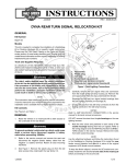
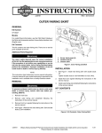
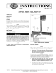
-J05945
REV. 2014-10-15
FRONT DIRECTIONAL LIGHT RELOCATION KIT - XL1200X
3.
See Figure 1. Remove connector housing (F) from turn
signal assembly harness. Note terminal (G) locations. See
the service manual.
4.
Remove right front turn signal assembly from original
equipment (OE) location. See the service manual. Retain
all mounting hardware. Note turn signal harness routing.
For model fitment information, see the P&A Retail Catalog or
the Parts and Accessories section of www.harley-davidson.com
(English only).
5.
Remove nut (E), washer (D), and turn signal assembly (A)
from OE turn signal mount.
Installation Requirements
6.
Remove right pinch screw from the lower fork bracket.
7.
Install pinch screw from right side of lower fork bracket to
the upper pinch screw location. Tighten to 30-35 ft-lbs
(40.7-47.5 Nm). See the service manual.
8.
See Figure 1. Route the turn signal assembly terminals
(G) and wiring through the turn signal mount (1).
9.
Install turn signal assembly to turn signal mount. Secure
with lockwasher (D) and nut (E). Tighten to 12-16 ft-lbs
(16.3-21.7 Nm).
GENERAL
Kit Number
67800452, 67800489
Models
The rider's safety depends upon the correct installation
of this kit. Use the appropriate service manual procedures.
If the procedure is not within your capabilities or you do
not have the correct tools, have a Harley-Davidson dealer
perform the installation. Improper installation of this kit
could result in death or serious injury. (00333a)
NOTE
This instruction sheet references service manual information.
A service manual for your model motorcycle is available from
a Harley-Davidson Dealer.
Kit Contents
See Figure 1 and Table 1.
INSTALL
10. Install turn signal mount assembly to the lower fork
bracket. Secure with previously removed upper pinch
screw. Tighten pinch screw to 30-35 ft-lbs (40.7-47.5 Nm).
11. Repeat steps 4 through 11 for the left side front turn signal.
12. Route the turn signal wiring for each turn signal to the
main harness as previously noted. Secure wiring with
cable straps (2).
13. Install turn signal wire terminals (G) into the previously
removed connector housing as noted. See the service
manual.
To prevent accidental vehicle start-up, which could cause
death or serious injury, remove main fuse before proceeding. (00251b)
1.
Remove main fuse. See the service manual.
2.
Disconnect front turn signals from main harness. See the
service manual. Note wire routing and cable strap locations.
14. Connect front turn signal connectors to main harness. See
the service manual.
15. Install the main fuse. See the service manual.
Be sure that all lights and switches operate properly before
operating motorcycle. Low visibility of rider can result in
death or serious injury. (00316a)
16. Verify that turn signals operate properly.
-J05945
Many Harley-Davidson® Parts & Accessories are made of plastics and metals which can be recycled.
Please dispose of materials responsibly.
1 of 2
SERVICE PARTS
is08485
2
1
F
G
C
B
E
D
A
1
Figure 1. Service Parts: Front Turn Signal Relocation Kit - XL1200X
Table 1. Service Parts Table
Item
Description (Quantity)
Part Number
1
Turn signal mount (2)
Not Sold Separately
2
Cable strap (4)
10006
Items mentioned in text, but not included in kit:
A
Front turn signal assembly
B
Screw
C
Flat washer
D
Lockwasher
E
Nut
F
Connector housing
G
Terminal
-J05945
2 of 2