1
Enhanced Programmable
Logic Controller Gateway
Control Functions
EP09-400
Implementation
EPLC Gateway
Enhanced Programmable
Logic Controller Gateway
Control Functions
EP09-400
Release 430
9/97
Copyright, Trademarks, and Notices
© Copyright 1992 - 1997 by Honeywell Inc.
Revision 02 – September 20, 1997
While this information is presented in good faith and believed to be accurate,
Honeywell disclaims the implied warranties of merchantability and fitness for a
particular purpose and makes no express warranties except as may be stated in its
written agreement with and for its customer.
In no event is Honeywell liable to anyone for any indirect, special or consequential
damages. The information and specifications in this document are subject to
change without notice.
Honeywell, TotalPlant, and TDC 3000 are U.S. registered trademarks of Honeywell
Inc.
Other brand or product names are trademarks of their respective owners.
About This Publication
This is a reference manual for process engineers, control system engineers, and application
engineers who design and implement data acquisition and control strategies to be
accomplished through a TDC 3000 System with a Local Control Network. This
publication defines the data acquisition and control functions that reside in Programmable
Logic Controller Gateways and the Programmable Logic Controllers connected to the
EPLCG.
This publication is a new member of a set of publications that define control system
functions. The other members of the set are: System Control Functions, Process Manager
Control Functions and Algorithms, Hiway Gateway Control Functions, and Application
Module Control Functions.
For the most effective use of this manual, you should be familiar with the concepts and
terminology introduced in the System Control Functions manual.
This publication supports TDC 3000 software Release 430 and later.
EPLC Gateway Control Functions
9/97
EPLC Gateway Control Functions
9/97
Table of Contents
1
REFERENCES
1.1
2
EPLCG DATA ACQUISITION AND CONTROL FUNCTIONS
2.1
2.2
2.3
2.3.1
2.3.2
2.3.3
2.3.4
2.3.5
2.3.6
2.3.7
2.3.8
2.3.9
2.4
2.4.1
2.5
2.5.1
2.5.2
2.6
2.6.1
2.6.2
2.6.3
2.6.4
2.7
2.7.1
2.7.2
2.7.3
2.7.4
2.7.5
2.7.6
2.7.7
2.8
2.8.1
2.8.2
3
References
EPLCG Scope
Hiway States
DHP Status
Run State
Run-SF
Run-PF
Idle-SF, Idle-PF
Fail-COM
Fail-HDW
Reset
Uncertain
DHP Control States
EPLCG Backup
EPLCG Failover Scenario
EPLCG Parameter Configuration and Error Codes
Avoiding Errors
Errors on Input and Output Requests to PLCs
EPLCG Parameter Configuration
Relating EPLCG Boxes and Slots to PLCs and PLC Addresses
Reserved Entities
Parameter Configuration
Quick Reference to Modbus Protocol
EPLCG Data Point Capacity
Total EPLCG Point Capacity
Composite Points in One Box
Fifty Points with Critical Alarm Status
Momentary ("Doorbell") Digital Points
Analog Input Points
Points with Event-Initiated Processing
Contact-Cutout Secondary Points
Special EPLCG Functions
Functions Related to Emulated DHPs
Special Functions Related to Process-Connected Subsystems
DETAILED DATA POINT DESCRIPTIONS
3.1
3.1.1
3.1.2
3.1.3
3.1.4
3.1.5
3.1.6
3.1.7
3.1.8
3.1.9
EPLCG Analog I/O Data Points
Analog I/O Point Types
Functional Structure of Analog I/O Points
Processing Order for Analog I/O Points
First Level Processing of Analog I/O Points
Second Level of Analog I/O Processing
PV Source Selection for Analog I/O Points
PV Range, PV Clamping Options, and PV Value Status
Analog Output Data Point Modes
Point Alarming for Analog Input Points
EPLC Gateway Control Functions
i
9/97
Table of Contents
3.1.10
Alarm Limits (PVLOTP, PVHITP, DEVLOTP, DEVHITP)
3.1.11
Event-Initiated Processing for Analog Input Points
3.1.12
Analog I/O Point Addressing
3.2
EPLCG Digital I/O Data Points
3.2.1
Digital Input Points
3.2.2
EPLCG Digital Output Data Points
3.2.3
EPLCG Digital I/O Composite Data Points
3.2.4
Digital Alarms
3.3
EPLCG Counter Data Points
3.3.1
Functional Structure, EPLCG Counter Point
3.3.2
Counter Functions
3.3.3
EPLCG Counter Parameters
3.3.4
EPLCG Counter Processing
3.4
EPLCG Hiway and Box/Slot Data Points
3.4.1
Hiway Point Parameters
3.4.2
Box/Slot Data Point Processing
3.4.3
Box/Slot Data Point Parameters
3.4.4
Box/Slot Point Names
EPLC Gateway Control Functions
ii
9/97
1
REFERENCES
Section 1
This section provides references to other publications that are useful or necessary in
implementing control system functions.
1.1 REFERENCES
This manual describes the data acquisition and control functions that reside in EPLCGs and
the logical boxes that are in the EPLCGs. There are two companion publications:
• System Control Functions, in the Implementation/Startup & Reconfiguration - 2
binder—describes data acquisition and control functions that are independent of the
module or gateway they reside in.
• Application Module Control Functions, in the Implementation/Application Module - 1
binder—describes data acquisition and control functions in Application Modules.
You should be familiar with the content of System Control Functions before using this
publication or other control function publications.
Other topics related to data acquisition and control functions are covered in these
publications:
• Preparation of Control Language Programs—First refer to the Control
Language/Application Module Overview, in the Implementation/Application Module - 2
binder. Then refer to the Control Language/Application Module Reference Manual, in
the same binder. These manuals cover both continuous control programs that run in
AMs and CL/MC programs that run in MCs.
• Parameters—For details on all of the data point parameters, including value types,
default values, and access levels (keys), refer to the following publications:
EPLC Gateway Parameter Reference Dictionary, in the Implementation/EPLC
Gateway binder.
Application Module Parameter Reference Dictionary, in the
Implementation/Application Module - 1 binder.
EPLC Gateway Control Functions
1-1
9/97
EPLC Gateway Control Functions
1-2
9/97
2
EPLCG DATA ACQUISITION AND CONTROL FUNCTIONS
Section 2
This section defines the data acquisition and control functions, other than data point functions,
that are accomplished in a Enhanced Programmable Logic Controller Gateway (EPLCG). The data
point functions are defined in Section 3.
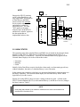
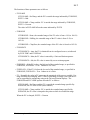
The Enhanced Programmable Logic Controller Gateway (EPLCG) is an LCN node that
provides a direct interface to any of several Programmable Logic Controllers (PLCs)
available from various manufacturers. A single EPLCG can be connected through its two
ports to up to 16 PLCs. The EPLCG database is organized into eight logical boxes as
viewed by the LCN and the configuration software. The EPLCG may be provided as a
redundant node pair, consisting of a primary EPLCG backed up by its redundant partner.
Should the primary EPLCG fail, its partner takes over all of the failed node’s functions,
using the current database. The EPLCG’s redundant communications configuration can
also provide I/O network redundancy.
An EPLCG can handle up to 3,000 LCN data points of these seven types:
•
•
•
•
Analog Input
Analog Output
Analog Composite
Counter (timer)
•
•
•
Digital Input
Digital Output
Digital Composite
Some LCN data points (composite points) use two or more memory locations in the
EPLCG; therefore, when these types are used, the capacity is limited to 240 point database
“slots.”
Functionally, the EPLCG is similar to the Hiway Gateway (HG), and it operates on the
HG software, as is, with no modifications. The EPLCG operates as if it were a Data
Hiway with up to eight Data Hiway Ports (DHPs). All operating and configuration
displays for EPLCGs are HG displays with no modifications, including the HG and DHP
terminology.
DHPs are Data Hiway boxes (each an independent hardware module) that interface with
PLCs. The EPLCG offers better performance because data is transferred through the
EPLCG more quickly than over a Data Hiway and through DHPs.
2.1 EPLCG SCOPE
The EPLCG was designed primarily for data acquisition and supervisory-level control. In
supervisory control schemes, the EPLCG supports limited writes of set-point type data,
while the PLC performs high-speed control sequencing.
A typical EPLCG/PLC control application can be depicted with a ten-motor conveyor belt.
For proper operation, the startup/shutdown sequence of the individual motors must be
precisely controlled. To start or stop the belt, an operator performs a single write from the
EPLCG to the PLC. The PLC would then be responsible for performing the detailed
operation that results in the desired change.
EPLC Gateway Control Functions
2-1
9/97
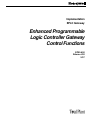
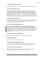
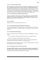
2.2
NOTE
US
LCN
PRIMARY EPLCG
HG
DHP
PLC
DHP
PLC
BOXES AND DATA HIWAY ARE EMULATED
BOXES
DATA HIWAY
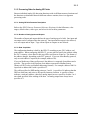
Because the EPLCG emulates
an HG with a Data Hiway and
up to eight DHPs, all references
to Data Hiways and DHPs
(boxes) refer to the emulated
devices (and to emulated slots
and subslots), and not to
physical devices. The term
“slot” applies to the point
memory space in the EPLCG,
and the term “subslot” applies to
the data points that are
implemented in these slots.
1
BACKUP
EPLCG
2
PLCs
3
4
5
PLCs
6
7
8
PORTS 1 & 2
Short Haul Modems
or Communication
Interfaces
11567
2.2 HIWAY STATES
The operating states of the emulated hiway and DHPs are presented on the Network Status
display for each EPLCG. While there is no Data Hiway connected to the EPLCG, it
behaves as if there is a Data Hiway. Therefore, the emulated Data Hiway appears on the
Network Status Display to be in one of these three states:
• Uncertain
• Running
• Failed
Initially, before Data Hiway security checks have been made, or when starting up a hiway
without a database, the status of a emulated hiway is set to Uncertain.
In the running state, interfaces to the hiway are operational and normal communication over
the hiway is possible. The Network Status display for each Data Hiway shows which
logical hiway (A or B) is active.
Restart of a backup EPLCG does not cause a change in the hiway state. A failure in the
EPLCG (both redundant EPLCGs) or the emulated hiway (A and B out of service) changes
the hiway status to "failed."
NOTE
Hiway state and indication is not related to conditions on the serial communication link
between EPLCG and the PLCs.
EPLC Gateway Control Functions
2-2
9/97
2.3
2.3 DHP STATUS
The state of an emulated DHP is determined by the EPLCG, but only when the hiway is in
the running state. If the hiway has failed, an access error indication is returned when an
operator or LCN module tries to read from, or write to, an emulated DHP. The operational
states for process-connected boxes are:
•Run *
•Run-SF (soft failure)
•Run-PF (partial failure)
•Fail-COM (Hiway Status diagnostic failure)
•Fail-HDW (hardware)
•Reset
•Uncertain
* A DHP enters the Run state when an operator at a Universal Station uses the Network
Status display and box commands to tell it to do so.
2.3.1 Run State
The emulated DHP is fully operational; the hiway security check has qualified the box.
Run state is indicated by OK status on the Hiway status display.
This state can be selected by the operator from the Reset state by using the ENABLE
processing box command, if the box is operational and qualified.
2.3.2 Run-SF†
The emulated DHP is in Run and a soft failure has been detected.
2.3.3 Run-PF†
A partial failure has been detected in the emulated DHP. Some points are affected (their
state is failed); unaffected slots operate normally.
2.3.4 Idle-SF, Idle-PF†
The emulated DHP is in the idle state and a soft failure (-SF) or a partial failure (-PF) has
been detected.
2.3.5 Fail-COM
The emulated DHP failed the hiway security check, or an addressing error was detected.
All communication to the DHP, except for hiway security tests, are inhibited. The
functional status is set to Basic Control.
† Because there are no physical DHPs, this will not normally occur.
EPLC Gateway Control Functions
2-3
9/97
2.3.6
2.3.6 Fail-HDW†
The EPLCG has determined that the emulated DHP has failed; the functional state is set to
Basic Control (read and write access from AMs and CGs is inhibited). This state can be set
by only the EPLCG.
Box HDW Failure Definition—A box failure is the inability of the EPLCG to communicate
with a specific DHP. With a real Hiway, this could be a result of communication errors
other than those detected by the hiway security check, including no response, but is not
likely to occur in a EPLCG. In such a situation, the EPLCG changes the state of the DHP
to "failed." In the absence of such a condition, the EPLCG sets the state of the DHP to the
one that is determined from the box status words.
2.3.7 Reset
The emulated DHP itself detected a fatal error and reset itself; the functional status is set to
"basic control" and read or write access from an AM or CG is inhibited. One of the DHPs
can also be commanded reset by using the START Box Command function.
2.3.8 Uncertain
The emulated DHP has not yet been qualified by the hiway security check and
communication with it is inhibited. The functional status of the DHP is set to "out-ofservice for control."
2.3.9 DHP Control States
The control states are Basic, Read, Full, and Test. (If you need more information, refer to
subsection 3.3.8 in System Control Functions.) The emulated DHP’s states can change
from one state to any other; however, changes from Fail-COM, -HDW, and Uncertain
force the functional status to Basic Control.
† Because there are no physical DHPs, this will not normally occur.
EPLC Gateway Control Functions
2-4
9/97
2.4
2.4 EPLCG BACKUP
2.4.1 EPLCG Failover Scenario
Switching from an active EPLCG to the backup is accomplished with as little disruption to
control and data acquisition as possible. These two factors are very important in failover
processing:
• Time-out handling
• Time to restore communication on the emulated Data Hiway.
It takes the backup 1 second to detect a failure in the primary EPLCG. When it does detect
a failure, it attempts to directly communicate with the primary EPLCG. If this
communication isn't reestablished within 2 seconds, the backup requests the error-handling
subsystem to determine whether to replace the active EPLCG. While waiting for this
swap, the backup proceeds with the following two functions:
1. Hiway security checking is started by the backup, and the scanning of the points with
the 50 most critical (emergency priority) alarms begins.
2. The time-out gates in the boxes are updated so that control shedding doesn't occur.
When the system error handler determines that the formerly active EPLCG has failed,
failover processing continues. The total time to complete the failover is about five seconds.
As failover processing continues, the following takes place:
3. The backup (secondary) becomes active (primary).
4. All functions that receive event messages are notified that failover has occurred and
the distribution of the highest-priority alarms begins.
5. Requests for data from the EPLCG are processed according to these priorities:
• Control-function requests
• Operator-initiated requests
• Display updates
6. Alarms other than the 50 critical alarms are processed.
7. Remaining requests for data from the EPLCG are processed.
8. All remaining functions resume, including checkpointing of EPLCG data, history
collection, and trending.
EPLC Gateway Control Functions
2-5
9/97
2.5
2.5 EPLCG PARAMETER CONFIGURATION AND ERROR CODES
After you have used the Data Entity Builder to build and load EPLCG points, you may
encounter error codes for one or more emulated DHPs on the Operator Personality’s
Network Status display for the EPLCG’s hiway. These errors are likely to be caused by
configuration errors, such as incorrect PLC addresses.
2.5.1 Avoiding Errors
If you incorrectly define an EPLCG data point, the PLC may report an error in its
response, resulting in PCCONFxy = BAD for the DHP point and failure of the slot to
which it is loaded. The DHP may also report a status change error, which can be decoded
with information from the EPLCG Planning, Installation, and Service manual. These
errors are sometimes difficult to isolate, so use caution when changing DHP points or
loading for the first time. This occurs because the point number is referencing a PLC point
address which is not configured. These errors are sometimes difficult to isolate; however,
once you have identified the troubled slot, you can disable the emulated DHP. This allows
the Detail Displays access to the PLC database, and you can then search through the
tagnames associated with the error.
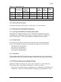
NOTE
When deleting a DHP point with the DELETE ENTITY function of the Data Entity Builder (DEB),
be sure to first set to zero (0) the PCADDRxy and SPECIFxy (Modbus), or PCBITxy (AllenBradley digital) parameters for the DHP point. The DELETE ENTITY function does NOT delete
point data from the emulated DHP box memory, and the point will continue to be read from the
PLC as long as the PCADDRxy and SPECIFxy or PCBITxy parameters are non-zero. This is
commonly referred to as a “ghost point.”
To avoid these kinds of errors, it is a good idea to enter all PLC points and their
corresponding TotalPlant Solution (TPS) system tagnames into a database program on a
personal computer. The data can then be sorted in any way you need, and you’ll be able to
track which PLC points correspond to which tagnames. Remember to update the database
anytime you make changes to the EPLCG configuration.
2.5.2 Errors on Input and Output Requests to PLCs
The EPLCG attempts to read all configured PLC data with every scan, but an error detected
during a normal scan request is not shown on the Operator Personality’s Network Status
Display until retries also fail. The failed request will be retried two more times. If the error
was only transient, the points and slots associated with that request will not indicate failure.
If the error persists, the slots will fail and thereafter the PLC device is checked once each
scan to allow error recovery.
When you attempt to change the state/value of a PLC point, you make an output request.
Output requests have three sources:
• Operator changes
• Changes from an AM
• PLC keep-alive addresses
EPLC Gateway Control Functions
2-6
9/97
2.6
Because such requests can occur anytime, the system also performs a retry, if appropriate.
The number of retries allowed is specific to the communications protocol in use. ModBus
requests are retried twice, while Allen-Bradley requests are retried three times (as
recommended by the vendors).
Please note that a retry is performed anytime there is a transient type error condition.
Under certain conditions, such as configuration errors, retries do not alter the results and
are, therefore, suppressed.
2.6 EPLCG PARAMETER CONFIGURATION
2.6.1 Relating EPLCG Boxes and Slots to PLCs and PLC Addresses
The PLCG must be configured in this order to work properly:
1. Hiway Point
2. Box Points (HGbox[es], then DHP boxes)
3. Data Points
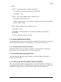
Each EPLCG has up to eight emulated boxes (numbered 8-15) each of which contains up
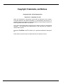
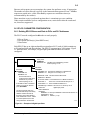
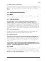
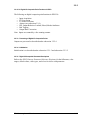
to 30 emulated slots and their subslots. The EPLCG supports up to 3,000 points. Figure
2-1 illustrates how, for example, a digital input point named PDI001A would be
configured:
Hiway Point
$HIWAY02
HWYNUM = 02
EPLCG
This EPLCG is identified by processnetwork (hiway) no. 02 .
8 9 10 11 12 13 14 15
Box Point
$HY02B02
HWYNUM = 02
BOXNUM = 02
The EPLCG must be
configured as an HG at box
address 02 on processnetwork (hiway) no. 02.
If this EPLCG has a redundant
partner, it too has an HG box
point, $HY02B03.
Box Point
$HY02B15
HWYNUM = 02
BOXNUM = 15
As with a physical hiway, the
EPLCG itself always uses hiway
address numbers 02 and 03;
therefore, hiway state displays
show addresses 2 and 3. If there
is no backup EPLCG, the odd
hiway address is still reserved.
This EPLCG subdivision is identified as
being box 15 on hiway no. 02.
BOXTYPE = DHP This box behaves like a DHP.
BOXPROT = Modicon
PC1TYPE = M584 Connected device is a Modicon 584 PLC.
PC1PORT = 1
The PLC is connected to EPLCG port no. 1.
PC1PORTA = 17 The PLC Modbus address is 17.
PIUCRDTY(2) = DIGITIN Slot 2 of box 15 serves up to 16
digital input points.
Data Point
Name=PDI0001A
PDI0001A
BOXNUM = 15 This input database is stored in EPLCG box 15,
SLOTNUM = 2 slot 2,
INPTSSLT = 1 subslot 1 (1-16).
11748-A
Figure 2-1 — Example of a Digital Input Point
EPLC Gateway Control Functions
2-7
9/97
2.6.3
2.6.2 Reserved Entities
When configuring a PLC for the network, you must be sure to configure all required
reserved entities. There are up to 11 reserved entities (names for reserved entities begin
with $). These reserved entities are:
$HIWAYnn
Hiway Point; one per EPLCG or EPLCG redundant pair.
nn=network (hiway) number.
$HYnnBaa
(for EPLCG)
Box Point; one per EPLCG or each partner of a EPLCG
pair. nn=network (hiway) number and aa=box address number
(02, 03 for redundant EPLCG).
$HYnnBaa
(for emulated
Hiway DHP
Boxes)
Box Point; one per emulated DHP. nn=network
(hiway) number and aa=box address number (08-15).
NOTE
Digital Composite and Analog Composite points exist in an EPLCG, but are not structured the
same as corresponding Digital Composite and Analog Composite points in the PM/APM.
EPLC Gateway Control Functions
2-8
9/97
2.6.3
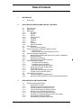
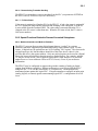
2.6.3 Parameter Configuration
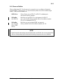
ENTITY / PARAMETER
DEVICE / SUBDIVISION
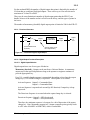
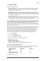
Figure 2-2 shows the structure of the EPLCG as it relates to the parameters in the reserved
entities and an example data point:
LCN
EPLCG
BOX
(up to 8
numbered
8-15)
SLOTS
(up to 30)
SUBSLOTS
Type
Digital Input
Digital Output
Digital Composite
Analog Input
Analog Output
Analog Composite
Counter
$HIWAYn (1)
$HYnnBnn (1)
$HYnnBnn(8)
HWYNUM
HWYHTD
HWYSWINT
HWYSWBAS
SOESYNCH
CDTEXT
NCMPTXT1
NCMPTXT2
HWYNUM
BOXNUM
BOXTYPE
BOXASSN
LOADDEST
EVENTPRC
HWYNUM
BOXNUM
BOXTYPE
BOXASSN
LODDEST
BOXSIZE
BOXPROT
BOXSTART
SCANTIME
PCnTYPE
PCnPORT
PCnPORTA
PCnALIVE
PCnALVBT
PCnALIVE
PCnALVBT
PCnALVSP(MODBUS)
PCnPORT
PCnPORTA
PCnTYPE
PNCRDTY
CHNGFLAG
EVENTPRC
BOXTOG1
BOXTOG2
TOSINTSL
EPLCGs
Max Points
16
8
4
6
4
2
8
DATA POINT
PNTBOXOT
ALFMT
PNTBOXTY
ALPRIOR
PNTPCTY
BOXNUM
PRIMOD
CALIBOFF
PTDESC
CCRANK
PTDISCL
EIPENB
PVALDB
EIPEVENT
PVCLAMP
EIPPCODE
PVDSPHI
EUDESC
PVDSPLO
HWYNUM
PVEUHI
INPTDIR
PVEULO
INPTSSLT
PVFORMAT
KEYWORD
PVHITP
LBOXCLR
PVLOTP
LOADDEST
PVRNGOP
MODE
PVSTS
MODEPERM
PVTV
MOOUTIND
RCASENB
NAME
RNGCODEn
NMODE
SLOTNUM
OUTIND
SPECIFI1
BOXOUTNUM
SPECIFO1
OUTSLTNM
SPECIFOR
OUTSSLT
STATE
OVERVAL
STATE1
PCADDR1
STATE2
PCADDRI2
UBOXCLR
PCADDRO1
UNIT
PCADDRO2
ZZTEXT
PIUCRDTY
PNTBOXIN
11681
Figure 2-2 — EPLCG Structure and Reserved Entities
EPLC Gateway Control Functions
2-9
9/97
2.6.4
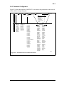
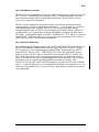
2.6.4 Quick Reference to Modbus Protocol
This subsection provides a key to Modbus protocol that may be needed for your application.
Modbus RTU Address Map for EPLCG
EPLCG
Point type
Modbus Memory
(1), (2)
Address
Digital Output
00001-09999
Digital Input
(5)
Analog Input
00001-09999
or
10001-19999
30001-39999
or
40001-49999
Modbus Function & Code:
Read from PLC
Write to PLC
Read Coil Status
01
Force Single Coil
05
Read Coil Status
01
or
Read Input Status
02
no write allowed
Read Input Registers
04
or
Read Holding Registers 03
no write allowed
Analog Output
40001-49999
Read Holding Registers 03
Preset Single Register 06
Counter
40001-49999
Read Holding Registers 03
Preset Single Register
06
(1)
(2)
(3)
(4)
(5)
Data format
Data Range
(3), (4)
bit/coil
0 (OFF) or
1 (ON)
bit/coil
0 (OFF) or
1 (ON)
Least 12
bits of
unsigned
16-bit
register.
Least 12
bits of
unsigned
16-bit
register.
16-bit
unsigned
integer
0-999 or
0-4095 or
0-9999
0-999 or
0-4095 or
0-9999
0-65,535
Modbus memory address is split into 2 parameters for DHP point configuration on LCN.
Most significant digit (10K position) is entered as parameter SPECIFxy, lower 4 digits are
parameter PCADDRxy (x = I or O; y = 1 or 2).
This is not the Modbus slave address of the PLC device, which is determined by PLC
configuration or switch setting, and entered in parameter PCxPORTA on LCN box/slot
config (entity $HYnnBaa), range 1-247.
Data range for analogs is set via parameter RNGCODEx, and the PLC must match this data
range to transmit or receive values on the communication link. Value is processed as
percent of range for conversion to Engineering Units. Range is not configurable for other
point types.
Counter value can be scaled by the AVCONV parameter. Typically, set AVCONV = 1.
Packed Digital Inputs (PLCG and EPLCG only): DI points may read data from registers
packed with discreet status. Use PCADDRIx = 4xxxx (SPECIFIx = 4, PCADDRIx =
0001-9999)
This uses Modbus function 03, Read Holding Register, with the same behavior as Analog
Input or Counter, except the bits are unpacked by EPLCG and used in bit order for subslot
order. That is:
PLC register bit 0 (LSB) ---->
DI subslot 01
PLC register bit 1 --------->
DI subslot 02
:
PLC register bit 15 (MSB) -----> DI subslot 16
Only 1 packed register can be used in a DI slot, but not all subslots in same slot must use
packed format. For example, you can configure subslots 1-5 to use 5 lowest bits of packed
register 40010, then use subslots 6-16 each with a unique 0xxxx or 1xxxx address value.
Unused bits of the packed register will be discarded. (Note (5) continued on next page.)
EPLC Gateway Control Functions
2-10
9/97
2.6.4
(Note (5) Continued)
When the BLOCK MOVE function is used in Modicon controllers, the first (lowest)
addressed discrete location will end up in the register MSB, bit 15, and highest discreet
address in the register LSB, bit 0. Other Modbus devices may not pack in reverse order.
In any case, the EPLCG unpacks bits in the order shown above.
Listed below are other notable points and features for Modbus devices:
•
•
Protocol is Modicon, model type 584 (384 and 484 are also supported).
Port is 1 to 4 for DHP, and 1 to 2 for EPLCG (LCN parameter PCxPORT).
•
Maximum number of registers requested per transaction:
DHP = 32 register values [analog or counter] (=64 bytes), or 64 coils [digitals]
(=4 bytes)
PLCG = 64 register values [analog or counter], or 64*16=1024 coils
[digitals]
•
Error Detection and Retry features on communication link:
(Retry information is based on current documentation, but is subject to change.)
Error description
Message Retried?
CRC-16 error
Yes
Message timeout
Yes
( timeout is 1.5 sec for [E]PLCG, 3.0 sec. for DHP)
Wrong PLC device replied
Yes - for output only
Reply message length incorrect
Yes - for output only
Reply length inconsistent with byte count
Yes - for output only
Modbus Exception Codes:
01
Illegal Function
No
02
Illegal Data Address
No
03
Illegal Data Value
No
04
Failure in PLC (slave) device
No
05
Acknowledge (ACK)
No
06
PLC (slave device) busy
Yes
07
Negative Acknowledge (NAK)
No
Exception codes 01, 02, 03, 04, 05, and 07 will cause the DHP/PLCG point to go
to a BAD state and fail the entire slot to which it’s assigned. This does not cause
failure of the associated device in the DHP box configuration, so points in other
slots will function.
Unless retry is successful, all other faults will cause failure of the associated device
in the DHP box configuration and all associated points and slots, so point data will
not be updated until the fault is cleared. A failure indication will be reported on the
Honeywell system.
•
11-bit character format: 1 start + 8 data + parity + 1 stop = 11 bits.
•
Error checking: Parity (per character) + CRC-16 (per message packet).
•
End-of-message gap is defined as 3.5 character times or more, per Modbus
specification.
EPLC Gateway Control Functions
2-11
9/97
2.7
2.7 EPLCG DATA POINT CAPACITY
The following are configuration limits and restrictions that apply to EPLCG data points.
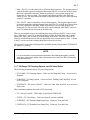
2.7.1 Total EPLCG Point Capacity
If you refer to the “MaxPoints” column under “Subslots” in the chart above, you can
calculate that if all points were digital inputs, you could have as many as 16 digital
inputs X 30 slots X 8 DHPs = 3,840 points in a EPLCG; however, the maximum number
of data points that can be built for a EPLCG (or EPLCG pair) is 3,000. Each emulated
DHP has 30 slots and each slot has 4, 6, 8, or 16 subslots, depending on the point type, as
indicated on the chart above. Composite points consume more than one EPLCG memory
location; therefore, the total point capacity is the lesser of 3,000 points or 240 slots of data.
2.7.2 Composite Points in One Box
Composite Analog I/O and Composite Digital I/O points must be configured for the same
EPLCG and the same DHP (box). The input and the output cannot be in different boxes.
For more information, see subsections 3.1 and 3.2.
2.7.3 Fifty Points with Critical Alarm Status
Up to 50 data points can be configured for critical alarms (ALPRIOR for such points is
configured as Emergncy). These points are specially checked on EPLCG startup or
failover to see if an alarm has been detected during the failover operation. During failover,
alarms that have a lower status than critical are not distributed. In normal operation, points
with ALPRIOR = Emergncy are scanned by the EPLCG at 1/2-second intervals for alarm
condition. These points are updated from PLC memory at the same rate as all other
EPLCG points.
2.7.4 Momentary ("Doorbell") Digital Points
EPLCGs can have up to 500 momentary or "doorbell" digital output points.
2.7.5 Analog Input Points
EPLCGs can have up to 1,440 analog input points.
2.7.6 Points with Event-Initiated Processing
EPLCGs can have up to 600 configured for event-initiated processing (EIP) points. (If
you need more information, refer to subsection 4.2 in System Control Functions.)
2.7.7 Contact-Cutout Secondary Points
Up to 500 points can be configured as secondary cutout points. (If you need more
information, refer to subsection 4.3.1.7 in System Control Functions.)
EPLC Gateway Control Functions
2-12
9/97
2.8
2.8 SPECIAL EPLCG FUNCTIONS
This subsection defines specific control functions that are performed by the EPLCGs. The
purpose of the section is to clarify that though these functions may be covered elsewhere in
the System, HG, and AM Control Functions publications, they are accomplished by the
EPLCG.
2.8.1 Functions Related to Emulated DHPs
2.8.1.1 Startups
The EPLCG handles the necessary initialization for all emulated DHPs, with the exception
of Clearance Hiway Security Errors (an address error on the Hiway Status Display). This
error must be cleared by the operator.
2.8.1.2 Control Time-Out Function
For emulated DHPs, the EPLCG provides a time-out function similar to that of the
Extended Controller. The box-level time-out gates are automatically updated by the
EPLCG as long as the box is in the "full control" state, secondary points in the box are in
CAS mode, and their primary points in an AM continue to supply new SP or OP values to
their secondary points. In addition, each slot can be assigned (parameter TOGINTSL) to
one of two time intervals configured for its box (BOXTOGn). These intervals are the timeout periods for the slot. A write to the SP or OP parameter of a point in a slot, resets the
timer.
2.8.1.3 General Parameter Access
The EPLCG provides access to all accessible parameters in the emulated DHPs. The
EPLCG returns an error indication if an invalid access request is made.
2.8.1.4 PV Source Selection
The EPLCG provides selection of PV sources for all analog input and digital input data
points. While the PV source is manual or substituted, mode changes are inhibited. Access
to the PV Auto value is available when the PV source is manual or substituted. Values of
PV MAN and PV SUB are limited to the PV range. While the PV source is manual or
substituted, PV alarms are inhibited. A bump in the PV can occur when changing from
SUB to AUTO.
When PVSOURCE equals MAN or SUB, the manually entered or substituted PV value is
held in the EPLCG, while the PV in the emulated DHP (visible at the LCN as PVAUTO) is
unaffected. Alarm checking continues on the PV in the box.
2.8.1.5 Clamping
If PV clamping is configured for a data point (PVCLAMP = Clmp), clamping is handled by
the EPLCG. For the full-range clamp option, the PV is clamped at -2.9% of the range
when the variable goes below that value, and it is clamped at 102.9% if the variable goes
above that value. A zero-clamp option is also available, where the PV is clamped at 0% of
the range if the variable goes below that value.
EPLC Gateway Control Functions
2-13
9/97
2.8.1
2.8.1.6 Reverse-Acting Transmitter Handling
The EPLCG accommodates reverse-acting data from the PLC (see parameter OUTIND in
the EPLC Gateway Parameter Reference Dictionary).
2.8.1.7 PV Value Status
Value status is assigned to all analog PVs by the EPLCG. A bad value status is assigned if
the PV is outside the range and the extension and clamping is not configured, or if the PV
is not available from the emulated DHP. The value status is uncertain when the PV is
clamped or the PV source is other than auto. When the PV status is bad, the PV value is
NaN (not a number).
2.8.2 Special Functions Related to Process-Connected Subsystems
2.8.2.1 Modicon Controllers and Modicon Emulators
The EPLCG can scan discrete status (digital inputs) that are “packed” in a register.
Modicon controllers support this operation and possibly some emulator types. For this
feature, 16 digitals may be packed into one 16 bit “holding” PLC register. The slot must be
a digital input type slot, but the address should be of the form 4xxxx, where 4 is the
specifier and xxxx is the register address. Only one packed register can be used in a Digital
Input slot, but not all subslots in that slot must use packed format. For example, subslots
1-5 may be use the lowest 5 bits of packed register 40010, then subslots 6-16 used with
unique 0xxxx or 1xxxx addresses. Refer to EPLC Gateway Forms if you need more
information.
The EPLCG may be configured to suppress the periodic scanning of analog or digital
outputs from Modicon controllers. During configuration, create a logical Modbus PLC
using Port No. = 3 or 4 on the actual Port 1 or 2, respectively. Then configure any
nonscanned points against this logical PLC. If anyone attempts to configure an input point
(analog, digital, or counter) against a nonscanning logical PLC, a configuration error will
occur.
EPLC Gateway Control Functions
2-14
9/97
2.8.2
2.8.2.2 Allen-Bradley Controllers
The EPLCG may be configured to accept only binary data (registers or counters) from A-B
PLC-3 or PLC-5 controllers by selecting type “APLC” during configuration. Any other
selection means the data will be accepted only in BCD form. Refer to EPLC Gateway
Forms if you need more information.
The PLC may be configured to accept data sent by A-B PLCs by unsolicited messages
(scan suppression). During configuration, use Port No. = 3 or 4 to mean Port 1 or Port 2
with scanning suppressed. Actually, the EPLCG will accept unsolicited messages
(exception reports) from A-B PLCs even if scanning, but if both the EPLCG and PLC is
configured for it, scan suppression can increase throughput. Standard A-B Data Hiway
rules apply. Configuration applies to each PLC definition (PC1, PC2, and so on.) for each
emulated DHP. Definitions may mix access types from the same physical PLC. Refer to
EPLC Gateway Forms if you need more information.
2.8.2.3 Keep-Alive Addressing
By configuring the $HYnnBaa parameters PCxALIVE and PCxALVBT (Allen-Bradley) or
PCxALVSP (Modbus or Honeywell) to non-zero values, the EPLCG writes a 1 to that
PLC location every 10 seconds through its emulated DHP. By doing this, the EPLCG
notifies the PLC that it is “alive.” If the EPLCG fails, it does not write the Keep-Alive
address, a timer in the PLC expires, and the PLC knows that the EPLCG is down. The
PLC can then take action, such as suspending batch operation, or sounding an external
alarm. The action the PLC takes is programmed in the relay ladder logic. The 10-second
Keep-Alive interval is fixed in the emulated DHP and cannot be changed. If the
PCxALIVE, PCxALVBT, and PCxALVSP parameters are set to zero (0) or left at default
NaN (----) value, the Keep Alive write is disabled for that DHP. See subsection 3.3.2.2 in
Enhanced Programmable Logic Controller Gateway Implementation Guidelines for “KeepAlive addressing.”
EPLC Gateway Control Functions
2-15
9/97
EPLC Gateway Control Functions
2-16
9/97
3
DETAILED DATA POINT DESCRIPTIONS
Section 3
This section provides a definition of the functions of the seven types of EPLCG data points: digital
input points, digital output points, digital composite points, analog input points, analog output
points, and analog composite points.
3.1 EPLCG ANALOG I/O DATA POINTS
Analog I/O data points represent analog inputs from the PLC and analog outputs to the
PLC. A composite analog I/O point provides one input and one output in the same data
point.
3.1.1 Analog I/O Point Types
There are three types of analog I/O data points:
• Analog Input—one input from a PLC.
• Analog Output—one output to a PLC.
• Analog I/O Composite—one input and one output with the same tag name. The input
slot (and subslot) and the output slot (and subslot) must be in the same emulated DHP.
3.1.2 Functional Structure of Analog I/O Points
• Analog input points have one input from a PLC and produce a PV with point status and
PV status.
• Analog output points have one output (OP) with related status and mode parameters.
• Analog I/O composite points combine one analog input and one analog output in one data
point with one tag name. They are intended to support displays and applications that use
an output with position feedback. They have an output value with its status and an input
PV with its status.
CAUTION
EPLCG users should bear in mind that inputs to, and outputs from, the EPLCG can be
affected by the ladder logic in the PLCs. When interpreting the process information on
Universal Station displays, operators, supervisors, and engineers must be aware of the effect
of ladder logic on the process inputs and outputs. For example an operator could command a
state change for a digital output, but the ladder logic might prevent that state change from
reaching the process equipment. For this reason, normal operation of the EPLCG is to scan
all output values from the PLC, as well as input values to provide value tracking.
EPLC Gateway Control Functions
3-1
9/97
3.1.3
3.1.3 Processing Order for Analog I/O Points
Because individual analog I/O data point functions reside in different memory locations and
the functions are distributed between different software routines, there is no apparent
processing order.
3.1.3.1 Analog I/O Point Parameter Descriptions
Refer to the EPLC Gateway Parameter Reference Dictionary for the full names, value
ranges, default values, value types, and access levels for these parameters.
3.1.3.2 Number of Analog Inputs and Outputs
The number of inputs and outputs defines the type of analog tag to be built. One input and
one output can be configured into the same tag. One input and no output is also allowed,
as is one output and no input. Tags with no inputs or outputs are not allowed.
3.1.3.3 Data Acquisition
The configuration database is built by the EPLCG according to port, PLC address, and
point address. When configuring the EPLCG, you are asked to specify the address within
the PLC’s memory, where data for this tag will be read from or written to. The format of
the address changes, depending on the PLC protocol. If you use Allen-Bradley protocol,
only an octal address is required (for example, address 010).
If you use Modicon or Honeywell protocol, the address is composed of an address and a
specifier. The specifier is the first part of an address expressed in Modbus format
(Honeywell PLCs also use Modbus addressing formats). For example, address 30001 is
expressed as address 0001 with a specifier of 3.
The valid specifiers for DHP analog points are 3 and 4. A specifier of 4 indicates that the
DHP can read from, and write to, the specified memory location. A specifier of three
indicates a read-only address; therefore, analog inputs can use a specifier of either 3 or 4
since both specifiers allow reading of the data. An analog output must always have a
specifier of 4.
EPLC Gateway Control Functions
3-2
9/97
3.1.4
3.1.4 First Level Processing of Analog I/O Points
3.1.4.1 PLC Range Codes
The PLC Range Code tells the emulated DHP how an analog input or output value is stored
in the PLC device. The emulated DHP then uses this information to convert the value to
the format that the TDC System uses, which is called B12E. The table below shows where
each Range Code is used.
Table 3-1 — Range Code and Where Used
Code
Range
Comments (See Note)
0
0-999
PLC, PLC2 family
1
0-4095
Used with Modicon PLCs, devices that
emulate Modicon, and Honeywell 620 Logic
Controller System.
2
0-9999
Used with Allen-Bradley PLCs, or any other
PLC that stores its values as numbers in this
range; PLC-3,5 families.
3-7
0-9999
Default to Range Code 2
Note: The Range Codes are typically used for the indicated PLCs, but any PLC device may use
any of the three codes, and that range in the PLC must match the RNGCODEX selection in the
DHP point.
B12E is a format that the TDC System uses to store its analog values. The acronym B12E
means the following:
B = Binary Number
12 = 12 integer bits (which implies three fractional bits and one sign bit)
E = Excess 247 (which means that 0% of engineering unit range is 247A/D counts
instead of zero).
The data read by the PLC gets into the emulated DHP in the following way. The PLC
device reads an input from some process-connected device, such as a transmitter. It then
stores the value in either raw A/D counts, or in BCD (as in the case of Allen-Bradley PLC2s). The emulated DHP then converts the data from the PLC’s data storage format to the
B12E format and it is used by the TDC 3000 System.
Once the value is stored as a B12E number, it can be converted to engineering units. No
matter what the data format or the engineering units used, the value can always be
expressed in percentage of engineering unit range, as shown in the following chart:
The equation used to determine the values of the B12E number is:
B12E = 3600 (PLC value/Range) + 247
EPLC Gateway Control Functions
3-3
9/97
3.1.4
Table 3-2 — Range Code Usage
From Xmtr
BCD in PLC
Raw A/D
Counts
in
(RNGCODE=0)
PLC
RNGCODE =2
B12E In
TDC
System
Eng Units
(See
Note)
% of EU
Range
(RNGCODE=1)
20 mA
999 BCD
4095 Counts
9999 Counts
3847
1000
100%
12 mA
500 BCD
2046 Counts
5000 Counts
2047
500
50%
4 mA
0 BCD
0 Counts
0 Counts
247
0
0%
Note: These values are user defined. Could be 0 - 1000, 0 - 500, -500 - 500, and so on.
3.1.4.2 Alarm Limits and Processing
For further information on this subject, see subsection 3.1.8 in this manual.
3.1.5 Second Level of Analog I/O Processing
3.1.5.1 PV Range Low (PVEULO) and PV Range High (PVEUHI)
During EPLCG configuration, these values are the number of engineering units that
correspond to 0% of range and 100% of range. In the above chart, 0% =0 degrees F;
100%=1,000 degrees F. These values should be configured before alarm limits.
3.1.5.2 Decimal Format
Decimal Format specifies the number of decimal places in the value displayed on the
screen. The example below shows how the analog value appears for each selection.
D0=XXXX. (no decimal places)
D1=XXX.X (1 decimal place)
D2=XX.XX (2 decimal places)
D3=X.XXX (3 decimal places)
3.1.5.3 Target Value
When configuring the EPLCG, make this entry in engineering units. It is used as a guide
to tell operators where they should be operating, as well as for calculating deviation alarms.
3.1.6 PV Source Selection for Analog I/O Points
Parameter PVSOURCE indicates one of three sources for the PV. It can contain Auto,
Man, or Sub. These values indicate which source is in effect, as follows:
• Auto—The PV is obtained from its configured source, as indicated by PVSLTSRC and
PVSIGNAL. In this case, other points and user programs can't change the PV value.
EPLC Gateway Control Functions
3-4
9/97
3.1.7
• Man—The PV is a value entered by a Universal Station operator. The operator-entered
value is checked against its configured limits and if the PV exceeds one of those limits,
the value is clamped at the limit. Either an operator or a user-written program can
change the PV source to Man. The operator can't change the Man value while the
source is Auto. No alarm checks are made on the Man value; however, alarm checking
on the PV continues.
• Sub—The PV value is entered by a user-written program. The program-entered value
is checked against the configured range limits and if the PV exceeds one of those limits,
the value is clamped at the limit. Either an operator or a user-written program can
change the PV source to Sub. The Sub value can't be changed while the PV source is
Auto. No alarm checks are made on the Sub value.
There are no interlocks to prevent switching from Auto to Man or Sub PV sources at any
time. When the PV source is switched from Auto to Man, the initial Man value is made
equal to the Auto value, so there is no initial bump in the value. Likewise, when the PV
source is switched from Auto to Sub, the initial Sub value is made equal to Auto. A bump
in the PV can occur when switching from Man or from Sub to Auto.
The current PV source for each data point is available in data point parameter PVSOURCE
for displays or printing.
NOTE
For more information on the parameters mentioned in the following paragraphs, including
value types, value ranges, default values, and access levels, refer to the EPLCG Parameter
Reference Dictionary.
3.1.7 PV Range, PV Clamping Options, and PV Value Status
The following parameters specify PV processing options:
• PVCLAMP—PV Clamping Option. Values are NoClamp and Clamp. Access level is
Engineer.
• PVRNGOP—PV Range Option. Values are None, FullRng, and ClmpZero. Access
level is Engineer.
• PVSOURCE—The source of the PV. Values are Auto, Man, and Sub. Access level is
Supervisor.
These parameters indicate the results of PV processing:
• PV—Process Variable. Value range is specified in PVRNGOP.
• PVSTS—PV Value Status. Values are Normal, Uncertn, and Bad.
• PVEXHIFL—PV Extended High Range Flag. Values are True and False.
• PVEXLOFL—PV Extended Low Range Flag. Values are True and False.
EPLC Gateway Control Functions
3-5
9/97
3.1.7
The functions of these parameters are as follows:
• PVCLAMP
If PVCLAMP = NoClamp, and the PV is outside the range indicated by PVRNGOP,
PVSTS = Bad.
If PVCLAMP = Clamp, and the PV is outside the range indicated by PVRNGOP,
PVSTS = Uncertn.
The value in PVCLAMP affects the status indicated by PVSTS.
• PVRNGOP
If PVRNGOP = None, the extended range of the PV value is from -6.9% to 106.9%.
If PVRNGOP = FullRng, the extended range of the PV value is from -2.9% to
102.9%.
If PVRNGOP = ClmpZero, the extended range of the PV value is from 0 to 102.9%.
• PVSOURCE
If PVSOURCE = Auto, the PV is obtained from its configured source, as indicated
by PVSLTSRC and PVSIGNAL.
If PVSOURCE = Man, the PV value is entered by a Universal Station operator.
If PVSOURCE = Sub, the PV value is entered by a user-written program.
• PVEXHIFL—If the PV is above the high end of the extended range, as specified in
PVRNGOP, PVEXHIFL = True. Otherwise it is False.
• PVEXLOFL—If the PV is below the low end of the extended range, as specified in
PVRNGOP, PVEXLOFL = True. Otherwise it is False.
• PV—Normally the value in PV represents the magnitude of the process variable. For
range checking and clamping, the PV value in percentage-of-range is used, but the PV
can be represented in engineering units on the Universal Station displays. The
PVRNGOP and PVCLAMP options affect the PV as follows:
If PVCLAMP = NoClamp, and the PV is outside the extended range specified by
PVRNGOP, the PV value is NaN (not a number).
If PVCLAMP = Clamp, and the PV is outside the extended range specified by
PVRNGOP, the PV value is clamped at the point at which it exceeded the range.
When the PV is clamped, PVSTS = Uncertn.
EPLC Gateway Control Functions
3-6
9/97
3.1.8
• PVSTS
PVSTS = Normal when these conditions are both true:
PV is inside the extended range specified by PVRNGOP.
PVSOURCE = Auto.
PVSTS = Uncertn when either of these conditions is true:
PVSOURCE contains Man or Sub.
The PV is clamped because it is outside the extended range specified by PVRNGOP
and PVCLAMP = Clamp.
PVSTS = Bad when both of these conditions are true:
PVSOURCE = Auto.
PVCLAMP = NoClamp and the PV is outside the extended range specified by
PVRNGOP.
If PVSTS = Bad, the value in PV is NaN.
3.1.8 Analog Output Data Point Modes
Analog Output Points can be in manual (MAN) or cascade (CAS) modes only. If you need
more information about modes, see subsection 4.4.1 in System Control Functions.
3.1.8.1 Analog Output Point Parameter Descriptions
Refer to the EPLCG Parameter Reference Dictionary, for the full names, value ranges,
default values, value types, and access levels for these parameters.
3.1.9 Point Alarming for Analog Input Points
Alarm checking and reporting for analog inputs is as described under subsection 4.3 in
System Control Functions.
3.1.10 Alarm Limits (PVLOTP, PVHITP, DEVLOTP, DEVHITP)
These are two types of alarms for analog points: PV and deviation alarms. PV alarms are
set in engineering units and are calculated from the actual value of the process variable. For
example, if the temperature of a vessel went above 600° F, an alarm could be set.
EPLC Gateway Control Functions
3-7
9/97
3.1.11
Deviation alarms result when the process variable deviates from the setpoint by more than
the deviation alarm limit. Deviation alarms are set as a percentage of full range that the PV
can deviate. For example, assume that the range is 0 to 1,000° F, that the deviation alarm
limits are set to +10% and -5%, and that the setpoint equals 500° F. A deviation alarm
occurs when the temperature exceeds the setpoint by 10% of range (100° F), or falls below
setpoint by 5% of range (50° F); therefore, with the setpoint at 500° F, deviation high
alarm occurs at 600° F, and the deviation low alarm occurs at 450° F. If the setpoint is
increased to 600° F, the new alarm points are 700° F and 550° F. The number of degrees
that the PV could deviate from setpoint did not change. The reference for the alarm
calculation did change.
3.1.11 Event-Initiated Processing for Analog Input Points
Event-initiated processing is enabled when parameter EVENTPRC contains Enable.
Parameter EIPEVENT defines the types of events that initiate EIP. EIP is described in
detail under subsection 4.2 in System Control Functions.
3.1.11.1 Analog Composite Point Parameter Descriptions
Refer to the EPLCG Parameter Reference Dictionary for the full names, value ranges,
default values, value types, and access levels for these parameters.
3.1.12 Analog I/O Point Addressing
User-written programs and standard data acquisition and control functions access the
analog point parameters in the EPLCG in the same way that parameters anywhere else in
the system are accessed: by specifying the data point name and the parameter; for example,
TC101.PV.
3.2 EPLCG DIGITAL I/O DATA POINTS
A digital input data point provides a PV that represents the state of a single discrete value in
a PLC. A digital output data point provides a digital state to a location in a PLC. A
composite digital I/O point provides one or two inputs and one or two outputs in the same
data point.
3.2.1 Digital Input Points
3.2.1.1 Digital Input Point Residences
Digital input data points are EPLCG points whose input slots are in emulated DHPs.
For an emulated DHP, the number of digital input points is limited by the number of I/O
slots that are configured for digital inputs, at 16 for each slot, for a maximum of 30 slots
for each emulated DHP.
In any case, the number of digital input data points can be restricted by limitations in the
EPLCG.
EPLC Gateway Control Functions
3-8
9/97
3.2.1
A digital input point “reads” the status of a discrete from a PLC. A dual digital input data
point “reads” the status of two discretes from a PLC.
NOTE
When you view the structure of a composite point with dual inputs or outputs on the Box
Point Summary or Unit Point Summary display, the second part of the dual point doesn’t
appear in the table. You should assume that it resides in the next consecutive slot because it
must be configured there.
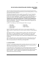
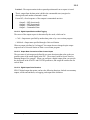
3.2.1.2 Functional Structure of Digital Input Points
Manual
Input
From
PLC
Raw
State
Conversion
to PV
Auto
PV
PV
Alarming
Substituted
Figure 3-1 — Functional Diagram, Digital Input Data Points
1828
3.2.1.3 Types of Digital Inputs
The TDC 3000 System handles change detection, sequence-of-events, and notified-status
digital inputs. EPLCGs provide only notified status digital inputs which record changes of
the digital input state.
3.2.1.4 Functional Description
3.2.1.4.1 Input Detection
Input Voltage Levels, Contact Bounce Filtering—The emulated DHP itself has no input
signal conditioning boards, but the programmable controller it interfaces may have them.
DHP Scanning Rate—The EPLCG scans its digital inputs with a free-running scanner that
scans as fast as its processor and communication network can.
3.2.1.4.2 Conversion of Raw Contact Inputs to the PV
The PV for a digital input point has two states, such as on/off or open/closed. You
configure a descriptor for each of the two PV states in the STATE1 and STATE2
parameters (if you need more information, refer to subsection 3.2.4), and when you do,
you relate those states to the states of the raw input wired from the PLC. These descriptors
represent the state of each digital input when they appear on US displays.
EPLC Gateway Control Functions
3-9
9/97
3.2.1
3.2.1.4.3 PV Source Selection for Notified-Status Inputs
Parameter PVSOURCE indicates the source of the digital input PV. When PVSOURCE
contains Auto, the PV is an input from the PLC. When it contains Man, the source is an
operator at a US. When it contains Sub, a user-written program or a continuous-control
data point provides the PV (see subsection 3.1.7.)
3.2.1.4.4 Digital Input Alarms
Digital point alarms are defined under subsection 3.4.
3.2.1.4.5 Event-Initiated Processing
You can configure digital input points for event-initiated processing (EIP—See subsection
4.2 in System Control Functions). EIP occurs for each alarm and each return-to-normal.
It also occurs when the PV changes state.
3.2.1.4.6 Digital Input Point Functions
These are digital input functions for EPLCGs:
•
•
•
•
•
Input Acquisition
PV Conversion
PV Source Selection
Alarming: Off Normal, Change of State
EIP
Note: Inputs are by a free-running scanner.
3.2.1.5 Initialization of Digital Inputs
Digital input data points are initialized when the emulated DHPs are restarted. The
emulated DHPs don't initialize in the sense that some hiway-based boxes do. DHPs
"initialize" to the state of the inputs first acquired when the emulated DHP goes from the
reset state to the processing state. When an emulated DHP is reset, the PV is not available
to the EPLCG.
3.2.1.6 Digital Input Point Parameter Descriptions
Refer to the EPLC Gateway Parameter Reference Dictionary, for the full names, value
ranges, default values, value types, and access levels for these parameters.
3.2.2 EPLCG Digital Output Data Points
A digital output data point writes a single digital state to a location in a PLC. A dual digital
output point writes a single digital state to two locations in a PLC.
EPLC Gateway Control Functions
3-10
9/97
3.2.2
For the emulated DHP, the number of digital output data points is limited by the number of
I/O slots that are configured for digital outputs. There can be up to 8 for each slot and a
maximum of 30 slots for a DHP.
There may be some limitation in number of digital output points that the EPLCG can
handle, because of the number and mix of boxes on the hiway, and the types of points in
the boxes.
The number of momentary (doorbell) digital output points is limited to 500 for the EPLCG.
3.2.2.1 Functional Structure
Man
Cas
Conversion
to Raw State
Output
State
(Source Determined
by Mode)
Digital
Output
Output
to
PLC
(Source writes one of
two output states.)
Figure 3-2 — Functional Diagram, Digital Output
1829
3.2.2.2 Digital Output Functional Description
3.2.2.2.1 Digital Output Behavior
Digital outputs have one of two types of behavior:
Momentary (doorbell)—Outputs can be sent from a Universal Station. A momentary
output stays in the specified position as long as the operator or engineer continues to
press the appropriate key.
For a US, a variable length sequence is transmitted, depending on how long the output
change key (UP or DOWN triangle) is depressed. The sequence is as follows:
Activate Sequence Output2 = Commanded State
Output1 = Commanded State
Activate Sequence is repeated each second (by HG function) if output key is kept
depressed.
The Deactivate Sequence is executed when the ouptut change key is released.
Deactivate Sequence Output2 = OFF (deactivated)
Output1 = OFF (deactivated)
Therefore, the minimum sequence is 4 outputs, for a brief depression of the ouptut
change key. Note: Momentary outputs in a 2-output composite point typically result
in a PV state of BADPV or INBETWN, which is undesirable.
EPLC Gateway Control Functions
3-11
9/97
3.2.2
Latched—The output remains in the requested position until a new request is issued.
That is, output from the data point is held in the commanded state (energized or
deenergized) until another command is issued.
For an HG, a fixed sequence of four outputs is transmitted one time:
Output2 = OFF (deactivated)
Output1 = OFF (deactivated)
Output2 = Commanded State
Output1 = Commanded State
3.2.2.2.2 Digital Output Modes and Red Tagging
The source of the output request is determined by the mode, which can be:
• CAS—Output state specified by another data point or by a user-written program
• MANual—Output state specified through a Universal Station
When an output is defined as "red tagged," the output does not change despite output
requests from a Universal Station or from a user-written program.
3.2.2.2.3 Output State Conversion to Raw Contact Output
The two states of each output are defined by two state descriptors that relate to the two
possible states of the stored digital in the PLC. These states could be Open/Closed or
Running/Stopped, for example. When you configure a digital output point, you provide
the descriptors in the STATE1 and STATE2 parameters, and assign the contact state for
each of them.
3.2.2.2.4 Digital Output Point Functions
EPLCG digital output data points can have the following functions: latched or momentary
outputs, modes and attributes, red tagging, and output state definition.
EPLC Gateway Control Functions
3-12
9/97
3.2.2
3.2.2.3 Digital Output Processing
A request for a digital output change is processed at the next processing pass of the
emulated DHP and before the start of a new scan request. The requests are checked against
the mode, attribute, and red-tag restrictions by the EPLCG. Once an output state change is
affected by the DHP, the DHP does a read-back check to verify the actual output state on
the next data scan, and all subsequent data scans change which detect PLC logic.
3.2.2.4 Digital Output Initialization
A digital output point is initialized when it is restarted. During initialization, the EPLCG
reads the actual state of the output and set their internal output state to the corresponding
state. The emulated DHP reads the state of the coil or defined memory location in the
programmable controller. The mode in the emulated DHP is set to the same mode as before
the point was initialized.
3.2.2.5 Digital Output Parameter Descriptions
Refer to the EPLC Gateway Parameter Reference Dictionary for the full names, value
ranges, default values, value types, and access levels for each parameter.
3.2.3 EPLCG Digital I/O Composite Data Points
A digital I/O composite data point consists of one or two digital inputs and one or two
digital outputs with the same tag name. The input slot (and subslots) and the output slot
(and subslots) must be in the same emulated DHP. Typically, the inputs show the direct or
indirect result of the digital output, on the PLC that the output(s) is wired to.
NOTE
When you view the structure of a composite point with dual inputs or outputs on the Box
Point Summary or Unit Point Summary display, the second part of the dual point doesn’t
appear in the table. You should assume that it resides in the next consecutive slot because it
must be configured there.
EPLC Gateway Control Functions
3-13
9/97
3.2.3
3.2.3.1 Functional Structure
See Figure 3-3.
3.2.3.2 Functional Description
3.2.3.2.1 Digital I/O Composite Data Point—I/O Combinations
Each digital I/O composite data point can be configured for one or two inputs
(NMBRINPT) and one or two outputs (NMBROUT).
The functions for the inputs and outputs are essentially the same as for the individual inputs
(3.2) and outputs (3.3).
Raw
State
Input
Raw
State
Input
Manual
PVAUTO
PV
Auto
PV
Alarming
Alarms
Sub
Value in
PVSOURCE
Inputs
Outputs
Value in
MODE
Operator
at a US
Data Point
or
User-Written
Program
Man
Conversion:
Output State
to Digital Output
Output
State
Cas
Digital
Output
Digital
Output
Figure 3-3 — Functional Diagram, Digital I/O Composite Data Point
1830
3.2.3.2.2 Input Detection for Digital I/O Composite Points
Input detection is the same as described under subsection 3.2.1.4.1 except that only
notified-status inputs are accepted by digital I/O composite data points.
EPLC Gateway Control Functions
3-14
9/97
3.2.3
3.2.3.2.3 Conversion of Input(s) to PV(s)
The PV(s) represent the current state(s) of the input signal. A single input can generate two
PVs. Dual inputs can generate four PV states. The PV for a digital input point has two
states like on/off or open/closed. You configure a descriptor for each of the two PV states
in the STATE1 and STATE2 parameters (see subsection 3.2.4), and when you do, you
relate those states to the states of the raw digital acquired from the PLC. These descriptors
represent the state of each digital input when they appear on US displays. If dual inputs are
used, the descriptors for the remaining two states default to Bad and InBetwen.
3.2.3.2.4 PV Source Selection for Digital Composite I/O Points
Parameter PVSOURCE indicates the source of the digital input PV. When PVSOURCE
contains Auto the PV is derived from the PLC. When it contains Man, the source is an
operator at a US. When it contains Sub, a user-written program or a continuous-control
data point provides the PV (see subsection 3.1.7.)
3.2.3.2.5 Alarming
Digital point alarms are defined under subsection 3.2.4.
3.2.3.2.6 Event-Initiated Processing for Digital I/O Composite Points
You can configure digital I/O composite points for event-initiated processing. EIP occurs
when an alarm is detected or on a return-to-normal. See subsection 4.2 in System Control
Functions.
3.2.3.2.7 Modes/Attributes/Red Tagging
The source of an output request is indicated by the value in the MODE parameter, which
can be:
• CAS—Output state specified by another data point or by a user-written program
• MANual—Output state specified through a Universal Station
When an output is defined as "red tagged," the output does not change, despite output
requests from a Universal Station or from a user-written program.
The attributes determine if an operator (Oper) or a user-written program (Prog) can change
the mode and the PV when in Manual mode.
3.2.3.2.8 Output State Conversion to Raw Contact Output
The output to the PLC can have two states. These correspond to the two possible states of
the memory location of the PLC, one/zero or true/false. You configure a descriptor for
each of the two states in parameters STATE1 and STATE2. The descriptors relate the state
of the output to the state at the output terminals ("raw" outputs).
EPLC Gateway Control Functions
3-15
9/97
3.2.3
3.2.3.2.9 Digital I/O Composite Point Functions in DHPs
The following are digital composite point functions in EPLCGs:
•
•
•
•
•
•
•
Input Acquisition
PV Conversion
PV Source Selection
Alarms (see subsection 3.2.4)
EIP, Output Behavior: Latched, Pulsed; Modes/Attributes
Red Tagging
Output State Conversion
Note: Inputs are scanned by a free-running scanner.
3.2.3.3 Processing of Digital I/O Composite Points
Outputs are processed as described under subsection 3.2.2.4.
3.2.3.4 Initialization
Initialization is as described under subsection 3.2.1.5 and subsection 3.2.2.5.
3.2.3.5 Digital I/O Composite Parameter Descriptions
Refer to the EPLC Gateway Parameter Reference Dictionary for the full names, value
ranges, default values, value types, and access levels for each parameter.
EPLC Gateway Control Functions
3-16
9/97
3.2.4
3.2.4 DIGITAL ALARMS
The types of digital alarms are:
• Change-of-state alarms—The alarm is detected when the state of a digital input point
changes in either direction. This alarm is cleared from the Alarm Summary Display
when the alarm is acknowledged.
• State alarms—The alarm is generated when the input point is in the state contained in
the DIGALFMT parameter. The states for this alarm are State 1, State 2, Input 1, Input
2, Either, and Both. This alarm remains on the Alarm Summary Display until the point
is no longer in the alarm state.
• Command disagree alarms—These alarms apply to only digital composite points. The
alarm is generated when the point has been commanded output to go to a state, and after
a user-defined time, the input state does not agree with the commanded state.
For state, change-of-state, and command disagree alarms, the alarm descriptor that appears
on the Alarm Summary Display is the actual state of the digital PV, which can be the string
value (self-defined enumeration) in any of these parameters: STATE1, STATE2,
ZZTEXT, or the complement of ZZTEXT. If DIGALFMT contains Either and Both boxes
for the point on the Group or Detail Display are lit, the state shown on the Alarm Summary
Display is that of the first box lit.
You configure the types of alarms for these points in parameter DIGALFMT. Details of the
alarm options, alarm conditions, and the effect on the Group and Detail displays for these
points are provided under the listing for DIGALFMT in the EPLC Gateway Parameter
Reference Dictionary. The alarm formats that can be configured for each type of digital
point are listed on the configuration forms and appear on the Data Entity Builder's
parameter entry displays (PEDs). The formats for EPLCG (DHP) digital points are:
•
•
•
•
State1—State 1 alarm
State1—State 2 alarm
Chngofst—Change-of-state alarm
Cmmdis—Command disagree alarm
The following parameters are also related to digital alarms:
•
•
•
•
INPDIR—Input direction
OUTIND—Output indication
ZZTEXT—State 00 text (neither box lit)
NCMPTXT1 and NCMPTXT2—Noncomplementary inputs text
3.2.4.1 Summary of Digital States and Alarms
The following chart shows which digital alarm types apply to single input and dual input
points. The command disagree alarm applies only to digital I/O points.
Applicable Alarm Type
Noalm (no alarm)
State1
State2
Chngofst (change of state)
Cmmdis (command disagree)*
__________
Single Input
Yes
Yes
Yes
Yes
Yes
Dual Input
Yes
Yes
Yes
*Only with a composite output point.
EPLC Gateway Control Functions
3-17
9/97
3.2.4
For single digital inputs
State Presentation
Input State State Text
(PV)
Parameter
0 1
1 0
Boxes
Lit
STATE1
STATE2
LCN
Ordinal
State Description on Alarm Summary Display
State Alarm
Command Disagree
0
1
Lower
Upper
State 1
State 2
STATE1
n/a
n/a
STATE2
State 1
n/a
STATE2
State 2
STATE1
n/a
Reverse Indication
Direct Indication
For dual digital inputs
State Presentation
LCN
Boxes
Ordinal
Lit
Input State State Text
(PV)
Parameter
00
01
10
11
ZZTEXT
STATE1
STATE2
CZZT
11
10
01
00
None
Lower
Upper
Both
State Description on Alarm Summary Display
State Alarm
Commd Disagree
Input 1 Input 2 Either Both State 1 State 2
n/a
n/a
ST2
ST2
0
1
2
3
n/a
ST1
n/a
ST1
n/a n/a ZZTEXT ZZTEXT
ST1 n/a
n/a
STATE1
ST2 n/a
STx CZZT CZZT
CZZT
Reverse Indication
Direct Indication
For single digital outputs
State Presentation
Output State State Text
(OP)
Parameter
0 1
1 0
STATE1
STATE2
Boxes
LCN
Lit
Ordinal
Lower
Upper
0
1
What Activates Output
with Group or Detail Display
Down Arrow
Up Arrow
Reverse Indication
Direct Indication
For dual digital outputs
State Presentation
Output State State Text
(OP)
Parameter
00
01
10
11
11
10
01
00
"NONE"
STATE1
STATE2
"BOTH"
Boxes
Lit
None
Lower
Upper
Both
LCN
Ordinal
0
1
2
3
Reverse Indication
Direct Indication
What Activates Output
with Group or Detail Display
(Not Possible)
Down Arrow
Up Arrow
(Not Possible)
11761
In this chart, dual input states are given in input 1, input 2 order—input 1 is the subslot specified
and input 2 is that subslot plus one. These abbreviations are used for parameter names and
values:
ST1 and ST2 mean STATE1 and STATE2. ZZT means ZZTEXT. CZZT means the complement
of the value in ZZTEXT. The integers in the "LCN Ordinals" column are values that can be
accessed by upper-level processors through CGs to determine the input states of digital points.
EPLC Gateway Control Functions
3-18
9/97
3.3
3.3 EPLCG COUNTER DATA POINTS
The EPLCG Counter point is primarily a communication mechanism for exchanging data between
the TPS Network and a PLC, NOT a control point. Thus, many typical counter functions are not
supported, and some TPS system point functions are not supported, such as trending and some
alarm features.
1. The only DHP Counter point parameter written to the PLC register is OP (after dividing by
AVCONV scale factor).
2. The value read from the PLC register is available in the AV and OP parameters for the Counter
point, after scaling by the AVCONV parameter.
3. There is no PV (Process Variable) parameter for a Counter point.
An EPLCG Counter point provides access to a PLC database register, using Modbus Function
Code 03, “Reading Holding Register.” The register accessed in the PLC need not be a counter or
timer, but the PLC register value must be a positive integer in range 0 - 65535. The PLC inputs are
typically accumulated values from instruments like pulse-type flow meters, speedometers, or event
counters, but can be any integer stored by the PLC in the defined location.
EPLCG counter data points use counter slots in emulated DHPs. Each DHP slot can have eight
counters. The PLC register address must be configured in DHP Counter point parameter
PCADDRI1.
An EPLCG counter point can be used to write a value to a PLC location. The PLC can overwrite
this location, and it can treat the location as a supervisory control input.
3.3.1 Functional Structure, EPLCG Counter Point
The structure of a EPLCG counter is shown on Figure 3-4.
Input
or Ladder/Program store
1 1 1 1 1 0 0 0
in PLC
x
AVCONV
= 9 9 9 9 9 . 9 9 AV
in EPLCG
PRESET
AVFORMAT
Preset Value
Integer Accumulated Value
"PLC" x "AVCONV" = "AV"
Decimal Position for AV Value
AV
Accumulated Value
11749-A
Figure 3-4 — Functional Diagram, EPLCG Counter
EPLC Gateway Control Functions
3-19
9/97
3.3.2
3.3.2 Counter Functions
The EPLCG scan puts the content of a PLC register into the Accumulated Value (AV) and
Output (OP) parameters, after scaling by the Accumulated Value Conversion factor
(AVCONV) parameter. Setpoint (SP) and PRESET parameters can be changed by an
operator, but are forced to the same value. An operator may change the PLC register using
the OP target, but a program must write to the AV parameter.
3.3.3 EPLCG Counter Parameters
For information on the functions, value types, ranges, and access levels of these
parameters, refer to the EPLC Gateway Parameter Reference Dictionary, and to the EPLC
Gateway Configuration Form Instructions.
3.3.4 EPLCG Counter Processing
Emulated DHP counters are updated by the free-running scan from PLC memory.
3.4 EPLCG HIWAY AND BOX/SLOT DATA POINTS
EPLCG hiway data points contain parameters that define the EPLCG’s emulated Data
Hiway to the system. EPLCG box data points contain parameters that define the emulated
DHPs (“boxes” on the emulated hiway) and assign a box number or hiway address to each
DHP. One box point is configured for each of the up to eight emulated DHPs. Both hiway
and box points are built with the Data Entity Builder. To access the Parameter Entry
Displays for these points, on the Engineering Main Menu, select HIWAY GATEWAY, then
on the next menu select HIWAY CONFIG or BOX/SLOT CONFIG.
3.4.1 Hiway Point Parameters
For information on the functions, value types, ranges, and access levels of these
parameters, refer to the EPLC Gateway Parameter Reference Dictionary, and to the EPLC
Gateway Configuration Form Instructions.
3.4.2 Box/Slot Data Point Processing
Box data points are not scheduled for processing, nor processed at regular intervals like
other data points are. Their parameters are updated when necessary by the EPLCG and the
boxes. Hiway data points and box data points must be configured for EPLCGs. Even
though the emulated DHPs in an EPLCG are not physical boxes on a physical Data Hiway,
hiway and box data points must still be configured for them.
Performance and communication information is maintained by the EPLCG’s emulated
DHPs. These statistics may be obtained by using SMCC. For more information, refer to
EPLC Gateway Planning, Installation, and Service.
EPLC Gateway Control Functions
3-20
9/97
3.4.3
3.4.3 Box/Slot Data Point Parameters
For information on the functions, value types, ranges, and access levels of these
parameters, refer to the EPLC Gateway Parameter Reference Dictionary, and to the EPLC
Gateway Configuration Form Instructions.
3.4.4 Box/Slot Point Names
Box Points have reserved-entity names, which are automatically established by the Data
Entity Builder as you build the points. Users and user programs can refer to box point
parameters through the reserved-entity names. For example:
$HY02B05.BOXSTAT
The box status parameter
Box number 05
Data Hiway 02
Identifies this as a reserved entity
11766
EPLC Gateway Control Functions
3-21
9/97
EPLC Gateway Control Functions
3-22
9/97
Index
Topic
Section Heading
Alarms
Analog Points
Critical
Critical Status
Digital
Limits
Allen-Bradley PLCs
Analog Input Points
Analog I/O Data Points, EPLCG
Point Addressing
First Level Processing
Second Level Processing
Analog Output Data Point Modes
B12E (TDC System format)
Backup, EPLCG
Box (DHP) Control States
Box/Slot Data Point
Names
Parameters
Processing
Relating to PLCs
Boxes (Emulated DHPs)
Functions Related to
Capacity, Data Point, EPLCG
Clamping
Options, PV, Analog Points
Composite Data Points
Composite Points in One Box
EPLCG Digital I/O
Contact-Cutout Secondary Points
Control Time-out Function
Counter Data Points
Functional Structure
Processing
Critical Alarm Status
DHP (Emulated)
Control States
Status
Startups
Digital Data Points
Alarms
Composite Data Points
Digital Input Points
Digital Output Data Points
"Doorbell" Points
Momentary Points
Summary of States and Alarms
"Doorbell" Digital Points
Emergncy Alarms
Entities, Reserved
EPLC Gateway Control Functions
3.1.9
2.7.3
2.7.3
3.2.4
3.1.10
2.8.2.2
2.7.5
3.1
3.1.12
3.1.4
3.1.7
3.1.8
3.1.4.1
2.4
2.3.9
3.4
3.4.4
3.4.3
3.4.2
2.6.1
2.8.1
2.7
2.8.1.5
3.1.7
2.7.2
3.2.3
2.7.7
2.8.1.2
3.3
3.3.1
3.3.4
2.7.3
2.3.9
2.3
2.8.1.1
3.2.4
3.2.3
3.2.1
3.2.2
2.7.4
2.7.4
3.2.4.1
2.7.4
2.7.3
2.6.2
Index-1
9/97
Index
Topic
Section Heading
Errors
Avoiding Errors
Error Codes
Errors on Input and Output Requests to PLCs
Event Initiated Processing
Analog Points
Points with EIP
Fail-COM Box Status
Fail-HDW Box Status
Failover Scenario
Fifty Points with Critical Alarm Status
Format
Decimal (Analog values)
TDC System (B12E)
Functions
EPLCG, Special
Related to DHPs
Special, Related to PLCs
Time-out, Control
General Parameter Access
Handling
Reverse-Acting Transmitter
Hiway Gateways
Hiway Point Parameters
Hiway States
Idle-SF, Idle-PF
Input Points
Analog
Digital
Keep-Alive Addressing
Modbus Protocol
Modes and Attributes
Modes, Data Point, Analog Output
Modicon PLCs
Momentary ("Doorbell") Digital Points
Multifunction Controller
Names, Box Points
Parameters, EPLCG
Analog Composite
Analog Input
Analog Output
Box/Slot
Counter
Digital Composite
Digital Input
Digital Output
Hiway Point
EPLCG Parameters, Configuration
EPLC Gateway Control Functions
Index-2
2.5.1
2.5
2.5.2
3.1.9
2.7.6
2.3.5
2.3.6
2.4.1
2.7.3
3.1.5.2
3.1.4.1
2.8
2.8.1
2.8.2
2.8.1.2
2.8.1.3
2.8.1.6
3.4.1
2.2
2.3.4
2.7.5
3.2.1
2.8.2.3
2.6.4
3.1.8
2.8.2.1
2.7.4
3.4.4
3.1.9.1
3.1.3.1
3.1.8.1
3.4.3
3.3.3
3.2.3.7
3.2.1.6
3.2.2.5
3.4.1
2.5, 2.6.3
9/97
Index
Topic
Section Heading
PLCs
Allen-Bradley
Modicon
PLC Addressing
Relating EPLCGs to
EPLCG Counter Point
Functional Structure
Parameters
Processing
Points
Analog Input
Analog I/O
Contact Cutout Secondary
Event-Initiated Processing, Points with
Composite Points in One Box
Fifty Points with Critical Alarm Status
Momentary “Doorbell” Digital Points
Point Alarming, Analog Points
Point Capacity, EPLCG
Point Processing, Analog I/O
Point Types
Analog
Digital
Point Types,
Process Variable
Process-Connected Subsystems
Special Functions Related to
Processing
Analog I/O Point
Analog Points, Order of
Counter
Event-Initiated, Analog Points
First Level of Analog I/O Points
Second Level of Analog I/O Points
PV
Clamping Options, Analog Points
Range and Clamping, Analog Points
Range, Analog Points
Source Selection
Source Selection, Analog Points
Value Status
PVEUHI, PVEULO
Range, PV, Analog Points
Range Codes, PLC
References
Reset Box Status
Reverse-Acting Transmitter Handling
RNGCODE0,1,2
Run State
Run-PF
Run-SF
EPLC Gateway Control Functions
Index-3
2.8.2.2
2.8.2.1
2.6.1
3.3.1
3.3.3
3.3.4
2.7.5
3.1
2.7.7
2.7.6
2.7.2
2.7.3
2.7.4
3.1.9
2.7.1
3.1.12
3.1.1
3.2.1.3
see PV
2.8.2
3.1.11
3.1.3
3.3.4
3.1.9
3.1.4
3.1.5
3.1.7
3.1.7
3.1.7
2.8.1.4
3.1.7
2.8.1.7
3.1.5.1
3.1.7
3.1.4.1
1.1
2.3.7
2.8.1.6
3.1.4.1
2.3.1
2.3.3
2.3.2
9/97
Index
Topic
Section Heading
Scenario, EPLCG Failover
Secondary Points, Contact-Cutout
Selection, PV Source, Analog Points
Selection, PV-Source
Software Upgrades
Source Selection, PV, Analog Points
Special EPLCG Functions
Startups, DHP
States
Box (DHP) Control
Hiway
Run
Status
Emulated DHP
PV Value
Target Value
Total EPLCG Point Capacity
Transmitter Handling, Reverse-Acting
Uncertain Box (DHP) Status
Value Status, PV
EPLC Gateway Control Functions
Index-4
2.4.1
2.7.7
3.1.7
2.7.1.4
2.8.3
3.1.7
2.7
2.8.1.1
2.3.9
2.2
2.3.1
2.3
2.8.1.7
3.1.5.3
2.7.1
2.8.1.6
2.3.8
2.8.1.7
9/97
FAX Transmittal
FAX No.: (602) 313-4842
TO:
Total fax pages:
(including this page)
G. Cacciatore
Reader Comments
Title of Document:
Enhanced Programmable Logic Controller Gateway Control Functions
Document Number:
EP09-400
Issue Date: 9/97
Comments:
Recommendations:
FROM:
Name:
Date:
Title:
Company:
Address:
City:
State:
Telephone:
FAX:
ZIP:
You may also call 800-822-7673 (available in the 48 contiguous states except Arizona; in Arizona dial
602-313-5558, or write to:
Honeywell Inc.
Industrial Automation and Control
Automation College
2820 West Kelton Lane
Phoenix, AZ 85023-3028
Industrial Automation and Control
Automation College
2820 W. Kelton Lane
Phoenix, AZ 85023-3028
Helping You Control Your World