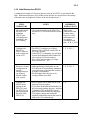
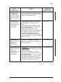
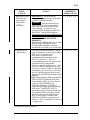
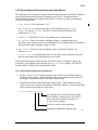
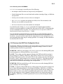
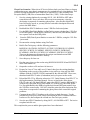
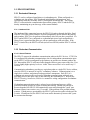
1
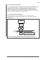
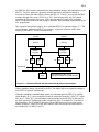
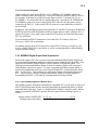
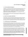
Enhanced Programmable
Logic Controller Gateway
Implementation Guidelines
EP12-400
Implementation
EPLC Gateway
Enhanced Programmable
Logic Controller Gateway
Implementation Guidelines
EP12-400
Release 430
9/97
Copyright, Trademarks, and Notices
© Copyright 1992 - 1997 by Honeywell Inc.
Revision 02 – September 20, 1997
While this information is presented in good faith and believed to be accurate,
Honeywell disclaims the implied warranties of merchantability and fitness for a
particular purpose and makes no express warranties except as may be stated in its
written agreement with and for its customer.
In no event is Honeywell liable to anyone for any indirect, special or consequential
damages. The information and specifications in this document are subject to
change without notice.
Honeywell, TotalPlant, and TDC 3000 are U.S. registered trademarks of Honeywell Inc.
Other brand or product names are trademarks of their respective owners.
About This Publication
This publication summarizes the Enhanced Programmable Logic Controller Gateway
(EPLCG) implementation process, guides you to procedures and references you need to
implement EPLCGs, defines the hiway and box/slot entities you must build for each
EPLCG, and describes EPLCG operation considerations in implementing and using
EPLCGs.
This publication supports Release 430.
EPLCG Implementation Guidelines
9/97
EPLCG Implementation Guidelines
9/97
Table of Contents
1
INTRODUCTION
1.1
1.2
1.2.1
1.2.2
1.3
Summary of EPLCG Implementation Tasks
References
References for Engineering Activities
References for Hardware Implementation
EPLCG Implementation Dependencies
2
HIWAY AND BOX/SLOT CONFIGURATION
2.1
2.2
2.2.1
2.2.2
2.3
2.4
2.4.1
2.4.2
2.4.3
2.5
2.5.1
2.5.2
2.5.3
2.5.4
2.5.5
Purpose of the Hiway and Box/Slot Entities
Hiway and Box/Slot Entities to be Built
Hiway Entities
Box/Slot Entities
Order for Hiway and Box/Slot Entity Building
Hiway Configuration
Hiway Number
Hiway Traffic Director Functions
Sequence-of-Events Synchronization
Box/Slot Configuration
EPLCG Data Hiway Addresses
Emulated DHP Hiway Address Assignments
EPLCG and DHP Box Assignment
Event Processing
Change Detection
3
EPLCG OPERATIONAL CONSIDERATIONS
3.1
3.1.1
3.2
3.2.1
3.2.2
3.2.3
3.2.4
3.2.5
3.2.6
3.3
3.3.1
3.3.2
3.3.3
3.3.4
3.3.5
The EPLCG Subsystem
DHP Point Planning Guidelines
Loading, Saving, and Restoring of EPLCG Data
EPLCG Initial Startup or Restart
Initial Startup of a EPLCG
Saving of EPLCG and DHP Data
Restoring EPLCG and DHP Data
Recovering from Checkpointing and Loading Errors
Recovery from DHP Point Configuration Errors
EPLCG Functions
Redundant Gateways
Redundant Communication
Allen-Bradley Communication Redundancy - Additional Features
Nonredundant Communication to Allen-Bradley PLC-5
MODBUS Digital Outrput Scan Suppression
4
EPLCG PERFORMANCE CONSIDERATIONS
41
4.2
4.3
Factors Limiting Performance
Effects of Database Composition
Adjusting a EPLCG for Performance
I
INDEX
EPLCG Implementation Guidelines
i
9/97
EPLCG Implementation Guidelines
ii
9/97
1
INTRODUCTION
Section 1
This section summarizes the Enhanced Programmable Logic Controller Gateway implementation
tasks, lists publications that you will refer to in order to implement EPLCGs, and describes
implementation dependencies.
1.1 SUMMARY OF EPLCG IMPLEMENTATION TASKS
While most of the the information in this publication relates to Enhanced Programmable
Logic Controller Gateway EPLCG) functions, EPLCG data points, and EPLCG operating
considerations, other implementation activities must also be completed to make the EPLCG
functional. The Engineering Personality activities listed below may be affected by the
implementation of a EPLCG or must be used to implement a EPLCG.
See subsection 1.2 for references to instructions for each of the activities listed below.
Activities named in THIS TYPEFACE are activated by targets on the Engineering
Personality Main Menu.
•
UNIT NAMES—The process units defined for each EPLCG data point are
established in this activity.
•
AREA NAMES—The area name and descriptor for any units with EPLCG points that
are assigned to an area are established in this activity.
•
LCN NODES—Identifies and defines the nodes on the Local Control Network. In
the case of EPLCGs, this activity defines the node numbers for the EPLCGs and
the process network number for the EPLCGs’ emulated Data Hiways. Note that
because the EPLCG is supported by the Hiway Gateway software, you configure
EPLCGs as if they were HGs.
•
VOLUME CONFIGURATION—The EPLCG (HG) checkpoint volume(s), &7np is
established in this activity. Volume &7np must have adequate storage space to
accommodate the EPLCG checkpoint data, including the data for its emulated DHPs
(boxes).
•
APPLICATION MODULE—Any AM points that are members of a control strategy
that includes EPLCG points are built in this activity. Connections to the EPLCG
points are defined in tagname.parameter form.
•
HIWAY GATEWAY—The Hiway point which defines the EPLCG’s emulated Data
Hiway and the Box/Slot points that define the functions and content of the emulated
DHPs are built in this activity. Also, the EPLCG data points are built in this
activity.
•
PICTURE EDITOR, FREE FORMAT LOGS, BUTTON CONFIGURATION—Any of
pictures, logs, and buttons built by these activities can access EPLCG points, once
the points are built and loaded.
EPLCG Implementation Guidelines
1-1
9/97
1.2
•
HM HISTORY GROUPS—EPLCG data point values for which continuous history is
to be collected are defined in this activity, by assigning them to specific HM history
groups.
•
AREA DATA BASE—This activity defines how and where data for data points,
including EPLCG data points, are used and displayed in a given process area. The
area database is the database loaded into a Universal Station, so that the database
defines the process area monitored and controlled through the US.
•
Control Language (CL)—The EPLCG does not have a CL program feature, but
CL/AM programs can read from and write to EPLCG data points.
•
Ladder Logic Programming—The make and model of the PLC(s) connected to the
EPLCG can widely differ, so the Honeywell IAC publications do not provide
information for ladder logic programming. Consult the manuals provided by the
PLC vendor(s).
1.2 REFERENCES
1.2.1 References for Engineering Activities
•
UNIT NAMES and AREA NAMES
Network Form Instructions in the Implementation/Startup and Reconfiguration 1 binder.
Network Data Entry in the Implementation/Startup and Reconfiguration - 1
binder.
•
VOLUME CONFIGURATION—Section 7 of the Engineer’s Reference Manual in the
Implementation/Startup and Reconfiguration - 2 binder. For the EPLCG
checkpoint volume(s), follow the instructions for HG checkpoint volumes.
•
APPLICATION MODULE
Application Module Control Functions in the Implementation/AM - 1 binder.
Application Module Algorithm Engineering Data in the Implementation/AM - 1
binder.
Application Module Parameter Reference Dictionary in the Implementation/AM 1 binder.
Data Entity Builder Manual in the Implementation/Engineering Operations - 1
binder.
•
HIWAY GATEWAY EPLCG)
System Control Functions in the Implementation/Startup & Reconfiguration - 2
binder.
EPLCG Implementation Guidelines
1-2
9/97
1.2.2
Enhanced Programmable Logic Controller Gateway Control Functions in the
Implementation/EPLC Gateway binder.
Enhanced Programmable Logic Controller Gateway Parameter Reference
Dictionary in the Implementation/EPLC Gateway binder.
Data Entity Builder Manual in the Implementation/Engineering Operations - 1
binder.
•
PICTURE EDITOR, FREE FORMAT LOGS, BUTTON CONFIGURATION
Instructions for these activities are in the Implementation/Engineering
Operations - 2 binder.
•
HM HISTORY GROUPS
HM History Group Form Instructions in the Implementation/Engineering
Operations - 1 binder.
Data Entity Builder Manual in the Implementation/Engineering Operations - 1
binder.
•
AREA DATA BASE
Area Form Instructions in the Implementation/Engineering Operations - 1
binder.
Data Entity Builder Manual in the Implementation/Engineering Operations - 1
binder.
1.2.2 References for Hardware Implementation
1.2.2.1 Site Planning
LCN Site Planning manual in the System Site Planning binder.
Enhanced Programmable Logic Controller Gateway Planning, Installation, and Service in
the Implementation/EPLC Gateway binder.
1.2.2.2 Installation and Checkout
Enhanced Programmable Logic Controller Gateway Planning, Installation, and Service in
the Implementation/EPLC Gateway binder.
1.2.2.3 Service
Five/Ten-Slot Module Service in the LCN Service-1 binder (Enhanced Programmable
Logic Controller Gateway).
Enhanced Programmable Logic Controller Gateway Planning, Installation, and Service in
the Implementation/EPLC Gateway binder.
EPLCG Implementation Guidelines
1-3
9/97
1.3
1.3 EPLCG IMPLEMENTATION DEPENDENCIES
Figure 1-1 shows which EPLCG implementation tasks depend on information entered in
other tasks. This figure does not necessarily dictate the order in which the tasks must be
completed, but it does show all dependencies that must be satisfied before the EPLCG can
be fully operational.
CONSOLE NAMES
AREA DATA BASE
AREA NAMES
PLC Address Assignments and
Ladder Logic Programming
Process Operations
Standard Operational
Displays and Reports
VOLUME CONFIGURATION
PICTURE EDITOR
HG (EPLCG) Checkpoint
Volume(s)
FREE FORMAT LOGS
BUTTON CONFIGURATION
User Volumes for Storage of
.EB Files or IDFs
User-Built Schematics
Free Format Logs
Buttons
Cont. Hist. Volumes
History Collection
and Retrieval
UNIT NAMES
All
LCN NODES
HIWAY GATEWAY
HIWAY CONFIG
BOX/SLOT CONFIG
HG PROCESS POINT BUILD
TYPE(s)
Control Language
HM HISTORY GROUPS
11768
Figure 1-1 — EPLC Gateway Implementation Dependencies
EPLCG Implementation Guidelines
1-4
9/97
2
HIWAY AND BOX/SLOT CONFIGURATION
Section 2
This section provides guidelines for building hiway and box/slot configuration entities for each
EPLC Gateway.
2.1 PURPOSE OF THE HIWAY AND BOX/SLOT ENTITIES
Each hiway entity (point) defines for the LCN system, the emulated Data Hiway. Each
box/slot entity defines for the LCN system, the HG (EPLCG) box(es), or one of the
emulated Data Hiway Ports (DHPs) in the EPLCG and each slot in each DHP.
2.2 HIWAY AND BOX/SLOT ENTITIES TO BE BUILT
The EPLCGs in an EPLCG pair always use hiway addresses 02 and 03 on the emulated
Data Hiway. The emulated DHPs in each EPLCG or EPLCG pair always use hiway
addresses 08 through 15. For more information about this addressing scheme, refer to
subsection 2.5 in EPLC Gateway Control Functions in the LCN Implementation/EPLC
Gateway binder.
2.2.1 Hiway Entities
You must build a hiway entity for each EPLC Gateway. Each LCN can have up to 20
process networks. Each Data Hiway or Universal Control Network is one process
network, so the sum of EPLCG Hiway Entities, Hiway entities for Data Hiways connected
to HGs, and UCNs cannot exceed 20. Please note the emulated hiway counts as a process
network, even though is not a physical hiway.
Hiway entities are reserved entities; that is, they are entities whose names are reserved for
use by the system and begins with a dollar sign. The names are in this form:
$HIWAYnn
where nn is the hiway number (01 through 20).
2.2.2 Box/Slot Entities
You must build one box/slot entity for each emulated DHP for which you need to build data
points. Each EPLCG can have up to eight DHPs.
Like hiway entities, box/slot entities are reserved entities; that is, they are entities whose
names begin with a dollar sign, and are reserved for use by the system. The names are in
this form:
$HYnnBxx
EPLCG Implementation Guidelines
2-1
9/97
2.3
where nn is the hiway number (01 through 20) and xx is the hiway box number [2 and
3 for the EPLCG partners (primary and backup) and 8 through 15 for the DHPs].
2.3 ORDER FOR HIWAY AND BOX/SLOT ENTITY BUILDING
The order in which the Hiway and Box/Slot Configuration activities are accomplished is
important. To build them, select HIWAY GATEWAY on the Engineering Main Menu, which
calls up the HG Build Type Configuration Menu. Then select HIWAY CONFIG to build
the hiway entity and BOX/SLOT CONFIG to build the box/slot entities.
Do these activities in this order:
1. HIWAY CONFIG
2. BOX/SLOT CONFIG for this EPLCG pair (HG 2 and 3).
3. BOX/SLOT CONFIG for each DHP in use in this EPLCG pair (8 through 15).
NOTE
When performing this initial load of a DHP’s Box/Slot Configuration, an “A80” Addressing
Error will occur. To clear the error, select Init Addr from the Hiway Command menu
under the Hiway Status Display. Load the DHP Box/Slot Configuration a second time. This
time there should be no errors.
The reserved entities that are defined by these tasks must be loaded in the order listed
above. This means you must use individual Load commands to load the entities separately
in this order, or you must use a Load Multiple command that loads them together in the
proper order. For a Load Multiple command, the order in which the entities are loaded is
specified by the order that the entity names appear in the selection list file.
You could also load these entities from an exception build source file (.EB file). In the .EB
file, entities must be listed in the proper order.
2.4 HIWAY CONFIGURATION
The emulated Data Hiway in an EPLCG is not a physical process network, so the EPLCG
does not have remote or added gateways, as does the Hiway Gateway.
2.4.1 Hiway Number
Each pair of EPLCGs (a primary and secondary) on an LCN is assigned a unique process
network number (01 through 20). The process network number identifies the hiway
database to be used by the EPLCG pair.
EPLCG Implementation Guidelines
2-2
9/97
2.4.2
2.4.2 Hiway Traffic Director Functions
Because there is no physical Data Hiway associated with an EPLCG or EPLCG pair, the
EPLCG has complete control over all transactions on the emulated Data Hiway, so a Hiway
Traffic Director (HTD) is physically impossible and functionally unnecessary. Therefore,
always select ThisHG as the value for parameter HWYHTD in the hiway entity.
2.4.3 Sequence-of-Events Synchronization
The EPLCG does not support sequence-of-events synchronization, therefore, always select
Disable as the value for parameter SOESYNCH in the hiway entity.
2.5 BOX/SLOT CONFIGURATION
The type of box on the Data Hiway (HG for the EPLCG and DHP for the emulated boxes)
is defined in this task, as is each device’s address on the hiway. You must configure a
box/slot entity for each EPLCG in an EPLCG pair and you must configure a box/slot entity
for each DHP for which you intend to build data points.
After selecting BOX/SLOT CONFIG for the BOXTYPE parameter, select HG to configure
an EPLCG box/slot entity; and select DHP to configure a DHP box/slot entity.
2.5.1 EPLCG Data Hiway Addresses
Assign the first EPLCG to hiway address 02 and assign its partner (if present) to hiway
address 03. Confirm that the EPLCI jumper is in the correct position for redundant or
nonredundant EPLCG. Refer to the EPLCG Planning, Installation, and Service manual for
details of EPLCI jumper options.
2.5.2 Emulated DHP Hiway Address Assignments
Assign the emulated DHPs to hiway addresses 08 through 15.
2.5.3 EPLCG and DHP Box Assignment
The EPLCG does not support remote or added gateways, as does the HG, so always
configure ThisHG as the value for the BOXASSN parameter in both the EPLCG box/slot
entities and the DHP box/slot entities.
2.5.4 Event Processing
The emulated DHPs support the generation and reporting of events (Process Alarms,
Process Changes, etc.). The parameter “EVENT PRC” should be set to “ENABLE” to
allow routing of these events through the EPLCG to the LCN.
EPLCG Implementation Guidelines
2-3
9/97
2.5.5
2.5.5 Change Detection
Because there are no other Masters on the Emulated Hiway in the EPLCG, there is no need
to signal or detect changes made by other Masters. The “CHNG FLAG” parameter should
be set to “NOT CONFG.”
EPLCG Implementation Guidelines
2-4
9/97
3
EPLCG OPERATIONAL CONSIDERATIONS
Section 3
This section describes operational characteristics of PLC Gateways (EPLCGs) that you should
consider during EPLCG implementation.
3.1 THE EPLCG SUBSYSTEM
The EPLCG appears to the remainder of the LCN-based system to be a Hiway Gateway
(HG) with a Data Hiway and up to eight Data Hiway Ports. It is supported by the HG
software with no modifications. Therefore, all standard displays, including status
displays, Group displays, Detail displays, and Engineering Personality displays are the
same as if the EPLCG was an HG, including all HG, Data Hiway, and DHP terminology.
US
LCN
PRIMARY EPLCG
HG
PLC
DATA HIWAY
DHP
DHP
PLC
BOXES AND DATA HIWAY ARE EMULATED
BOXES
1
BACKUP
EPLCG
2
PLCs
3
4
5
PLCs
6
PORTS 1 & 2
7
8
Short Haul Modems
or Communication
Interfaces
11567
Figure 3-1— Emulated Data Hiway and DHPs in the EPLCG Subsystem
EPLCG Implementation Guidelines
3-1
9/97
3.1.1
3.1.1 DHP Point Planning Guidelines
Below is a list of items to consider when implementing DHP points in the EPLCG.
1. To avoid potential confusion by operators, do not configure more PC devices in the
DHP box/slot entity ($HYnnBxx) than necessary. Additional devices can be added
later, if needed.
2. Plan or map the PLC addresses carefully and use contiguous PLC addresses as much
as possible for the most efficient data transfers.
3. To avoid interaction between DHP points:
• Do not configure more than one DHP point to access the same PLC memory location.
• Do not use the same slot/subslot for more than one DHP point (tag). Remember that
dual input and dual output points require configuration of the first subslot only,
with the next higher subslot in the same slot automatically assigned to the second
input or output.
4. All points in a DHP slot should have the same PC device index. This will avoid a loss
of view to some points accessing data in a good PLC because of a failure in another
PLC device. A PC device failure will FAIL all points in any DHP slot for which at
least one subslot is configured to access the failed PC device.
5. Note that the DHP box will enter a temporary RESET condition whenever
• the DHP box/slot entity ($HYnnBxx) is loaded;
• a DHP point is loaded to that box (except for load from checkpoint);
• certain DHP parameters are changed from the point detail display. These parameters
include PCADDRxy, SPECIFxy, and PCBITxy, which cause the EPLCG to rebuild
the scan table for data acquisition.
These operations will cause system alarms and may concern operators. A method to
minimize these alarms during configuration is to load DHP points with the DHP box in the
RESET state.
NOTE: Loading multiple DHP points with the DHP box RESET is not recommended for a
new DHP database, since the point configuration and connection to the PLC device are not
checked by the DHP box while in the RESET state. Because any bad point could fail the
entire slot, debugging point configuration errors after Load Multiple is more difficult.
EPLCG Implementation Guidelines
3-2
9/97
3.2
3.2 LOADING, SAVING, AND RESTORING OF EPLCG DATA
3.2.1 EPLCG Initial Startup or Restart
EPLCGs are loaded with software and data through the Gateways and Interfaces display,
which is called up through the System Status display. On the Gateways and Interfaces
display, select the node number (or pair of node numbers) for the EPLCG that is to start up
as the primary EPLCG. Then select the appropriate node loading targets and follow the
prompters to initiate loading of the EPLCG (select OPERATOR PROGRAM to load with the
operating personality). After the status for the primary EPLCG goes to OK, you can initiate
loading of the backup EPLCG. When it is loaded, its status becomes BACKUP.
The EPLCG is loaded with its software personality image and a data image. The data
image consists of previously checkpointed data or null checkpoint (a set of Honeywellprovided checkpoint files with no point data). The data that is loaded from the Gateway
and Interfaces display does not include data for the emulated DHPs, which is loaded or
restored through the Hiway Status display (for more information, see subsection 3.2.2).
CAUTION
Do not try to load both EPLCGs in an EPLCG pair concurrently—one of the EPLCGs will fail.
Complete loading one of the EPLCGs as the primary, then the other EPLCG can be loaded
as the secondary.
For more information about starting or restarting EPLCGs, refer to the information about
loading of gateways and HG modules in Section 15 of the Process Operations Manual in
the Process Operations binder. For instructions for using null-checkpoints in the initial
startup of an EPLCG, refer to Task 18 in the System Startup Guide in the
Implementation/Startup and Reconfiguration - 1 binder.
EPLCG Implementation Guidelines
3-3
9/97
3.2.2
3.2.2 Initial Startup of an EPLCG
A summarized example of 10 steps required to start up an EPLCG are presented in this
table. Publication references given in this section are here for convenience to the startup
effort and some are duplicates of those in the list in subsection 1.2.
STEPS
1 THROUGH 4
NOTES
REFERENCE
PUBLICATIONS
1. Physically install
the EPLCG or
redundant
EPLCG pair;
including power,
grounding, and
LCN cabling.
• The connection between the EPLCG(s)
*Refer to the
and the PLC(s) will be discussed in a later publications listed
step.
by these letters
below for useful
information you
may need to
accomplish each
task: A, B, C, D, E
2. Configure the
EPLCG or
EPLCG pair as a
node or node pair
on the LCN.
• The EPLCG configures as a Hiway
* F, G, H, I, J
Gateway (HG) and looks exactly like an
HG to the operator.
• If the EPLCG is redundant, you will need
to enter the Redundant Node Number ID
(the two digit LCN node number).
• You will be asked to enter a two digit
Hiway number (01 - 20).
3. Perform a volume
configuration to
provide
checkpoint space
on a History
Module within
your system.
• Although having a checkpoint on your
* F, G, H, I, J
LCN network is not absolutely mandatory
(you could store it on removable media), it
is highly recommended.
• Do not simply add a directory to an
existing volume on an HM.
4. Complete the
EPLCI board
pinning in the
EPLCG(s) and
the EPLCG relay
panel pinning on
the back of the
EPLCG(s).
• EPLCG parity can be either odd or even, * A
no parity is not an option.
• If you chose Redundant Allen-Bradley for
the relay panel pinning, the port 1 and port
2 pinning of TS2 on the EPLCI board
must be for identical baud rate and parity.
• TS3 jumper settings must match the
installed configuration and be the same in
both nodes of a redundant pair.
EPLCG Implementation Guidelines
3-4
9/97
3.2.2
STEPS
5 THROUGH 8
NOTES
REFERENCE
PUBLICATIONS
5. Complete the
cabling between
the EPLCG relay
panel or I/O card
and the PLC(s).
• This is a good time to complete any dip
* A
switch settings and/or configuration in the
PLC(s) you are interfacing to.
6. Power on the
EPLCG(s) and
load it/them with
the HG null
checkpoint.
• The null checkpoint files are on floppy
* A, F, G, J
volume &HGC, cartridges &CR6 or
&C6.
• The directory names are &I01 through
&I20 corresponding to the appropriate
hiway number chosen.
• The file name that will be loaded is
HG0xxMAS.CP where xx corresponds to
the appropriate hiway number chosen.
• At the Gateway Status display, the
EPLCG(s) should show as OK for the
primary HG and Backup for the redundant
HG (if present).
7. Build and load the
EPLCG Hiway
Data Point
$HIWAYnn.
• The EPLCG configures as a Hiway
Gateway (HG) and looks exactly like an
HG to the operator.
8. Build and load the
EPLCG Box Data
Point(s)
$HYnnB02 (and
$HYnnB03 if
redundant).
• IMPORTANT - Do not build and load any * F, G, H, I, J, K
of the DHP Box/Slot Data Points until this
step is complete.
• The EPLCG configures as a Hiway
Gateway (HG) and looks exactly like an
HG to the operator.
• For the primary EPLCG, the box number
has only one valid choice and it is 02.
• For the backup EPLCG, the box number
has only one valid choice and it is 03.
EPLCG Implementation Guidelines
3-5
* F, G, H, I, J, K
9/97
3.2.2
STEPS
9 AND 10
NOTES
REFERENCE
PUBLICATIONS
* F, G, H, I, J, K
9. Build and load the
DHP Box/Slot
Data Point(s)
$HYnnB08
to
$HYnnB15
• IMPORTANT - Do not do this by
exception building or the use of the load
multiple command with IDFs.
10. Build and load
data Point(s).
• The DHP box must be in BASIC control * H, I, J, K, L, M
state to load points. Points will not load if
DHP is in FULL control state.
• One point is enough to cause
communications to start between the
EPLCG(s) and a PLC. Thus it is
recommended that only one point be built
and loaded before going further.
• Perform a demand checkpoint now. This
way you will have something to go back
to in case of a power failure or equipment
malfunction. It is best to do a save using
the ALL BOXES target to insure saving
both the HG and DHP box portions of the
database.
NOTE: When deleting a DHP point with the
DELETE ENTITY function of the Data
Entity Builder (DEB), be sure to first set
to zero (0) the PCADDRxy and
SPECIFxy (Modbus), or PCBITxy
(Allen-Bradley digital) parameters for the
DHP point. The DELETE ENTITY
function does NOT delete point data from
the emulated DHP box memory, and the
point will continue to be read from the
PLC as long as the PCADDRxy and
SPECIFxy or PCBITxy parameters are
non-zero. This is commonly referred to as
a “ghost point.”
• WARNING - After the initial load of a
DHP, there will be an associated A80
addressing error seen from the Hiway
Status Display. To clear the error,
perform an INIT ADDR command from
the HIWAY COMMANDS function.
Then reload each and every DHP Box/Slot
Data Point again. DO NOT PROCEED
WITHOUT COMPLETING THIS
PROPERLY.
• Each emulated DHP should come up in the
RESET mode. Performance of an
ENABLE PROCESSING command
should make each DHP go to an OK state.
*Startup publications references:
EPLCG Implementation Guidelines
3-6
9/97
3.2.3
PUBLICATION TITLE
BINDER TITLE
A. EPLCG Planning, Installation, and Service
Implementation/EPLC Gateway
B. EPLCG Specification and Technical Data
Implementation/EPLC Gateway
C. LCN Site Planning
System Site Planning
D. LCN System Installation
LCN Installation
E. LCN System Checkout
LCN Installation
PUBLICATION TITLE
BINDER TITLE
F. System Startup Guide - Cartridge Drives
Implementation/Startup and Reconfiguration - 1
G. System Startup Guide - CD-ROM
Implementation/Startup and Reconfiguration - 1
H System Startup Guide - Zip Disk
Implementation/Startup and Reconfiguration - 1
J. EPLC Gateway Implementation Guidelines
Implementation/EPLC Gateway
J Data Entity Builder Manual
Implementation/Engineering Operations - 1
K. Engineer’s Reference Manual
Implementation/Startup and Reconfiguration - 2
L EPLC Gateway Forms
Implementation/EPLC Gateway
M EPLC Gateway Control Functions
Implementation/EPLC Gateway
N EPLCG Parameter Reference Dictionary
Implementation/EPLC Gateway
NOTE: Release 530, and later, software updates are distributed only on Zip Disks and
CD-ROM.
3.2.3 Saving of EPLCG and DHP Data
After its initial startup, you can begin to build the database for your EPLCG(s), including
the data points and hiway and box/slot entities described in Section 2. These entities
(points) are built with the Data Entity Builder, which you activate by selecting HIWAY
GATEWAY on the Engineering Main Menu.
As you load points into the EPLCG and during operation, you should periodically
checkpoint (save) your EPLCG and DHP data on an HM or removable media (cartridges or
floppies). Use the SAVE DATA target on the Hiway Status display to request a demand
checkpoint. You can enable automatic, periodic checkpointing to an HM through the AUTO
SAVE target on the Gateways and Interfaces display (you should disable periodic
checkpointing while you are building data points). For more information on
checkpointing, refer to Section 21 of the Engineer’s Reference Manual in the
Implementation/Startup and Reconfiguration - 1 binder.
EPLCG Implementation Guidelines
3-7
9/97
3.2.4
During initial configuration, we recommend that, in addition to checkpoints being saved
automatically on an HM, you periodically request demand checkpoints through the SAVE
DATA target on the Hiway Status display to be stored on removable media. This will serve
as backup data if the HM should become unavailable. We do not recommend copying
checkpoint files from an HM to removable media, because if more than one cartridge or
floppy is needed, the data for one unit may be split between cartridges or floppies, and
such data cannot be reloaded.
After installation is complete, we recommend disabling automatic checkpointing on an
EPLCG/DHP, and doing manual checkpoint (save) after configuration changes. Because
automatic checkpoint does not save data for a DHP in any state other than OK, it is possible
to have incomplete checkpoint files due to communication link errors between EPLCG and
a PLC, or due to accidental errors during configuration changes.
NOTE
It is possible to save data for individual DHPs (boxes), but before you can do so, you must have
saved a complete checkpoint for the EPLCG and all its emulated DHPs. Because the DHPs are
not really individual physical boxes, but are integral parts of the EPLCG, it is probably best to
select ALL BOXES, rather than individual boxes. This ensures that all data changes in the
EPLCG and all DHPs are saved.
3.2.4 Restoring EPLCG and DHP Data
EPLCG and DHP data can be restored from checkpoint files through the LOAD DATA target
on the Hiway Status display. A successful load replaces any data in the EPLCG and
DHP(s) with data from the checkpoint files. These loads can be directed to any box
(DHP), or you can select ALL BOXES to direct the load to all DHPs.
NOTE
After reloading the EPLCG personality, all configured DHPs will have A80 Address Errors.
These errors must be cleared using the “INIT ADDR” command in the Hiway Command Menu
from the Hiway Status Display. The configured DHPs will now be in “Reset.” The DHP data
can now be restored.
To accept a load, the EPLCG status on the Hiway Status display must be OK. The DHP
status must be RESET or OK, and the box control state must be BASIC. When a load is
completed successfully, the word RESTORED appears adjacent to the box’s status
indicator.
EPLCG Implementation Guidelines
3-8
9/97
3.2.5
3.2.5 Recovering from Checkpointing and Loading Errors
The following error messages may appear on the Process Networks Node Status display or
on the Hiway Status display when you attempt to save EPLCG checkpoint and box
checkpoint data, when you attempt to load an EPLCG or boxes, or when you attempt to
save box checkpoint data:
• FILE ERROR—See subsection 3.2.5.2.
• BAD REQUEST—A request was made for a box configured as AddedHG or
RemoteHG, and not ThisHG. The EPLCG and all emulated DHPs must be
configured as ThisHG.
• CONFLICT—The EPLCG is busy with another save or load operation.
• NO VOLUME—Either no medium (cartridge or floppy) is mounted in the drive
specified, or the volume doesn't exist on the HM, or no checkpoint files were found on
the specified medium (cartridge, floppy, or HM).
• BAD STATE—The box was not in a proper state to accept the command. See
subsection 3.2.2.
• ???????????—A communication error or some other error occurred that prevents
the Universal Station from displaying the correct status.
Some operations might terminate because of an error, such as a cartridge or floppy not
mounted or a bad medium, and a message such as FAIL;HGnn appears. This doesn't
mean the EPLCG failed, it's the operation that failed.
3.2.5.1 Recommended Actions for Error Recovery
1. Use the SCREEN PRINT function to print a copy of the Gateway Status display or
the Hiway Status display. If boxes are involved, you may need to print more than
one display to document both the HG status and box status.
2. Check the Real Time Journal print out(s) on the printer. This information will be
useful if you need to consult with Honeywell about the problem. Error messages that
result from these operations are in this form:
D$ CP CHKPNT xx yy zz
5001 through 5063, where the last two digits
are the number of the box that is involved, or
60nn, where nn is the HG file number, or
0 = the system "crashed."
Provides a cause-of-error indication.
Indicates the internal HG module name.
2958
EPLCG Implementation Guidelines
3-9
9/97
3.2.5
3.2.5.2 Recovery from a FILE ERROR
A FILE ERROR message is caused by one of the following:
• An attempt to load a box that was not previously checkpointed.
• Needed checkpoint files were not found on the medium (cartridge, floppy, or HM) that
was specified.
• A hiway error occurred as access to a box was attempted.
• On a SAVE DATA operation, the medium was full (too few files formatted) or the
directory was too small to accept the data.
• An error occurred as access to the medium was attempted.
You should use the Catalog (LS or CAT) command in the Engineering Personality's
Utilities to check the number of available files and sectors for the EPLCG checkpoint data.
Use the command's detail (-d) option. See Command Processor Operation in the LCN
Implementation/Engineering Operations - 1 binder.
You can determine if checkpoint data for a specific box is on the medium by using the
Utilities List File Attributes (LS) command to find information for the HG0hhbbr.CP file
for the box. It may be useful to check the time stamps that are in the catalog data to see if
an incompatible time stamp may be causing a problem. For example, box data should not
be older than EPLCG data.
3.2.6 Recovery from DHP Point Configuration Errors
Occasionally, DHP slot (card) failures or PC device failures occur due to incorrect point
configuration or improper procedure during configuration changes. Below is a list of
common problems and recovery procedures.
SYMPTOM: DHP slot (card) failures or PC device errors occur after deleting DHP points
or moving points to a different DHP box, slot, or subslot.
CAUSE: This is often caused by improper deletion of the DHP point before moving it.
The parameters PCADDRxy, SPECIFxy, and PCBITxy must be set to zero (0) prior to
deleting a DHP point to remove it from the EPLCG scan. If this is not done, the old point
becomes a “ghost” which continues to be scanned by the EPLCG. Such ghost points are
saved in the checkpoint file, so the only way to remove them is by loading a point to the
same DHP box/slot/subslot and making a new checkpoint file.
SYMPTOM: DHP slot (card) failures or PC device errors occur after changing DHP slot
type or making a slot NotConfigured.
CAUSE: To properly change DHP slot type, all the points in the slot must be deleted. Be
sure to delete the points properly by first setting PCADDRxy, SPECIFxy, or PCBITxy
parameters to zero (0). If the slot appears empty of points, but the slot type change is still
unsuccessful or causes errors, there are probably ghost points in the “unused” subslots.
Be sure the subslots are clear by loading a dummy point to every subslot and setting the
PCADDRxy, SPECIFxy, or PCBITxy parameters to zero (0), then deleting the dummy
point(s).
EPLCG Implementation Guidelines
3-10
9/97
3.2.6
Worst Case Scenarios: When slot or PC device failures elude your best efforts to clean up
configuration errors, more drastic measures may be required to load a clean database. This
involves clearing the database in the DHP box or entire EPLCG, then restoring from
Exception Build (*.EB) files or Intermediate Data Files (*.IDF). Follow these steps:
1.
Save the existing database by executing SAVE, ALL BOXES to NET and to
removable media. Do not use these files except in an emergency, since the
checkpoint is suspected of containing ghost points. Also note that failed DHP
boxes will not be saved, so you may need to retain older checkpoint files made
prior to the DHP failure.
2.
Backbuild the EPLCG database to create *.EB files for desired points.
3.
Use the DEB (Data Entity Builder) or DocTools to create selection lists (*.EL files)
for all DHP points. Put the Hiway ($HIWAY) and box/slot ($HYnnBxx) entities
in a separate list from the DHP points.
4.
From the DEB, Print System Entities to create the *.EB files, using the *.EL files
just created.
5.
Document the existing database using DocTools.
6.
Build a DocTools query with the following parameters:
BOXNUM, SLOTNUM, INPTSSLT, OUTSSLT, PNTBOXIN, PCADDRI1,
SPECIFI1, PCBITI1, PCADDRI2, SPECIFI2, PCBITI2, PNTBOXOT,
PCADDRO1, SPECIFO1, PCBITO1, PCADDRO2, SPECIFO2, PCBITO2
These are the parameters that provide the unique correlation between DHP
box/slot/subslot location and PLC memory.
7.
Save this query for later use.
8.
Run the query, then sort the results using BOXNUM SLOTNUM and INPTSSLT
in the Field Name List.
9.
Output the results to a file and save for later use.
10. Prepare for Loss of View and Loss of Control, then clear the existing database.
Depending on the severity of the problem, it may suffice to clear only the DHP
database with the CONFIG CLEAR command for the affected DHP. Worst case,
shutdown both EPLCG nodes (if redundant) and cycle power on the nodes.
11. Reload the EPLCG by following subsection 3.2.2 “Initial Startup of an EPLCG” in
this Implementation Guidelines manual. Be sure to load in the order shown:
EPLCG node on LCN, then $HIWAY entity, then EPLCG entities ($HYnnB02/3)
on the hiway, then DHP boxes ($HYnnB08/15) on the hiway, then DHP points.
Use Exception Build in the DEB to load the box/slot and DHP point entities from
the *.EB files created earlier. DO NOT reload the point data from checkpoint files,
since these are suspected of containing the ghost points which caused the original
problems.
12. Compare the new EPLCG database to the old one to check for errors. Use the
prebuilt DocTools Query saved earlier to document the EPLCG database and save
results to a file, then compare the old and new DocTool query results.
13. Save the new EPLCG database by doing SAVE, ALL BOXES to NET. Do it twice
to update both file sets.
This completes the process and the ghost points have been eliminated.
EPLCG Implementation Guidelines
3-11
9/97
3.3
3.3 EPLCG FUNCTIONS
3.3.1 Redundant Gateways
EPLCGs can be configured stand-alone or in redundant pairs. When configured as a
redundant pair, the primary EPLCG uploads initial database information to, and
synchronizes with, the secondary EPLCG, through the interboard link. The backup
EPLCG will monitor the communication between the primary EPLCG and the PLC(s),
thereby maintaining an up-to-date copy of the current database.
3.3.1.1 Interboard Link
The interboard link, connection between the EPLCI I/O cards or through the Relay Panel
with PLCI I/O cards, allows firmware revision/compatibility checks between the primary
and secondary EPLCGs to be performed immediately after self-tests have completed. If a
PLCG and an EPLCG are configured as a redundant pair (not a legal configuration) a
Hiway Error is posted and the gateways will not communicate with each other. If the
PLCG is loaded first, the EPLCI will fault (red self-test LED lit) and the EPLCG will not
load.
3.3.2 Redundant Communication
3.3.2.1 General Features
The EPLCG can provide redundant communication paths to the PLC devices. If TS3, Pin
2 is configured for redundant communications, the two independent communication ports
on the EPLCG will be reconfigured by the firmware to provide two alternate paths to the
PLC data and the EPLCG will route traffic through whichever port comes ready first. Port
2 has a slightly higher priority level so a “tickle” timer causes Port 1 to be used every 15
seconds.
Communication redundancy provides two equivalent paths to a single PLC device address,
since the EPLCG is unaware of any PLC redundancy schemes. Communication is to a
single device address, and primary/backup position is transparent. Each PLC of a
redundant pair must provide two ports for redundant communication, with each port
providing access to the same copy of data shared by the redundant PLCs. Refer to the
EPLCG Planning, Installation, and Service manual for wiring configuration of redundant
communication.
If redundant communications mode is selected, port selection and recovery will be
performed without operator or system software intervention. Should one path fail or
become degraded, the EPLCG will automatically route traffic through the “good” port.
Reconnect timers cause retries every 15 seconds. If the problem clears, normal routing
resumes. If both ports are questionable, the EPLCG will route the traffic to both ports for
2 retries. If both ports fail, the EPLCG will route traffic alternatively between the 2 ports
for reconnection attempts.
EPLCG Implementation Guidelines
3-12
9/97
3.3.2
3.3.2.2 Communication Port Digital Input Status Points
The EPLCG provides a total of 11 system visible Digital Input points for monitoring status
of the communication ports. These points are located in slot 31 of each emulated DHP and
are updated once per second. Refer to the EPLCG Planning, Installation, and Serivce
manual for details.
3.3.2.3 Keep Alive Writes
With Allen-Bradley protocol and redundant communications selected, redundant EPLCGs
each have independent access to all PLCs, and Keep Alive writes to each PLC can be
performed by both EPLCGs simultaneously. To provide each PLC with independent
Primary/Secondary Keep Alive data, the primary EPLCG performs Keep Alive writes to
the configured word and bit, while the secondary EPLCG writes to the configured word,
but to the configured (bit + 8) Modulo 16. This causes the Secondary to use the byte
opposite to the one used by the Primary. If the Primary is configured to use bits 0 - 7, the
Secondary will use bits 8 - 15. If the Primary is writing to bits 8 - 15, the Secondary will
use 0 - 7. This will allow the PLC programmer to create intelligent fall-back or indication
schemes as needed. Using Modbus protocol the backup EPLCG does not have
independent access to the PLCs, so only the primary can perform Keep Alive writes.
3.3.3 Allen-Bradley Communication Redundancy - Additional Features
3.3.3.1 Reporting by Exception in Allen-Bradley PLCs
To reduce the communication load presented to Allen-Bradley PLCs by the EPLCG, the
PLC’s exception-reporting feature can be used. If this option is chosen, after the initial
PLC data has been scanned by the EPLCG, it expects PLCs to notify it of significant
changes in the PLC data by sending unsolicited inputs to the EPLCG.
To avoid undetected loss of communication from the PLCs, keep-alive PLC addresses and
bits must be configured in the box/slot entity for the DHP serving each Allen-Bradley PLC
(parameters PCnALIVE AND PCnALVBT, where n = PLC numbers 1 through 8). If
communication of a keep-alive bit fails, the EPLCG places all points in the target PLC on
continuous scan until the data is reestablished, and all data points that reference that PLC
fail. Once communication is reestablished and new values are obtained, reporting by
exception resumes.
If this option is chosen, the ladder-logic program in the PLC must support reporting by
exception and must initiate all such reporting. Because periodic scanning of the PLC data
is not occurring, changes by Universal Station operators and user-written programs must
be reported back to the EPLCG by the PLC. If it is not, the operators or user-written
programs will not be able to see the status changes.
EPLCG Implementation Guidelines
3-13
9/97
3.3.3
3.3.3.2 Activating Reporting by Exception
To activate reporting by exception, add two to the port address in the PCnPORT parameter
(n = PLC number, 1 through 8). A port address of 1 or 2 specifies that the PLC is
connected to ports 1 or 2, respectively, and that continuous scanning of the PLCs is
configured. A port address of 3 or 4 specifies that the PLC is connected to ports 1 or 2,
respectively, and that reporting by exception from the PLCs is configured. RBE message
can also be accepted for points which are scanned by EPLCG.
3.3.3.3 Addressing Example for Allen-Bradley
The figure below shows a simple hypothetical system. The addresses of the
Communication Interface Modules (CIM) and PLC are in octal notation, provided for
illustration only.
Nonredundant
EPLCG
EPLCI
I/O Card
21 (A)
KE
KE
21 (B)
Network B
Network A
EPLCG accesses PLC file 17
(decimal; matches KE octal address)
PLC
31
16696
Figure 3-2 — Nonredundant EPLCG with Redundant Allen-Bradley Communications
EPLCG Implementation Guidelines
3-14
9/97
3.3.3
For RBE, the PLC must be programmed to detect database changes and send updates to the
EPLCG. The PLC database is generally divided into blocks, and when a change is
detected in a block, the entire block is sent to the EPLCG. The PLC tries to send the RBE
message through either route, CIM 21A or 21B. If the message fails, the PLC should
retransmit the data on the other route. If the message transfer is successful, no further
effort is required until the next data change is detected. Retry handling is determined by the
PLC programmer.
The system becomes more complex for a redundant EPLCG, as shown in Figure 3-3. The
roles of primary and backup EPLCG are arbitrary. Again, the addresses of the AllenBradley CIMs and PLC are for illustration only.
21
Primary
Backup
EPLCG
EPLCG
EPLCI
I/O Card
EPLCI
I/O Card
KE
KE
21
22
KE
KE
22
Network B
PLC
EPLCGs access PLC file 25
(decimal; matches PLC octal address)
31
16695
Figure 3-3 — Redundant EPLCG with Redundant Allen-Bradley Communications
When a database change is detected by the PLC, the ladder logic must report the change to
both EPLCGs (primary and backup).
When the redundant communications option of a redundant gateway EPLCG is enabled,
Allen-Bradley PLC-5 series controllers should be configured using the “APLC215” target.
The use of “APLC215” with redundant communications causes the EPLCG firmware to
use the Logical ASCII addressing mode to bypass the PLC-5’s default PLC-2 emulation
file processing. The PCxPORTA parameter for the DHP box must be set to the station
address of the PLC, and a file of the same number (after conversion to decimal) must be
used in that PLC for EPLCG access.
EPLCG Implementation Guidelines
3-15
9/97
3.3.3
Numeric data is still transferred in binary format. Keying the use of the “APLC215” target
with the redundant communications option was done to remain backwards compatible with
existing PLCG installations. Selecting “APLC215” without redundant communications
will condition the EPLCG to expect a member of the PLC-2 series and numeric data to be
transferred in BCD format.
3.3.3.4 Reconnect Lockout
After the EPLCG determines that an Allen-Bradley PLC is not visible on either port,
reconnect attempts are locked-out for a 1-second period. At the end of the 1-second lockout, a reconnect will be attempted. On one port, if it is unsuccessful, the 1-second lock-out
will be triggered again and the next attempt will be made using the other port. This
sequence will repeat as long as necessary. The 1-second lock-out prevents the EPLCG
from overloading this A-B network during reconnect attempts.
3.3.3.5 Best View Failover
The Allen-Bradley Data Hiway protocol allows multiple masters, and with redundant
communications selected, each redundant EPLCG maintains an indicator of the number of
visible PLCs. These indicators are compared and, if the back-up EPLCG has a better view
for a predetermined time (20 seconds at present), the primary will shutdown allowing the
backup to take over and provide the system with the better view. When this occurs a digital
status bit will be set to indicate that the failover was caused by best view. Modbus protocol
does not allow multiple masters, and since EPLCGs must share access to PLCs, primary
selection by best view cannot be performed in the Modbus redundant communications
environment.
EPLCG Implementation Guidelines
3-16
9/97
3.3.4
3.3.4 Nonredundant Communication to Allen-Bradley PLC-5
3.3.4.1 General Information
To communicate with an EPLCG, the PLC-5 must use the PLC-2 emulation mode with
byte addressing. Allen-Bradley full duplex (DF1) protocol is used on an EIA RS-232-C
link.
To communicate with a EPLCG, it is recommended that you use an integer file (type “N”).
Typical implementation involves creation of an intermediate integer file in PLC-5, used
only for EPLCG communication. All files in the PLC-5’s memory are addressed with a
decimal number (9-999). Ladder logic must be implemented to transfer data in the
intermediate integer file to and from the appropriate PLC-5 files actually used for PLC-5
processing. Performing block moves is one method of transferring data.
The EPLCG and Allen-Bradley full duplex (DF1) protocol has no mechanism for
specifying a PLC-5 file number. Therefore, the PLC-5 integer file number must be the
decimal equivalent to the octal DH+ address of the A-B device physically linked to the
PLCG (see the box slot configuration example below). All stations on the communications
link are numbered in octal. Each station should have a unique station address.
Use EPLCG parameter PCn TYPE (model type) = APLC, for correct binary value format,
when interfacing PLC-5 in PLC-2 emulation mode. Selection of other model types results
in communications of values in BCD format.
The PCnPORTA parameter value must be the same as the DH+ address of the target PLC-5
processor (see the box slot configuration example below).
EPLCG Implementation Guidelines
3-17
9/97
3.3.4
3.3.4.2 Box Slot Configuration Example
In the figure below, we will use an example of an EPLCG interfacing through an AllenBradley KE or KF module by way of the Allen-Bradley Highway Plus (DH+) to a single
Allen-Bradley PLC-5.
RS-232
EPLCG
Allen-Bradley
KE or KF Module
KE/KF station address
must equal PLC-5 file
number.
Refer to Note 2
A-B
DH+
PCnPORTA
must equal PLC-5
station address.
Refer to Note 1
Allen-Bradley
PLC-5
Note 1
First, the following two items have to match:
• The PCnPORTA in the DHP box point database (octal).
• The station address of the PLC-5 (octal).
Example: The PLC's station is 10 octal. This is made as an entry of 10 octal as the
PC1PORTA entry for DHP device one.
Note 2
In addition, the following two items have to match:
• The station address of the KE or KF module (octal).
• The integer file number created in the PLC-5 (decimal).
Example: The KE or KF module's station address is 20 octal. This octal number
converts to 16 decimal as the file number created in the PLC-5.
16782
Figure 3-4 — EPLCG Interfacing through an Allen-Bradley KE or KF Module
EPLCG Implementation Guidelines
3-18
9/97
3.3.4
3.3.4.3 Process Point Example
When building any point in the EPLCG, use PCADDRIn or PCADDROn equal to the
address (element) of the data in the PLC-5 integer file that was created for EPLCG access.
For example, if the data for an EPLCG analog input is in PLC-5 location N16:22, use
PCADDRI1 = 26 octal for the EPLCG analog input point. Note that for PCADDRIn and
PCADDROn a value of 0 (zero) is illegal for the PLC and will cause the point to not be
scanned by the EPLCG. Values on the EPLCG point are in octal while those in the PLC
are in decimal.
In addition, when building a digital point in the EPLCG, the EPLCG parameter PCBITIn or
PCBITOn specifies which bit position an EPLCG digital point occupies within the PLC-5
integer file register. Once again values on the EPLCG point are in octal while those in the
PLC are in decimal.
For more details on EPLCG parameters, refer to the EPLCG Parameter Reference
Dictionary (PL09-540 or equivalent).
For pinning options on the PLCI board, refer to the EPLCG Planning, Installation, and
Service manual (PL02-500 or equivalent), as well as recommendations on Allen-Bradley
interface module settings.
3.3.5 MODBUS Digital Output Scan Suppression
Because the jumper (TS3, Pin 2) used to select nonscanning Modbus Digital Outputs has
been reassigned, an alternate method of configuring these points has been provided. Scan
suppression of Modbus Digital Outputs is now a software configuration option. The
selection of nonscanned Modbus outputs is made in a manner similar to the selection of
Allen-Bradley report-by-exception. To create a nonscanning Modbus output (analog or
digital), the programmer must first create a logical Modbus PLC configured on the actual
port + 2 (port 3 or 4). Then configure any nonscanned output points against this logical
PLC. Any attempt to configure an input point (analog, digital, or counter) against a
nonscanning logical PLC will result in a configuration error being returned.
3.3.5.1 Use of Holding Registers in Modicon PLCs
The holding registers in Modicon and Modicon-compatible PLCs can be used as sources of
EPLCG digital input data, thereby increasing throughput by transferring blocks of digital
data rather than single bits. To do so, a Digital Input or Digital Composite point’s subslot
address in parameter INPTSSLT specifies the bit to input from the holding register, as
follows:
Subslot number in INPTSSLT 16 15 14 - - - - - - - - - - - - - - - - - 02 01
Holding register bit number 16 15 14 - - - - - - - - - - - - - - - - - 02 01
EPLCG Implementation Guidelines
3-19
9/97
EPLCG Implementation Guidelines
3-20
9/97
4
EPLCG PERFORMANCE CONSIDERATIONS
Section 4
4.1 FACTORS LIMITING PERFORMANCE
Although it is a very fast processor of data, the EPLCG has finite computational capacity as its upper
limit. If the processing of input/output data is restricted by the EPLCG’s inability to perform
required computations, it is known as “compute bound.” Limiting factors at the other extreme are
baud rate and PLC I/O delays. If computations must wait for data to be received or transmitted, the
condition is called “I/O bound.” As baud rate is increased and/or PLC I/O delays are decreased,
performance improvement is linear and usually proportionate. The performance improvement
degrades, however, as compute limits are approached.
Statistics are maintained at various levels that can be used to monitor the performance of the EPLCG.
See EPLCG Planning, Installation, and Service manual, subsection 4.3.2 for details and section 4.3
for how to display them.
4.2 EFFECTS OF DATABASE COMPOSITION
The performance of a database chiefly composed of analog inputs, analog outputs, and/or counters
(numeric points) is primarily limited by baud rate and PLC performance. This is because numerics
are easily processed in less than the 16-bit times required to transmit them to the EPLCG. The
performance of a database which is predominantly digital inputs and digital outputs (Boolean points)
places a greater burden on computational power because only 1-bit time is available for processing.
4.3 ADJUSTING AN EPLCG FOR PERFORMANCE
Of the factors affecting EPLCG performance, the most significant is baud rate. As a rule of thumb,
doubling the baud rate will double performance. If you are already running at the maximum baud
rate, consider dividing the database between the EPLCG’s two ports, if possible. When pinned for
redundant communications, the EPLCG will automatically divide data requests between the two
ports. This has the same effect as doubling the baud rate. Pinning the EPLCI board to double
buffer Data Requests (pipelined operation) will also improve performance. See EPLCG Planning,
Installation, and Service manual, subsection 3.2.3.4, for pinning information.
At the PLC end, a dedicated communications module should be used if supported by the PLC.
These modules usually contain a dedicated processor that utilizes a high-speed access mechanism,
such as DMA, to access the PLC data. The EPLCG requests data in blocks of up to 64 words.
Unused data elements in the block will be read and discarded. For example: two 30-word blocks
separated by 4-unused words will be collected as a single 64-word block. This is faster than two
30-word requests. If a 60-word block is preceded or followed by unused words, only the 60-word
block will be requested. By using consecutive storage elements within the PLC, the amount of
excess data requested by the EPLCG can be reduced. Contiguous addressing of the PLC data
elements provides optimum performance because Modbus and Allen-Bradley protocol specify start
address and number of elements to include in any transfer.
EPLCG Implementation Guidelines
4-1
9/97
4.3
After point load or reconfiguration of some parameters, the EPLCG will sort all PLC database
addresses before starting to request data, so the order of the points in the emulated DHP is not
critical. As long as the PLC data elements are contiguous, the desired result will be achieved.
The EPLCG automatically makes adjustments to optimize write performance to the PLCs. Single
point outputs are interleaved with scan requests in the next available port buffer. The EPLCG
reduces its read request block size from 64 words to 8 words (only while an output is pending),
improving output rate by as much as three times. Output requests from other LCN nodes are stacked
in a request buffer and are output in the order they are received. Excessive writes to PLCs can
significantly reduce overall EPLCG performance.
EPLCG Implementation Guidelines
4-2
9/97
Index
Topic
Section Heading
Actions for Error Recovery
Activating Reporting by Exception
Addresses
Assignments for Emulated DHP
EPLCG
Adjusting a EPLCG for Performance
Allen-Bradley PLCs, Reporting by Exception
Assignment, Box, EPLCG and DHP
Box Assignment, EPLCG and DHP
Box/Slot and Hiway Entities
To be Built
Purpose
Building Order
Configuration
Box/Slot Configuration and Hiway Configuration
Building Order for Hiway and Box/Slot Entity
Change Detection and Event Processing
Checkpointing
Loading Errors
EPLCG Data
EPLCG and DHP Data
Configuration
Box/Slot
Hiway
Data Hiway Addresses, EPLCG
Data Restoration
Dependencies, Implementation
DHP
Box Assignment
Hiway Address Assignments
Effects of Database Composition
Point Planning Guidelines
Emulated DHP Hiway Address Assignments
Entities
Hiway and Box/Slot
Box/Slot
Hiway
EPLCG Functions
Redundant Gateways
Interboard Links
Redundant Communication
General Features
Additional Features
Addressing Example
Reporting by Exception in Allen-Bradley PLCs
Digital Input Status Points
Modbus Digital Output Scan Suppression
Use of Holding Registers in Modicon PLCs
Error Recovery
Event Processing
Events, Sequences of
Exception Reporting
In Allen-Bradley PLCs
Factors Limiting Performance
FILE ERROR Recovery
General Features
3.2.5.1
3.3.2
EPLCG Implementation Guidelines
Index-1
2.5.2
2.5.1
4.3
3.3.3.1
2.5.3
2.5.3
2.2
2.1
2.3
2.5
2
2.3
2.5.4
3.2.5
3.2
3.2.3
2.5
2.4
2.5.1
3.2.4
1.3
2.5.3
2.5.2
4.2
3.1.1
2.5.2
2.2
2.2.2
2.2.1
3.3
3.3.1
3.3.1.1
3.3.2
3.3.2.1
3.3.3
3.3.3.3
3.3.3.1
3.3.2.2
3.3.5
3.3.5.1
3.2.5.1
2.5.4
2.4.3
3.3.3.1
4.1
3.2.5.2
3.3.2.1
9/97
Index
Topic
Section Heading
Hiway Address
Emulated DHP
EPLCG
Hiway and Box/Slot Entities
Building Order
Purpose
To be Built
Hiway
Configuration
Entities
Number
Hiway Traffic Director (HTD) Functions
Implementation
Dependencies
Tasks, Summary of
Initial Startup or Restart
Initial Startup of a EPLCG
Installation and Checkout
Interboard Link
Introduction
Loading and Checkpointing Errors
Loading, Saving, and Restoring of EPLCG Data
Logical ASCII Addressing with Redundant Communications
Modicon PLCs, Holding Registers
Number, Hiway
Nonredundant Communication to Allen-Bradley PLC-5
Operational Considerations
Order for Hiway and Box/Slot Entity Building
EPLCG
Box Assignment
Data Hiway Addresses
Functions
Initial Startup of a EPLCG
Initial Startup or Restart
Operational Considerations
Performance Considerations
Subsystem
Publication References
Purpose of the Hiway and Box/Slot Entities
Recommended Actions for Error Recovery
Recovery
Checkpointing and Loading Errors
DHP Point Configuration Errors
Errors
FILE ERROR
Redundant Communication
Redundant Gateways
References
Engineering Activities
Hardware Implementation
Registers, Holding, in Modicon PLCs
Reporting by Exception in Allen-Bradley PLCs
Activation of
Restart or Startup
Restoring
EPLCG and DHP Data
Saving of EPLCG and DHP Data—Checkpointing
EPLCG Implementation Guidelines
Index-2
2.5.2
2.5.1
2.3
2.1
2.2
2.4
2.2.1
2.4.1
2.4.2
1.3
1.1
3.2.1
3.2.2
1.2.2.2
3.3.1.1
1
3.2.5
3.2
3.3.3.3
3.3.5.1
2.4.1
3.3.4
3
2.3
2.5.3
2.5.1
3.3
3.2.2
3.2.1
3
4
3.1
1.2
2.1
3.2.5.1
3.2.5
3.2.6
3.2.5.1
3.2.5.2
3.3.2
3.3.1
1.2
1.2.1
1.2.2
3.3.5.1
3.3.3.1
3.4.1
3.2.1
3.2.4
3.2.3
9/97
Index
Topic
Section Heading
Saving, Loading, and Restoring of EPLCG Data
Sequence-of-Events Synchronization
Service
Site Planning
Startup or Restart
Subsystem, EPLCG
Summary of EPLCG Implementation Tasks
Synchronization, Sequences of Events
Tasks, Implementation, Summary
Ten Steps to Start Up an EPLCG
The EPLCG Subsystem
Use of Holding Registers in Modicon PLCs
3.2
2.4.3
1.2.2.3
1.2.2.1
3.2.1
3.1
1.1
2.4.3
1.1
3.2.2
3.1
3.3.5.1
EPLCG Implementation Guidelines
Index-3
9/97
EPLCG Implementation Guidelines
Index-4
9/97
FAX Transmittal
FAX No.: (602) 313-4842
TO:
Total FAX pages:
(including this page)
G. Cacciatore
Reader Comments
Title of Document:
EPLCG Implementation Guidelines
Document Number:
EP12-400
Issue Date: 9/97
Comments:
Recommendations:
FROM:
Name:
Date:
Title:
Company:
Address:
City:
State:
Telephone:
FAX:
ZIP:
You may also call 800-822-7673 (available in the 48 contiguous states except Arizona; in Arizona dial
602-313-5558, or write to:
Honeywell Inc.
Industrial Automation and Control
Automation College
2820 West Kelton Lane
Phoenix, AZ 85023-3028
Industrial Automation and Control
Automation College
2820 W. Kelton Lane
Phoenix, AZ 85023-3028
Helping You Control Your World