1
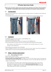
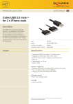
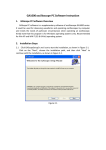
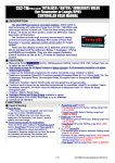
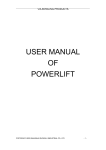
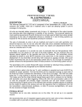
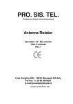
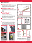
VIA BOWLING FASTTRACK
File No.: M200506-01
COPYRIGHT 2005, VIA BOWLING PRODUCTS
MC2 BOWLING FASTTRACK INSTALLATION & SERVICE MANUAL
I. General Description
1. The fasttrack ball return system is to send the ball
back to the Blower where the player pick up the ball.
2. The fasttrack ball return system is composed of such
components as fasttrack frame (Dolly), fasttrack motor,
fast pulley assembly and adjust lever, ball sense
assembly and track. (See fig. 1)
Pin
Frame
Adjust Lever
Motor
Fast Pulley Assy.
Ball sense Assy.
Track
Fig. 1
COPYRIGHT ©2004, SHANGHAI ZHONGLU INDUSTIAL CO., LTD
1 OF 12
MC2 BOWLING FASTTRACK INSTALLATION & SERVICE MANUAL
3. Operating principle of the ball return system:
The ball rolls into Fastrack via the Ball Door.
Directed by the ball-guided tray and Lock Assemble
triged, it passes through the two disjunctors of the ballholding baffle plate and comes into the track. And the
ball accelerated by Flat Belt, then it flies to the Blower
along the track.
II. Technical Parameter
Power of the Fasttrack motor:550W+60W
Length×Width×Height:1145×250×1100 mm
III. Adjustment of the Ball Return System
Note: It is usually adjusted before leaving factory and
does not need re-adjustment.
1. Adjustment of the Flat Belt (See fig. 2)
Any disalignment of the two axles of the fast pulley assembly
will lead to the deviation of the Flat Belt. Therefore, regulate
the two adjustment bolts of fast belt pulley on the traction
wheel axle to solve the deviation problem.
Turn the primary wheel manually and observe the running of
the Flat Belt, whenever the flat belt slides, loosen the nut on
the deviated side and regulate the adjustment bolts clockwise
to correct the displacement of Flat Belt and make it align
with the center of the wheel. Alternatively, loosen the nut on
the deviated side of the flat belt and regulate the adjustment
bolt counterclockwise to correct the deviation.
2. Adjustment of Limited Cam and Pressing Force
(See fig. 2)
a. Adjustment of limited cam: Loose the four binding
bolts of limited cam and regulate the Adjustment Bolt
1 of the cam, to make the distance between the fast
COPYRIGHT ©2004, SHANGHAI ZHONGLU INDUSTIAL CO., LTD
2 OF 12
MC2 BOWLING FASTTRACK INSTALLATION & SERVICE MANUAL
Adjust Bolt 2
Spring
Limited Cam
Bolt
Adjust Bolt 1
Grease Cock
Pulley
Adjust Bolt
Flat Belt
Fig. 2
pulley and bottom of the fasttrack frame be about 220mm.
Then fasten the binding bolts.
b. Adjustment of pressing force: Loosen the pressure
regulating screw nuts of the wheel rim, and regulate the
adjustment bolt 2 clockwise or counterclockwise to make
the spring reach a length of 105mm.
3. Adjustment
of
Ball-holding
Components (See fig.3)
Baffle
Plate
Adjustment of ball-holding baffle plate components:
Switch 1 and switch 2 are the key of the Lock Assembly,
COPYRIGHT ©2004, SHANGHAI ZHONGLU INDUSTIAL CO., LTD
3 OF 12
MC2 BOWLING FASTTRACK INSTALLATION & SERVICE MANUAL
which determines whether the ball can enter the track
smoothly. Therefore, it is important to adjust the height
of switches appropriately.
Switch 1
Pan
Switch 2
Set Pin
Lock Arm
Trigger
Spring
Set Bolt
Fig. 3
a. The Lock Assembly will not open unless both switch 1
and 2 are pressed down at the same time. Either one of
them will not open the Lock Assembly.
b. When the Lock Assemble opens while only switch 1 is
pressed down, it should be adjusted. Loose lock-nut of
Switch 1, adjust switch and make the ball enter smoothly
and can press down it, then the Set Pin should not
separate from the Lock Arm with a joggling distance of
2-3mm.
COPYRIGHT ©2004, SHANGHAI ZHONGLU INDUSTIAL CO., LTD
4 OF 12
MC2 BOWLING FASTTRACK INSTALLATION & SERVICE MANUAL
c. When the ball pan opens while only switch 2 is pressed
down, the distance between the Set Bolt and the Lock
Arm should be adjusted. Loosen the nuts on the Set Bolt
to reduce the distance (changed into about 0.5mm) or
regulate the trigger to increase its distance with the Lock
Arm so as to ensure the one between the Limited Bolt
and Lock Arm.
d. After the switch 1 and 2 are adjusted respectively, fasten
all the nuts and test with a ball. (Suggestion: put a 16 lb. ball
onto the ball pan and let it roll down naturally. When the
Lock Assembly opened; and Pan comes down and restores
smoothly, the adjustment is over. When the ball pan opens
but can hardly restores, Set bolt should be adjusted backward
so that the interspace is enlarged a little. (Or expand the
spring a little). If the Lock Assembly does not open, make readjustment according to step b and c.
4. Adjustment of Rudder and Ball Sense and Paddle
Assembly
a. Operation of ball sense assembly:
Adjust the height of cam follower bearing, make it can
reach the Rudder Cam, and high enough to reach the Cam.
The cam follower bearing can be adjusted with inserting
spacers. (See fig. 4)
b. Adjustment of Rudder Bracket Shaft (See fig. 4 & 5)
z The Rudder Bracket are mounted at the position near the
center of both frames of Fasttrack, and with a 15mm
deviation close to the left frame.
z Loosen the bolts to adjust.
z Remove the spring from the Belt Tighten and remove the
belt from the Crank Pulley.
COPYRIGHT ©2004, SHANGHAI ZHONGLU INDUSTIAL CO., LTD
5 OF 12
MC2 BOWLING FASTTRACK INSTALLATION & SERVICE MANUAL
Cam Weldment
Trip Arm
Link
Eccentric Plate
Cam Follower
Spacer
Rudder Cam
Cam
Fig. 4
Insert Spacer to adjust
the Paddle Arm
Rudder Bracket
Frame
Fig. 5
COPYRIGHT ©2004, SHANGHAI ZHONGLU INDUSTIAL CO., LTD
6 OF 12
MC2 BOWLING FASTTRACK INSTALLATION & SERVICE MANUAL
c. Adjustment of Rudder and Ball Sense
1. Remove the two Trip Arms.
2. Remove the nuts from the eccentric axis. (See fig. 6)
3. Pull out and turn away the link from the eccentric axis.
4. Loose the Nuts of adjustment axis, and clockwise revolve
the adjustment plate to the biggest degree, then fasten all
nuts.
Eccentric
Lock
Pulley
Nut
Link
Nut
R.H. Trip Cam
L.H. Trip Cam
Assembly
Nut
Adjustment Plate
Eccentric
Axis
Paddle Arm
Fig.6
COPYRIGHT ©2004, SHANGHAI ZHONGLU INDUSTIAL CO., LTD
7 OF 12
MC2 BOWLING FASTTRACK INSTALLATION & SERVICE MANUAL
d. Adjustment of Paddle Arm Assembly
1. Run the Rudder, make sure the paddle Arm can touch the
both frames of Fasttrack, the Paddle Arm should move
smoothly.
2. If the rod does not move smoothly, insert some spacer
between the Bracket and Frame to adjust the Paddle Arm.
(See Fig. 5)
e. Adjustment of Rudder and Ball Sense by Regulating the
Link
1. Fix one end of the link onto the eccentric axis (See fig. 6),
and revolve the rudder driving pulley (eccentric belt pulley
wheel) while observing the movement of the rod assembly
(ball sense rod).
2. Adjust the length of the link to have the rod assembly (ball
sense rod) swing on the basis of the central line
symmetrically. Then fix the fastening nuts. (See fig. 6)
While adjusting the links, extend the left one to increase the
distance and shorten the right one to decrease the distance.
Since both ends of the rod are with right hand screw thread,
one end should be removed to adjust the other.
3. Loosen the fastening nuts on the adjustment plate, and
move the plate counterclockwise to make the rod assembly
contact both sides of the bracket with balanced force instead
of towing the cam weldment. Then fasten the nuts.
4. Recheck the machine by turning the crank pulley
(eccentric pulley wheel). If the rod assembly (ball sense rod)
only contact one side of the bracket, re-adjust according to
the Step 2.
f. Adjustment of Cam Weldment
COPYRIGHT ©2004, SHANGHAI ZHONGLU INDUSTIAL CO., LTD
8 OF 12
MC2 BOWLING FASTTRACK INSTALLATION & SERVICE MANUAL
1. Turn the crank pulley to make the rod assembly (ball sense
rod) be situated in the oscillation center of the bracket plate.
(See fig. 6)
2. Push the cam weldment follower of the cam weldment
forward as much as possible.
3. There should be a gap of 3mm between the cam weldment
and the cam weldment on both sides.
4. If adjustment is necessary, loosen the bolts of the bent
lever and relocate the lever.
5. Then fasten the bolts and re-check whether the gaps on
both sides accord with the requirements.
g. Adjustment of Trip Arm (See fig. 6)
1.Revolve the crank pulley to turn the rod assembly (ball
sense rod) to the margin of its running distance so that the
pulley can slightly contact the left bracket. The contacting
position should be fixed.
2. Fix the left trip arm (baffle plate) to have the surface of the
elbow of the arm contact the cam weldment. Then fasten the
bolts.
3. Adjust the right trip arm (baffle plate) by repeating Step 1
& 2.
h. Inspection of Trip Arm
a) Revolve the crank pulley manually.
b) When the ball sense swings back and forth, push the
cam weldment towards the rear side of the machine.
COPYRIGHT ©2004, SHANGHAI ZHONGLU INDUSTIAL CO., LTD
9 OF 12
MC2 BOWLING FASTTRACK INSTALLATION & SERVICE MANUAL
c) When the cam weldment follower hits the trip arm,
have the follower restore its position which heads to
the front of the machine.
d) Push forward the cam weldment follower and check
whether it restores to position towards the frond side.
If it does, the adjustment is successful. Check the
other side of the follower with the same method.
e) Fix the triangle belt onto the crank pulley and the
spring onto the belt tightening pulley.
f) Re-check the operation of the cam weldment follower
by touching it with screwdriver or wooden batten. If
the follower does not restore to its position correctly
towards the front, readjust the trip arm.
IV. Installation of Ball Return System (See fig. 7)
1. Place the spirit level, in turn, on the top and at each side of
the dolly. Regulate the adjustment bolts of the rollers, left,
right, front or back, to keep the dolly in horizontal position.
2. Adjust the height of the dolly so that the center of its
entrance hole is slightly lower than the one of its return hole.
Due to the flatness of the ground and the installing deviation
of ball lane, adjust accordingly so that the upper side of the
fasttrack frame is 33-37mm away from the top of the dolly.
3. After adjusting the height, fasten all the nuts.
4. The horizontal space should be based on the requiement
that the four pins on the rear side of the dolly can be inserted
into the corresponding holes of the fasttrack frame.
COPYRIGHT ©2004, SHANGHAI ZHONGLU INDUSTIAL CO., LTD
10 OF 12
MC2 BOWLING FASTTRACK INSTALLATION & SERVICE MANUAL
Fasttrack
Rear Roller
Front Roller
Iron Kick Back
Pin
Fig. 7
V. Maintenance of Ball Return System
1. The ball return system needs maintenance after running for
500 hours.
2. Shut down the power supply and pull out the Fasttrack,
clean up all omponents.
COPYRIGHT ©2004, SHANGHAI ZHONGLU INDUSTIAL CO., LTD
11 OF 12
MC2 BOWLING FASTTRACK INSTALLATION & SERVICE MANUAL
3. Check whether the components are worn out or damaged,
replace them if necessary.
4. Check all of the fasteners, fastening the loosened bolts and
nuts.
5. Inject grease in the grease cock and lubricate all the
moving components with the engine oil, which should be
innocuous and with effective lubricating property.
6. Replace the capacitor of the motor (60W) after running
3000 hours.
VI. Trouble shoot
Problems
The ball
return
system
does not
run.
The ball
does not
enter the
track.
Possible causes
The power cord is not
connected correctly;
The small disjunctor is not
closed.
The connecting wire is not
linked with the pindepositing machine.
The ball-holding baffle plate
does not open.
The amplitude of swing of
the ball sense plate is not
enough.
COPYRIGHT ©2004, SHANGHAI ZHONGLU INDUSTIAL CO., LTD
Solutions
Connect the power
cord correctly;
Close the small
disjunctor to the
ON position;
Connect all the
wires well.
Adjust the ballholding
baffle
plate.
Adjust the ball
sense system.
12 OF 12