1
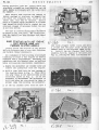
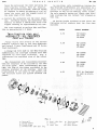
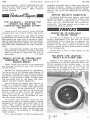
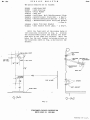
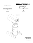
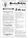
Hr. H. J. Symon
5 T U DEB A K E R - PAC
K A R D COR
General Service Department
Stud~bakar-Packard Corporation
P 0 R A'T ION
J U N E
NO.325
1 957
SOUTH
STATION WAGON TAIL GATE RATTLE STUDEBAKER and PACKARD CLIPPER
MODELS
Please record this article on the Service
Bulletin reference page of your 1957 Studebaker
and Packard Clipper Supplements.
Rattles at the station wagon tail gates are
often a result of the gate or gates being loose
within
the opening.
This condition
can be
eliminated
by installation
of shims under the
tail gate bumper blocks.
The shim, Part No.
1314621 is 1/16- thick and a sufficient number
of shims should
be installed
so that in a
closed position,
the tail gate contacts the
bumpers.
When installing the shims, distribute
the shims at both sides as required to maintain
the proper alignment
of the gate within the
opening.
In some instances,
it may be necessary
to
cut out the center portion of the shim if there
is interference
between the edge of the shim
and the bumper block retaining screws.
To properly check the lubricant level and to
prevent
overfilling
of the unit, check the
level by removing one of the lower top cover
retaining screws.
The oil level should be at
the edge of the screw hole.
Filling the unit
to the level of the filler
hole, although
causing no harm to the unit, may result in a
lubricant leak at the jacket immediately above
t he housing.
VALVE SPRING RETAINERS - 55th
and 56th'SERIES PACKARD and
1956 STUDEBAKER GOLDEN HAWK
ENGINES
G 0
0
D
record
SERVICE
this articLe
----
INDIANA
STUDEBAKER and PACKARD CLIPPER
Hard Starting
with Hot Engine - 1957
Golden Hawk and packard Clipper
Models.
Rear Shock Absorber
Noise - 1957
Studebaker
and packard Clipper
Models
Station Wagon Tail Gate Rattle Studebaker
and packard CI ipper Mode Is
Steering
Gear Lubricant
Level - 576,
51H, and 57L Models.
• • • • • • ••
Twin-Traction
Rear Axle Assemblies
- All
Passenger
Cars and Trucks.
• • • •
Valve Spring Retainers
- 55th and 56th
Series packard and 1956 Golden Hawk
Models •••••••••••••••••
2
It
1
1
}
1
STUDEBAKER
Bumper Bar Distortion
- 1957 Studebaker
Models.
• • • • • ••
•••••
Right Rear Fender Rumble - Scotsman
Models.
Steering
Wheel Shake - 57B and 57H
Models.
• •
•
It
•
It
•
It
cu PPER
5
5
5
TRUCKS
Correction
to Supplemen~
- }E Series
Trucks.
• • • • • • • • • • • • •
New Location of Spare Tire - Models
Equipped
with pickup Body.
• • •
5
5
Bul le t i n.reference page at the end of the Engine
- Sky Power 352 section of your 1956 Studebaker
passenger car Shop ManuaL and on the Kates page
of your 1955-56 packard Shop ManuaL.
Valve Spring Retainer, part NO. 6492077 has
been released for use on both intake and exhaust
valves of all 55th and 56th Series Packard and
1956 Studebaker
Golden Hawk engines.
Valve
on the Service
CREATES·
27,
Erratic
Action of Torsion-Level
Suspension
- 55th and 56th Series packard
Models •••••••••••••••
Service
Bulletin
correction
- 1951
Packard CI ipper Time Guide.
• • ••
Time Atlowance
- Steering
Post Bracket
and Brace Instal1at ion - Packard
Clipper
Models •••••••••••••
Please record this article on the Service
Bulletin reference page of your 1957 Studebaker
and Packard CLipper SuppLements.
prease
BEND
page
PAC KARD
STEERING GEAR LUBRICANT LEVEL
57B, 57H, and 57l MODELS
WITH STANDARD STEERING
SS
----
CUSTOMER
GOO
D
w
L L
S E R V ICE
No. 325
B U l lET
1H
June
Spring
Re.tainer, Part NO. 440511 which was
originally released has been cancelled and the
Parts Depots will supply only the latest part
NO. 6492077.
When service work requires
the removal of
valves, springs, or retainers, we suggest that
you check the retainers
and, if not of the
latest type, that they be replaced.
service
stock of stripped engine assemblies or cyl1nd.er
head assemblies should also be checked and the
retainers changed if necessary before the unit
is put into service.
The type of retainer can be readily determined
by means of the file test.
The latest type,
part No. 6492077 has been hardened and cannot
be filed.
HARD STARTING WITH HOT ENGINE
- 1957 GOLDEN HAWK and
PACKARD CLIPPER MODELS
pLease record this article on the Service
Bulletin Reference page of your 1957 Studebaker
and Packard Clipper Supplements.
on a complaint of hard starting or prolonged
cranking
to start a hot engine
on models
equipped
with a sup er c na r ge r , modifying
the
carburetor
and air chamber cpver as outlined
below will provide considerable
improvement.
1. Remove
remove
vent val ve (flapper valve) locate and drill
a 1- hole and two 5/32" holes in the air
chamber cover at the locations shown in Fig.
3.
Install
the Air Chamber
Vent Valve _
Assembly, Part NO. 1542765 in the cover (see
Fig. 4), placing two small flat washers be-
the carburetor air chamber cover and
the carburetor
from the engine.
2. Drill a 7/64- hole i~to the vent passage at
the location shown in Fig. 1. Then, dri Ll
two 5/64" holes in the throttle body at the
locations
shown
in Fig. 2.
It is not
necessary to disassemble
the carburetor
to
drill the holes but care should be taken to
prevent chips from entering the carburetor.
3. If the air chamber
cover
Fig. 1
does
not
have
a
Fig. 4
B U l LET
S E R V ICE
June
tween the spring and the cover and. using two
self-tapping
screws,
Part NO. G453113.
After the valve is installed, bend the spring
as required to obtain an opening of 1/4" between the cover and the highest point at
the outer edge of the valve.
"0. 325
IH
As you know, axle assemblies
having
the
Twin-Traction
differential
are identified
by a
Le t te r ••T" s tam p e don
a bra s s tag w h i chi s
attached
to one of the housing cover screws.
The axle assembly having the latest type disctype c Iu t c hes has the letters' 'TO" s tamped on
this tag.
4. Install
the carburetor and the cover assembly.
carefully
adjust the carburetor
idle
mixture to obtain a smooth idle with a hot
engine running
at approximately
575 rpm.
The time required
tion is approximately
3E Series trucks produced
on and after the
following
serial numbers
have the disc-type
clutches:
to perform this modifica1.2 hours.
RATIO
TW1N-TRACTION REAR AXLE
ASSEMBLI ES - ALL PASSENGER
CARS and TRUCKS
PLease record this articLe on the Service
Bunetin
reference page Of your 1957 Sbude ba ker
and Packard CLipper SuppLements and 3E Series
Truck SuppLement.
A change has been made in the Twin-Traction
differential;
the cone-type clutches have been
replaced
by disc-type
clutches.
Fig. 5
illustrates
the exploded
view of the latest
type.
The disassembly
and reassembly
procedure
with the exception of the clutches is the same
for both types.
When reassembling
the disc
type, the lugs of the plates are placed 1n the
notches
provided
in the housing.
Note the
relationship
of the discs to the plates; the
two frictidn
discs are placed
between
the
plates.
SERIAL
NUMBERS
3.73
E5-124101
E6-16084
E7-8689
4.09
E5-124276
E6-16188
E7-8841
4.27
E5-124386
E6-16281
E7-8958
4.89
E5-124590
E6-16396
E7-9103
4.55
Will be furnished
as soon as available.
- :~
Fig. 5
1. Case Ha If
2. Clutch
plates
3. Clutch Discs
~. Differential
5. Bevel Side
6. pinions
7.
Side
GeAr
cross
pins
Ge
ar
8. Thrust
Block
9. Case Half
10. Case Screws
Ring
3
"0.
S E R V ICE
325
REAR SHOCK ABSORBER NOISE 1957, STUDEBAKER AND PACKARD
CLIPPER MODELS
Please record this article on the Service
Bulletin reference page of your 1957 Studebaker
and Packard Clipper Supplements.
LoW speed rear shock absorber noise or rattle
can be corrected
by the replacement
of the
mounting bushings and sleeves.
They have been
released for service under the following part
numbers:
419932
1544479
1544480
Bushing
Bushing Sleeve
BUS hing Sleeve
- Lower
- uppe r
Although in some instances new bushings may
not eliminate
the condition
completely,
they
will usually reduce the noise to an acceptable
level.
To remove the bushings,
remove the shock
absorber and simply press out the old bushing
and sleeve.
To install,
first,
press
in the new bushing
and
then the sleeve.
At the lower
mounting,
make sure the shock
absorber
mounting
eye is offset
on the sleeve
as shown in Fig.
6. Shock absorber with a gravel
shield
must be installed
with
the shield
toward'the
front
oft h e car.
Th ere for e. t his
must
be considered
when
installing
the sleeve
so that it
is offset in the right directio~
to be properly
positioned
when
ins tall ed.
Fig. 6
O-C1~
NS.ii9
STEERING WHEEL SHAKE - 57B
and 57H SEDAN MODELS
Please record this article on the Service
Bulletin reference page Of your 1957 Studebaker
SuPP lemen t.
If a condition
of steering wheel shake is
encountered
in a 57B or 57H model, it can be
corrected
by the installation
of additional
brace rods and change in mounting of the steering column at the instrument board in the same
manner as outlined
for the packard
Clipper
models in service Bulletin NO. 324.
The time required' for the modlf Ic a t Lo n was
not included in ~ulletin No. 324. The operation
BULLETIN
June
number
assigned
and
the time
allowance
are:
S42 - Steering Post Bracket and Grace Rods
Installation
(includes
aligning
steering
wheel to center
of high spot and toe-in
adjustment)
2.5 hours
please note this operation
in the Steering
secti~n
of your 1957 Studebaker
Time Guide.
BUMPER BAR DISTORTION - 1057
STUDEBAKER MODELS
Please record this articLe on the Service
Bulletin reference page of your 1957 Studebaker
Supplement.
New type spacers,
Part NO. 311446X2
have
been released for installation
between the inner
surface of the bumper face bar and the support
brackets to prevent distortion
of the bar When
the attaching bolts are tightened.
Distortion
of the bar has in some cases caused cracking of
the plating and resulted in rusting in the area
around the attaching bolts.
Therefore,
any time the bumper face bar is
replaced, the new type spacers should be installed. Four spacers are used at the front bumper
and three at the rear bumper.
The new type spacers
spacer, part NO. 1541769
used.
eliminate
the use of
which was previously
RIGHT REAR FENDER RUMBLE
SCOTStv1ANMODELS
Please record this article on the Service
Bulletin reference page of your 1957 StUdebaker
Supplement.
on complaints of the right rear fender oilcanning or rumbling on Scotsman models, install
a brace between the fender and the wheel housing
panel.
This brace entered
production
with
Seria~No.
G-1396759.
The brace is fastened to a weld bolt which is
located abOve and slightly
to the rear of the
wheel.
This bol t is part of the assembly
in
production and is used for the same purpose on
other models.
Therefore,
it is necessary only
to procure the brace and the attaching nut and
washers.
The part numbers are:
1320017-P
G446363
- Brace
- Plain Washer
G120214
Gl20376
- Lock washer
- Nut
To install the brace, slip the end with the
elongated hole over the weld bolt. then, install
June
SERVICE
the nut and washers.
Before tightening the nut,
push the brace outward so that the end bears
firmly against
the fender.
Then, tighten
the nut securely.
BULLETIN
No. 375
Assembly retaining nuts to make sure they are
properly
torqued.
Torque to specifications
outlined in the 1955-56 packard Service Manual,
page 18, Fig. 53 of the Suspension and Steering
section.
SERVICE BULLETIN CORRECTION
TIME ALLOwANCE - STEERING POST
BRACKET AND BRACE ROD
INSTALLATION - PACKARD CLIPPER
MODELS
Ptea,se record this article
in the Steering
section of your 1957 Packard Clipper Time Guide.
In Service Bulletin NO. 324 (May) we issued
instructions for installation of the steering
post bracket and brace rods to correct a condition of steering wheel shake in the 57L models.
The following operation number and time allowancehave
been established for thisinstallation:
S42 - Steering Post Bracket and Brace Rods
Installation
(includes
aligning steering
wheel to center of high spot and toe-in
adj us tmen t)
2.5 hours
ERRATIC ACTION OF TORSION-LEVEL
SUSPENSION- 55th and 56th
PACKARD MODELS
Pt,ease record this
and Steering
section
Service Nanua t.
article
in the Suspension
oj your 1955-56 Packard
Because the control switch is responsible
for the action of the Torsion-Level system, it
is natural to assume that any erratic action of
the system is caused by a faulty control switch.
However, it can also be a result of loose bushing retai~ing
nuts at the upper and low~r
support arm inner brack~t assemblies.
In Service Bulletin *323 (April) under Time
Allowance changes - 1957 packard Clipper Time
Guide, the time for Operation RlOO - Radiator
Cote, R & R or install
new was stated
incorrectly.
The time should be 0.9 hours instead of 1.9 hours as printed.
TRUCKS
CORRECTION TO SUPPLEMENT
3E SERIES TRUCKS
on page 23 in Figure 31 of the 3E Series
Trucks
Supplement
the 2nd and 3rd speed
synchronizer
sleevi (Item 24) is shown in the
wrong position.
In its correct position" the
shoulder at the inner diameter of the sleeve
would be toward the main drive pinion or front
of the transmission.
Please make
illustration.
a note
to this effect
on the
NEW SPARE TIRE LOCATION
MODELS WITH PICKUP BODY
Recently a new location for the spare tire
was released as a factory installed option for
trucks equipped with a piCkup body.
At the
optional location, the tire is mounted at the
front wall of the body (see Fig. '7). This can
very readily be adapted to prior models for
owners desiring this "in the box" location.
The action may be normal when the car is
driven on a relatively smooth road. But, over
a rough road, after a severe brake application
or quick release of the accelerator,
it will
move up or down to the limit of its travel and
will not return to level or will take considerable time to return.
It may also "hunt" in
seeking the level so that it continues to override the normal level position.
To correct
the condition,
first set the
Torsion-Level system at normal height; without
passengers and not more than normal load in the
trunk.
Then, tighten the nut at each end of
the inner bracket of the upper and lower support
arms at both sides to make certain that the
inner sleeve of each bushing is bottomed and
locked secure 1y.
It is also advisable to check the Compensator
9
Fig. 7
J
ObI
5
S E R V ICE
No. 325
The parts
293805
293807
41X557G
G144235
1654669
G180075
G120376
G120638
1554668
G144811
required
June
BULLETIN
are
as
follows:
Hal d-uovn
nor t
Hold-down
Lug
plain
Washer
Wing Nut
Hold-down
Bolt
Reinforcement
Reinforcement
Plate
Bolt
- 2
Reinforcement
Plate
Bolt Nut - 2
Reinforcement
Plate
Bolt Lock
- 2
- Spare
Tire
Rest Bracket
- Rest Bracket
Screw
(#10)
- 2
-
Plate
Req d ,
Req'd.
Washer
Req'd.
r
Req'd.
Drill
the front
wall of the pickup
body at
the locations
indicated
in Fig.
8.
Install
the reinforcement
plate
and install
the holddown bolt
in the lower
set of holes.
Drill
two
holes
for the rest
bracket
retaining
screws
at
the locations
shown in Fig.
8 and install
the
bracket.
I
i __
L
__
~
_,
.!'~
D/~-:HILL:< HOLES
I
DHILL •.~
DIA. HOLE
I
f/4lli_/~
I
"-A
I DRILL
•
I
DIA. HOLE
1/4t/~61
REINFORCEMENT
PLATE:
I
I
WING
SIDE
of BODY
SCREWS
REST
/
NUT
BRACKET
FLOOR of BODY
q- olo3
Fig.
8
STUDEBAKER-PACKARD CORPORATION
SOUTH BEND 27. INDIANA
PRINTEO
IN U.S.A.