1
1/3" CCD BLACK & WHITE CAMERA
1/3 Zoll CCD SCHWARZWEISSKAMERA
CAMERA NOIR ET BLANC CCD 1/3"
TELECAMERA CCD IN BIANCO E NERO DA 1/3"
INSTRUCTION
MANUAL
Worldwide Support Center
1301 Waters Ridge Drive • Lewisville, TX 75057
(800) 796-2288• (972) 353-6400• FAX (972) 353-6670
Ultrak - Groupe Bisset
98 Ter, Boulevard Héloïse l F-95103 Argenteuil Cedex l France
(33) 0134/234747 l FAX (33) 0134/234745
Ultrak - Intervision
l
l
445 Oakshott Place, Walton Summit Bamber Bridge, Preston , PR5 8AT
Lancashire, England
l
(44) 01772/515999 FAX (44) 01772/513333
Ultrak - Casarotto Security
Via Treviso, 2/4 l 31020 San Vendemiano (Treviso) Italy
(39) 0438/410245 l FAX (39) 0438/370471
Ultrak - VideV GmbH
Großenbaumer Weg 10 l D-40472 Düsseldorf Germany
(49) 0211/41509-0 l FAX (49) 0211/424019
Please read this manual thoroughly before use, and keep it handy for future reference.
ISSUE 1 November 1998
AUSGABE 1 November 1998
ÉDITION 1 Novembre 1998
EDIZIONE 1 Novembre 1998
1998 BY ULTRAK
ALL RIGHTS RESERVED
PRINTED IN KOREA
ALLE RECHTE VORBEHALTEN
GEDRUCKT IN KOREA
TOUS DROITS RESERVES
IMPRIME IN COREE
TUTTI I DIRITTI RISERVATI
STAMPATO IN COREA
ULTRAK
1301 WATERS RIDGE DRIVE
LEWISVILLE, TEXAS 75057
ALL RIGHTS RESERVED. NO PART OF THIS PUBLICATION MAY BE REPRODUCED
BY ANY MEANS WITHOUT WRITTEN PERMISSION FROM ULTRAK.
THE INFORMATION IN THIS PUBLICATION IS BELIEVED TO BE ACCURATE IN ALL
RESPECTS. HOWEVER, ULTRAK CANNOT ASSUME RESPONSIBILITY FOR ANY
CONSEQUENCES RESULTING FROM THE USE THEREOF. THE INFORMATION
CONTAINED HEREIN IS SUBJECT TO CHANGE WITHOUT NOTICE. REVISIONS OR
NEW EDITIONS TO THIS PUBLICATION MAY BE ISSUED TO INCORPORATE SUCH
CHANGES.
ALLE RECHTE VORBEHALTEN. KEIN TEIL DIESER VERÖFFENTLICHUNG DARF OHNE SCHRIFTLICHE
ZUSTIMMUNG SEITENS ULTRAK VERÖFFENTLICHT, VERVIELFÄLTIGT ODER AN DRITTE
WEITERGEGEBEN WERDEN.
DIE INFORMATION IN DIESER VERÖFFENTLICHUNG WURDE NACH BESTERN WISSEN UND
GEWISSEN ERSTELLT. ULTRAK LEHNT JEDWEDE REGRESSANFORDERUNGEN FÜR EVENTUELLE
ENSTEHENDE FOLGEN AUS DER NUTZUNG DIESER INFORMATION AB. Ä
NDERUNGEN VORBEHALTEN. NEUE ODER ÜBERARBEITETE AUSGABEN KÖNNEN SOLCHE
ÄNDERUNGEN BEINHALTEN.
TOUS DROITS RESERVES. AUCUNE PARTIE DE CETTE PUBLICATION NE PEUT ÊTRE REPRODUITE
PAR QUELQUE MOYEN QUE CE SOIT SANS ACCORD ECRIT DE ULTRAK.Ê
LES INFORMATIONS SONT REPUTEES VRAIES. TOUTEFOIS,UTRAK NE PEUT PAS ÊTRE TENU
RESPONSABLE DE TOUTES CONSÉQUENCES RÉSULTANT DE LEUR UTILISATION. LES
INFORMATIONS CONTENUES SONT SUJETS À CHANGEMENT SANS PRÉAVIS. DES RÉ
VISIONS OU NOUVELLES ÉDITIONS DE CETTE PUBLICATION PEUVENT ÊTRE FAITES POUR
INCORPORER CES CHANGEMENTS.
TUTTI I DIRITTI RISERVATI. NESSUNA PARTE DI QUESTA PUBBLICAZIONE PUO' ESSERE RIPRODOTTA
PER NESSUNO SCOPO SENZA AUTORIZZAZIONESCRITTA DELLA ULTRAK.
SI PRESUME CHE LE INFORMAZIONI CONTENUTE IN QUESTA PUBBLICAZIONE SIANO ACCURATE E
CORRETTE. COMUNQUE, ULTRAK NON SI ASSUME NESSUNA RESPONSABILITA' PER LE
CONSEGUENZE DERIVANTI DALL'USO DI QUESTO MANUALE. LE INFORMAZIONI DI SEGUITO
RIPORTATE SONO SOGGETTE A CAMBIAMENTI SENZA PREAVVISO. REVISIONI O NUOVE EDIZIONI DI
QUESTA PUBBLICAZIONE POSSONO ESSERE RILASCIATE PER INCORPORARE QUESTI
2
WARNING:
TO REDUCE THE RISKOFFIREOR ELECTRIC SHOCK, DO NOT EXPOSE THIS PRODUCT
TO RAIN OR MOISTURE.DO NOT INSERT ANY METALLIC OBJECT THROUGH VENTILATION
GRILLS.
CAUTION:
Explanation of Graphical Symbols
The lightning flash with arrowhead symbol, within an equilateral triangle, is intended to
alert the user to the presence of uninsulated "dangerous voltage" within the
product'senclosure that may be of sufficient magnitude to constitute a risk of electric
shock to persons.
The exclamation point within an equilateral triangle is intended to alert the user to the
presence of important operating and maintenance (servicing) instructions in the literature
accompanying the product.
CE COMPLIANCE STATEMENT
WARNING
This is a Class A product. In a domestic environment this product may cause radio
interference in which case the user may be required to take adequate measures.
3
IMPORTANT SAFEGUARDS
1. READ INSTRUCTIONS -- All the safety and operating
instructions should be readbeforetheapplianceis operated.
2. RETAIN INSTRUCTIONS -- The safety and operating
instructions should be retainedforfuturereference.
3. CLEANING -- Unplug video equipment from the power
source beforecleaning. Do not use liquidcleaners or aerosol
cleaners. Use a damp cloth for cleaning.
4. ATTACHMENTS -- Do not use attachments not
recommended by the video equipment manufacturer as they
may result in the risk of fire, electric shock or injury to
persons.
5. WATER AND MOISTURE -- Do not use video equipment
near water -- for example, near a bathtub, washbowl, kitchen
sink, laundry tub, in a wet basement, or near a swimming
pool, orthelike.
6. ACCESSORIES -- Do not place video equipment on an
unstable cart, stand or table. The video equipment may fall,
causing serious injury to a childoradult, and serious damage
to the equipment. Wall or shelf mounting should follow the
manufacturer's instructions, and should use a mounting kit
approved by the manufacturer.
6A. Video equipment and cart
combinations should bemovedwith
care. Quick stops,excessive force,
andunevensurfaces may causethe
equipment and cart combination tooverturn.
7. VENTILATION -- Slots and openings in the cabinet and the
back or bottom are provided for ventilation, and to ensure
reliable operation of the video equipment and to protect it
from overheating. These openings must not be blocked or
covered. The openings should never be blocked by placing
the video equipment on a bed, sofa, rug, or other similar
surface. Video equipment should never be placed near or
over a radiator or heat register. Video equipment should not
be placed in a built-in installation such as a bookcase unless
proper ventilation is provided.
8. POWER SOURCES -- Video equipment should be operated
only from the type of power source indicated on the marking
label. If you are not sure of the type of power supplied to your
home, consult your video equipment dealer or local power
company. For video equipment designed to operate from
batterypowerrefer to the operating instructions.
9. POWER CORDS -- Do not allow anything to rest on the
power cord. Do not locate video equipment where the cord
willbeabusedbypersonswalkingonit.
10. HEED WARNINGS -- Follow all instructions marked on the
video equipment.
4
11. LIGHTNING -- For added protection for video equipment
during a lightning storm, or when it is left unattended and
unused for long periods of time, unplug it from the wall outlet
and disconnect the antenna or cable system. This will
prevent damage to the video product due to lightning and
power-line surges.
12. OVERLOADING --Do not overload wall outlets and
extension cords as this can result in a risk of fire or electric
shock.
13. OBJECT AND LIQUID ENTRY -- Never push objects of any
kind into video equipment through openings as they may
touch dangerous voltage points or short-out parts that could
result in a fire or electric shock. Never spill liquid of any kind
on theproduct.
14. SERVICING -- Do not attempt to service video equipment
yourself as opening or removing covers may expose you to
dangerous voltage or other hazards. Refer all servicing to
qualified servicepersonnel.
15. DAMAGE REQUIRING SERVICE -- Unplug video
equipmentfromthewalloutletandreferservicing to qualified
servicepersonnelunderthefollowingconditions:
A. When the power-supply cord or the plug has been
damaged.
B. If liquid has spilled, or objects have fallen into the video
product.
C.Ifthevideoproducthasbeenexposed to rain or water.
D. If the video product does not operate normally by
following the operating instructions, adjust only those
controls that are covered by the operating instructions as an
improper adjustment of other controls may result in damage
and willoften requireextensive work byaqualifiedtechnician
to restore the videoproduct to its normaloperation.
E. If the video product has been dropped, or the cabinet
damaged.
F. When the video product exhibits a distinct change in
performance --thisindicatesaneedforservice.
16. REPLACEMENT PARTS -- When replacement parts are
required, be sure the service technician has used
replacement parts specified by themanufacturer or that have
the same characteristics as the original part. Unauthorized
substitutions may result in fire, electric shock or other
hazards.
17. SAFETY CHECK -- Upon completion of any service or
repairs to this video product, ask the service technician to
perform safety checks to determine that the video product is
inproperoperatingcondition.
18. FIELD INSTALLATION --Thisinstallation shouldbemadeby
a qualified service person and should conform to all local
codes.
TABLE OF CONTENTS
1 PURPOSE
6
2 INSTALLATION PRECAUTIONS
6
3 SYSTEM INSTALLATION
7
4 MAJOR OPERATION CONTROLS AND THEIR FUNCTION
4.1 C/CS, Back Focus Adjust Ring
4.2 Back Focus Lock Screw
4.3 Auto Iris Connector
4.4 Mounting Bracket Hole
4.5 Functions
4.6 Video Output Connector
4.7 Power Input Terminal
4.8 Power LED
9
5 LENS ADJUSTMENT
5.1 Manual Iris Lens
5.2 Video-type Auto Iris Lens
5.3 DC-type Auto Iris Lens
5.4 Back Focus Adjustment
5.5 Zoom Lens Back Focus Adjustment
13
6 TROUBLE SHOOTING
18
7 MAINTENANCE
18
8 SPECIFICATIONS
8.1 Standard Resolution
8.2 High Resolution
19
5
INHALTSVERZEICHNIS
1 AUFGABE
21
2 VORSICHTSMASSNAHMEN BEI DER INSTALLATION
21
3 SYSTEMINSTALLATION
22
4 DIE WICHTIGSTEN BEDIENELEMENTE UND IHRE FUNKTION
4.1 C/CS, Einstellring für die Bildschnittweite
4.2 Feststellschraube für die Bildschnittweite
4.3 Steckverbindung für die automatische Blende
4.4 Befestigungsloch
4.5 Funktionen
4.6 Video-Ausgangssteckvorrichtung
4.7 Stromanschluß
4.8 Netz-LED
24
5 OBJEKTIVEINSTELLUNG
5.1 Handeinstellbares Blendenobjektiv
5.2 Automatisches Videoblendenobjektiv
5.3 Automatisches GS-Blendenobjektiv
5.4 Einstellung der Bildschnittweite
5.5 Einstellung der Bildschnittweite bei Vario-Objektiven
28
6 STÖRUNGSSUCHE UND -BESEITIGUNG
33
7 WARTUNG
33
8 TECHNISCHE DATEN
8.1 Standardauflösung
8.2 Hochauflösung
34
5
TABLE DES MATIERES
1 OBJET
36
2 PRECAUTIONS A PRENDRE DANS L'INSTALLATION
36
3 INSTALLATION DU SYSTEME
37
4 COMMANDES PRINCIPALES DU FONCTIONNEMENT ET LEURS FONCTIONS
4.1 Bague de réglage de mise au point, monture C/CS
4.2 Vis de blocage de mise au point
4.3 Connecteur d'iris auto
4.4 Trou de support de montage
4.5 Fonctions
4.6 Connecteur de sortie vidéo
4.7 Borne d'entrée d'alimentation
4.8 DEL d'alimentation
39
5 REGLAGE DE LENTILLE
5.1 Lentille à iris manuel
5.2 Lentille à iris auto du type vidéo
5.3 Lentille à iris auto du type CC
5.4 Réglage de mise au point
5.5 Réglage de mise au point de lentille zoom
43
6 DEPANNAGE
48
7 ENTRETIEN
48
8 SPECIFICATIONS
8.1 Résolution standard
8.2 Résolution élevée
49
5
INDICE
1 SCOPO
51
2 PRECAUZIONI RELATIVE ALL'INSTALLAZIONE
51
3 INSTALLAZIONE DEL SISTEMA
52
4 PRINCIPALI COMANDI OPERATIVI E LORO FUNZIONI
4.1 Ghiera di regolazione della retrofocalizzazione C/CS
4.2 Vite di bloccaggio della retrofocalizzazione
4.3 Connettore del diaframma automatico
4.4 Foro della staffa di montaggio
4.5 Selettore della funzione
4.6 Connettore dell'uscita video
4.7 Basetta di entrata dell'alimentazione
4.8 LED di alimentazione
54
5 REGOLAZIONE DELLA LENTE
5.1 Lente a diaframma manuale
5.2 Lente a diaframma automatico tipo video
5.3 Lente a diaframma automatico tipo CC
5.4 Retrofocalizzazione
5.5 Retrofocalizzazione dello zoomt
58
6 INDIVIDUAZIONE DEI GUASTI
63
7 MANUTENZIONE
63
8 CARATTERISTICHE TECNICHE
8.1 Telecamere in bianco e nero
8.2 Alta risoluzione
64
5
1 PURPOSE
The 1/3" CCD black and white security camera provides SONY quality images
especially for closed circuit television and security surveillance applications.
The Camera features:
• High Performance 1/3" Sony CCD Technology
• 380 Lines of Resolution (KC450xMP), 570 Lines of Resolution (KC650xMP)
• .08lux @ F1.4 Sensitivity
• C/CS, Back Focus Cam for easy adjustment
• Auto Electronic Shutter 1/50 to 1/100,000
• Accepts AI or DC Lenses with Dip Switch Select
• Quick Connect for AI or DC lens with 4-pin Connector
• BLC, Gamma, AGC Adjustments
• 230 VAC or 12VDC/24VAC Switching Power Supply
• Limited 3-year Warranty
This manual describes how to setup and operate the Camera.
2 INSTALLATION PRECAUTIONS
A. Select a suitable location for the camera. Install a camera stand or
mounting bracket in the selected location using appropriate fasteners.
The camera stand or mounting bracket must be attached to a structural
object, such as a wall stud or ceiling rafter, that supports the weight of the
camera and mount. The minimum recommended load rating of the
mount is 5 kg (11 lbs).
B. If required, use only AC 24V or DC 12V power transformers UL Listed
Class 2.
6
3 SYSTEM INSTALLATION
Installation of the camera must be performed by qualified service personnel in
accordance with all local and national electrical and mechanical codes.
Perform the following steps to install the camera.
3.1 Remove all components from the package and identify the items that will be
used during installation :
• Camera
• Instruction Manual
• Mini din connector (for video-type or DC-type auto iris lens)
3.2 Other items used during the installation that are NOT supplied with the Camera
may include :
• Camera lens
• Video cable
• Camera stand or mounting bracket
• AC 24V or DC 12V power supply
• Mounting hardware
• Monitor
• Installation Tools
3.3 Select a suitable location for the camera. Install the camera stand or
mounting bracket in the selected location using a suitable fastener.
The camera stand or mounting bracket must be attached to a structural
object, such as a wall stud or ceiling rafter, that supports the weight of the
Camera and mount. The minimum recommended load rating for the
bracket is 5 kg (11 lbs).
3.4 The camera has mounting holes on the bottom and top of the
camera housing to allow for bottom or top mounting. The ¼"-20 UNC
Threaded mounting hole attaches to the bolt on the camera stand or
mounting bracket.
7
3.5 Install the lens. Adjust the back focus ring to match lens type used, clockwise
for C mount or counter-clockwise for CS mount.
3.6 If an auto-iris lens is used, connect the cable of the lens to the mini-din connector supplied with the camera.
3.7 Insert the lens connector into the auto-iris connector on the camera.
3.8 Route a video cable from the monitor device to the camera.
3.9 Plug the cable into the BNC output connector labeled "video out" on the rear of
the camera.
3.10 Plug the other end of the cable into the video input port on the rear of the
monitoring device.
On 230 VAC models:
3.11 Plug the power cord into a wall outlet.
3.12 Apply 230 VAC power to the camera.
On 12VDC and 24VAC models:
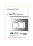
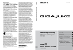
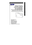
3.11 Connect a two conductor power cable to the AC 24V or DC 12V input on the
rear of the camera. See figure 1.
3.12 Apply AC 24V or DC 12V power to the camera.
3.13 Adjust the camera back focus, lens focus and iris controls for an optimum
picture.
NOTE: Do not aim or point the camera toward the sun or into a strong light.
12V DC / 24V AC
CLASS2
Use UL Listed Class 2 Power Transformer, 24V
AC or 12V DC power adapter. When using 12V
DC power adapter, connect+ pole to + position
and , pole to position. Only use a Class 2
Power Source.
~+ G
~
FIGURE 1.
8
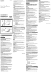
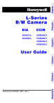
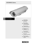
< Model: KC450xMP/KC650xMP >
6. Video Out BNC Connector
4. Stand Mount Bracket(up)
AGC
3. Auto Iris Connector
BLC
A/I
1. C/CS Back Focus
Adjust Ring
F/F
x
E/I
x
2. Back Focus Lock Screw
3. Auto Iris
Connector
5. Function
Switch
2. Back Focus
Lock Screw
6. Video Out BNC Connector
1. Back Focus
AdjustRing
KC650xMP
7. Stand Mount Bracket(down)
1. C/CS Back Focus
Adjust Ring
6. Video Out BNC
Connector
9. Power LED
9. Power LED
6. Video Out BNC
Connector
VIDEO OUT
VIDEO OUT
AC 230V IN
12VDC/24VAC
CLASS 2
PWR
8. Power Cord
8. Power Input
Terminal
FIGURE 2.
9
~ +
G
-
PWR
~
6. Video Out BNC
Connector
4 MAJOR OPERATION CONTROLS AND THEIR FUNCTIONS (CONT.)
4.1 C/CS Back Focus Adjustment Ring
This ring is used to adjust the back focal length or picture focus by rotating
this ring clockwise for the C-mount and counter-clockwise for the CS-mount
lens.
4.2 Back Focus Lock Screw
This screw is used to lock the back focus adjustment ring.
4.3 Auto Iris Connector
This 4-pin female connector supplies the power and either video signal or DC
control signal to the auto iris lens.
A 4-pin male connector, which can be mated with the camera's female
connector, is supplied as a standard accessory. This male connector can be
installed on any auto iris lens.
4.4 Mounting Bracket Hole
This threaded hole (1/4"-20) is used to mount the camera onto a mounting
bracket or tripod.
4.5 Function Switch
Switch Alignment
* Except A/I, AGC
A. AGC (auto gain control) / (ON/OFF) / (Sw6)
This feature keeps signals at a constant level. This control is very useful while
using the camera at low light levels and when light levels change over time.
10
B.
(gamma correction) / (ON/OFF) (Sw5)
ON .45 correcton for non-linearity gain response in the monitor.
OFF No correction.
C. BLC (back light compensation) / (ON/OFF) (Sw4)
his adjustment is used to place the BLC function of camera into preset mode.
Except for OFF mode, the camera will automatically try to maintain proper
exposure in the specific area of each mode even if brightness changes.
BLC mode may be selected manually, OFF, TOP, BOTTOM or CENTER.
Status
BLC (Sw4)
ON
BLC SIZE 40% OF CENTER
OFF
BLC OFF
D. A/I (auto iris) (video / DC) (Sw3)
This switch is used to select the appropriate auto iris control signal to the lens.
DC: Choose this position when the auto iris lens requires DC control signal
VIDEO: Choose this position when the auto iris lens requires video signal.
Position of switch
Status of A/I
Status of E/I
Toward front of the camera
Video
OFF
Toward back of the camera
DC
OFF
E. F/F (Flicker Free) / (ON / OFF) (Sw2)
This function is used for removing flicker, when camera signal format does not
coincide with power source frequency in the area of camera used.
CAMERA TV MODE F/F MODE SHUTTER
EIA
1/100 sec
CCIR
1/120 sec
11
F. E/I (electronic iris) / (ON/OFF) (Sw1)
Automatically varies the camera's shutter to mimic auto iris control, allowing
fixed or manual iris lenses to be used in a wider range of applications.
When this function is used, turn off the F/F function (SW2).
G. Phase Adjustment (Potentiometer)
Phase adjustment is used in a multi-camera system when power is supplied
from different sources, causing the camera to be out of phase. This situation
affects auto-switching of the cameras by causing a vertical flip or roll during
the switch interval. The vertical phase adjustment allows the camera's line
lock sync to be adjusted from 0 to 360 degrees with reference to the zero line
crossing of the AC power source.
A. Ensure that all cameras are powered from the same electrical source
and wired in a similar fashion.
B. Adjust the phase control on the back of the camera until there is no
vertical flip or roll on the monitor when using an auto-switcher.
H. Iris Adjustment Pot (Potentiometer)
This control adjusts the level of the auto iris when the A/I lens selection
switch is set to the DC position and a DC lens is mounted on the camera.
The switch should be in the video position when an auto iris video lens is
mounted on the camera. If a video auto iris lens is used, this adjustment has
no function.
4.6 Video Output Connector (BNC)
A 1.0Vp-p / 75 ohms composite video signal is provided at this connector.
4.7 Power Input Terminal / Power Cord
The terminal accepts, AC 24V ± 10%, 50 Hz or DC 12V ± 10% using
UL Listed class 2 power supply only and the cord models accept
230 VAC ± 10%, 50 Hz
CAUTION: Connect to AC 24V or DC 12V using UL Listed class 2 power
supply only.
4.8 Power LED
The LED light is green, while power is supplied to the camera.
12
5 LENS ADJUSTMENT
5.1 MANUAL IRIS LENS
When using a manual iris lens, turn the iris ring on the lens to the OPEN
position and adjust the manual iris for the appropriate range. Adjust during
the brightest conditions, opening the lens without saturating the picture. Set
the EI switch to ON. Adjust the lens opening for the minimum F-number
yielding a good picture under the brightest scene conditions.
The manual iris is used in indoor applications where lighting from windows
can considerably affect the light level of the room.
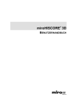
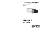
5.2 Video-type Auto Iris Lens
To install and adjust a video-type auto-iris lens, do the following:
A. Thread the auto-iris lens on to the lens mount on the front of the camera.
(See Figure 3)
FIGURE 3.
13
B. If necessary, solder the lens control wires to the connector supplied with
the camera.
Connector
Cover
Rib
Pin3
Automatic
Iris Lens
Pin1
Heat
Pin 4
Shrinkable
Tubes
IrisControl
Pin2
Cable
Pin
1
2
3
4
Name Wire Color
Red
Voltage +
Open
Video
White
Ground
Black
Connector
Figure 4.
C. Plug the connector into the auto iris jack on the top of the camera.
The connector is polarized and can only be inserted into the jack one
way.
D. The EI switch should be in the OFF position.
E. The A/I switch should be in the VIDEO position.
F. Apply power to the camera.
G. Adjust the focus ring on the lens for an optimum picture. If a picture is not
visible, set the lens for proper exposure by adjusting the ALC (automatic
level control) and level on the lens. The ALC setting can range between
Average (average) or PK (peak).
A midrange setting is appropriate for most applications.
For ALC adjustments:
AVG To slow the reaction of the lens to changing light, set the range to
the AVG setting to average the video level from the camera. Use
when there are bright spots in the picture such as lights or glare
from the sun.
PK
To increase the speed of the lens reaction to the changing light, set
the lens adjustment to PK so the lens will adjust to the brightest or
peak object in the video.
Use this setting if you want to see the brightest object and not the
background objects.
14
For Level adjustments:
Adjust the level control for the best picture during the day.
A night adjustment may not provide the proper setting for controlling the
light during the day.
H. Set the back focus of the camera before the final adjustment of the video
Level.
I. If the auto iris has a gain adjustment:
• If the lens oscillates between open and closed under bright lights, slowly
turn the gain adjustment counter clockwise until the oscillating stops.
• Increase the light getting to the camera by adjusting the level control
and readjusting the gain control as noted in step G.
5.3 DC-TYPE AUTO IRIS LENS
To install and adjust a DC-type auto-iris lens, do the following:
A. Thread the auto-iris lens onto the lens mount on the front of the camera.
(see figure 3.)
B. Solder the lens control wires to the connector supplied with the camera.
If using Ultrak cameras & lenses, this step is not necessary.
Connector
Cover
Rib
Pin 3
Automatic
IrisLens
Pin 1
Heat
Pin4
Shrinkable
Tubes
Pin 2
Iris Control
Cable
Connector
Figure 5.
15
Pin
1
2
3
4
Name
Damp Coil Damp Coil +
Drive Coil +
Drive Coil -
Wire Color
Blue
Red
White
Green
C. Plug the connector into the auto iris jack on the top of the camera.
The connector is polarized and can only be inserted into jack one way.
D. The EI switch should be in the OFF position.
E. The A/I switch should be in the DC position.
F. Apply power to the camera.
G. Adjust the auto-iris lens for an optimum picture using the IRIS (A) control
on the top of the camera.
5.4 BACK FOCUS ADJUSTMENT
For best results, perform back focus adjustments at night or while using a #6 or
#8 welders glass in front of the lens. The focus of the camera will change
slightly if the camera iris was adjusted on a light scene, then changes to a dark
scene. However, the camera will remain in focus if the iris was focused on a
dark scene and the scene lightens.
A. After mounting the lens apply power to the camera.
B. If a picture is visible, focus on the scene. If the picture is not visible, open
the iris on the lens. Open the lens as wide as possible by placing the welder's
glass in front of the lens and forcing the lens to automatically open.
C. When the iris is open to the widest point, readjust the focus for a clear picture.
If a clear picture is not possible, set the focus ring to midrange.
D. Loosen the back focus lock screw.
E. Adjust the back focus ring for a clear picture.
F. Tighten the back focus lock screw.
G. Fine tune the focus with the focus ring on the lens.
H. Remove the welders glass from in front of the lens.
I. Adjust the iris of the lens for the best picture quality.
16
5.5 ZOOM LENS BACK FOCUS ADJUSTMENT
The objective of back focusing a zoom lens is similar to that of a fixed focal
length camera, except that back focus is also adjusted to maintain the focus
when "zooming" the lens in and out on a scene.
A. Choose an object at the farthest range that you wish to look at with a zoom
lens.
B. Make sure the iris of the lens is wide open. (Do this by adjusting the camera
at night or use a welder's glass in front of the lens.)
C. Set the focus on the lens to the far range.
D. Adjust the zoom on the lens to obtain the widest picture.
E. Loosen the back focus lock screw.
F. Adjust the focus adjust ring for the clearest picture.
G. Tighten the back focus lock screw.
H. Adjust the zoom on the lens to the far telephoto position.
I. Adjust the back focus ring for the clearest picture.
J. Adjust the zoom on the lens back to the widest picture.
K. Loosen the back focus lock screw.
L. Readjust the back focus for the clearest picture.
M. Tighten the back focus lock screw.
N. Repeat the previous steps, as many times as necessary, to maintain a clear
picture through the entire zoom range.
17
6 TROUBLESHOOTING
If problems occur, verify the installation of the camera with the instructions in this
manual and with other operating equipment.
Isolate the problem to the specific piece of equipment in the system and refer to
the equipment manual for further information.
Problem
No Video
Possible Solution
1. Verify power to all pieces of equipment in the
system. (Camera green LED on)
2. Verify that the video cables are connected
correctly.
3. Verify that the lens cap has been removed
from the lens or that the iris of the lens is open.
Video, but no function 1. Power down the system for one minute, then
turn power back ON.
Dark video
1. Adjust iris. Check AI connections.
7 MAINTENANCE
Preventive maintenance allows detection and correction of minor faults before
they become serious and cause equipment failure.
Yearly maintenance on video equipment should include the following:
A. Inspect all connecting cables for deterioration or other damage.
B. Clean components with a clean damp cloth.
C. Verify that all the mounting hardware is secure.
18
8 SPECIFICATIONS
8.1 B/W Cameras
Power
• Power Source
• Power Consumption
• Power Indicator
Sensor Information and General
• Processing Technology
• Image Sensor
• Picture Element
• Chip Size
• Unit Cell Size
• Scanning System
• Scanning Frequency
• Sync System
• Vert Phase Adjust Range
• Electronic Shutter
• Operating Temperature / Humidity
Video
• Signal Format
• Resolution
• Minimum Illumination
• Video Output
• Video Iris Output
• S/N Ratio
• BLC Size
• Sync Level
• White Clip
• Shutter Control
• Flickerless mode
• Auto Iris
• BLC
• Gamma
• AGC
• Vert Phase Adjust
• DC Iris Level Adjust
Connector and Mechanical
• Video Output
• Power Input
• AI/DC Output
• Lens Mount
• Back Focus & C/CS Adjust
• B/F & C/CS Lock
• Mounting Hole
• External Dimensions
• Weight
12V DC/24V AC± 10%, 50Hz or
230 VAC ± 10%, 50Hz
Max. 2.5 Watts at 12VDC/24VAC, MAX 5.5Watts at 230VAC
Green LED
Sony
1/3" interline transfer CCD
KC450xMP 500(H) X 582(V)
KC650xMP 752(H) X 582(V)
6.0mm(H) x 4.96mm(V)
KC450xMP 9.8um(H) x 6.3um(V)
KC650xMP 6.5um(H) x 6.25um(V)
2:1 interlace
15.625KHz(H), 50Hz(V)
Line Lock(But Internal at 12VDC)
0 deg. to 300 deg
1/50 ~ 1/100,000 sec.
-10°C - +50°C (14°F - 122°F) / <96% (Non-condensing)
CCIR 625 Lines
KC450xMP 380 TV Lines
KC650xMP 570 TV Lines
0.08 Lux(F1.4)
1.0Vp-p, 75 ohm
650mV at video out 1.0 Vp-p
46 dB (AGC Off)
40% center (BLC on)
39 ~ 41 IRE
120 IRE
Auto(On), 1/50 (Off) (Dip Switch)
1/120(On), 1/50(Off) (Dip Switch)
VIDEO/DC (Dip Switch)
ON/OFF (Dip Switch)
On(0.45)/Off(1) (Dip Switch)
On/Off
(Dip Switch)
Adjustable
(Potentiometer)
Adjustable
(Potentiometer)
BNC Connector
3-pin Terminal Block at 12VDC/24VAC model,
Power cord at 230VAC model
4-pin mini din jack
(Standard Connection)
C/CS(selected through back focus)
Built in Back Focus Cam with Thumb Wheel Adjust
(Range:-1.5mm to +6.5mm)
Phillips Tension Screw
1/4"-20 UNC Top and Bottom
62(W) x 54(H) x 140(D)
270g ( ~9.5 oz) at 12VDC / 24VAC model,
580g(~20.5 oz) at 230VAC model
19
Rev - Part 1000010 12/8
Warnung:
Um die Gefar von Feuer und elektrischen Schlages zu verringern, darf dieses Produkt
keinesfalls Regen und Feuchtigkeit ausgesetzt werden. Keine Metallfremdgegenstände in
die Lüftungsschlitze einführen
VORSICHT
Gefahr eines
elektrischen Schlages!
Nicht öffen
Vorsicht: Um die Gefahr eines elektrischen Schlages zu verrigern darf die Abedckung bzw, das Gehäuse
nicht entfernt werden. Es befinden sich keine Bauteile im Gerät, die vom Anwender gewartet werden
dürfen. Reparaturen dürfen nur von qualifiziertem Fachpersonal durchgeführt werden
Erklärung der Symbole
Dieses Symbol (Blitz in einen gleichseitigen Dreieck) weist den Anwerder darauf
hin, daß im Geräteinneren nicht-isolierte Spannung vorhanden ist und die Gefahr
eines elektrischen Schlages besteht.
Dieses Symbol (Ausrufzeichen in einem gleichseitigen Dreieck) weist den Anwender
auf wichtige Hinweise über den Betrieb und die Wartung (Kundendienst) hin, die in
der im Lieferumfang enhaltenen Anleitung erläutert werden.
DIE ANWENDER DIESES
GERÄTS SIND ZUR
EINHALTUNG SÄMTLICHER
GELTENDER GESETZLICHER
BESTIMMUNGEN AUF
BUNDES- UND
LÄNDEREBENE ÜBER DIE
ÜBERWACHUNG UND
AUFZEICHNUNG VON BILDUND TONSIGNALEN
VERANTWORTLICH.
ULTRAK SCHLIESST HIERMIT
DIE HAFTUNG FÜR
GESETZESWIDRIGEN
GEBRAUCH DIESES GERÄTS
AUS.
WICHTIGE SICHERHEITSHINWEISE
1.
2.
3.
4.
5.
6.
6A.
7.
8.
9.
10.
11.
12.
13.
14.
15.
16.
17.
18.
LESEN DER BEDIENUNGSANLEITUNG — Lesen Sie vor Inbetriebnahme dieses Geräts die Bedienungsanleitung und die
Sicherheitshinweise sorgfältig und vollständig durch.
AUFBEWAHREN DER BEDIENUNGSANLEITUNG — Bewahren Sie diese Anleitung auf, um die enthaltenen Informationen jederzeit
nachschlagen zu können.
REINIGUNG — Vor jedem Reinigen des Monitors und der Zusatzgeräte muß das Netzkabel aus der Steckdose gezogen werden. Verwenden
Sie keine flüssigen oder aerosolhaltigen Reinigungsmittel, sondern ein leicht angefeuchtetes Tuch.
ZUBEHÖR — Verwenden Sie ausschließlich vom Hersteller empfohlenes Zubehör, da anderenfalls die Gefahr von Feuer, eines elektrischen
Schlages oder Personenschadens besteht.
WASSER UND FEUCHTIGKEIT— Halten Sie alle Geräte von Flüssigkeit, Feuchtigkeit u.ä. Fern.
AUFSTELLUNG — Stellen Sie die den Monitor und die Zusatzgeräte nur auf standfeste Unterlagen, um eine Verletzungsgefahr für Personen
und eine Beschädigung der Geräte zu vermeiden. Bei Wand- oder Regalmontage sind die Herstellerangaben zu beachten bzw. Ein vom
Hersteller empfohlenes Montageset zu benutzen.
Gehen Sie beim Bewegen des Monitors, der Zusatzgeräte und Rollgestelle behutsam vor. Ruckartiges Anhalten, übertrieben kräftige
Bewegungen oder unebener Untergrund können zum Umkippen eines Rollgestells führen und somit die Geräte beschädigen.
BELÜFTUNG — Zur Belüftung der Geräte sind Schlitze und Öffnungen im Gehäuse an der Geräterück- bzw. -unterseite vorhanden,
die vor Überhitzung schützen und den zuverlässigen Betrieb der Geräte gewährleisten. Beim Aufstellen des Monitors muß darauf geachtet
werden, daß die Lüftungsschlitze und -öffnungen nicht blockiert oder bedeckt werden. Ungeeignete Aufstellungsorte sind deshalb ein Bett,
Sofa, eine Decke oder ähnliches. Monitor und Zusatzgeräte nicht auf Wärmequellen wie Heizkörper oder Warmluftauslässe bzw. In deren
Nähe stellen. Beim Einbau des Monitors bzw. Signalempfängers in Schrankwände oder ähnlichem muß für ausreichende Belüftung gesorgt
werden.
SPANNUNGSVERSORGUNG — Die Betriebsspannung Ihres Monitors oder Zusatzgeräts entnehmen Sie bitte der Beschriftung am Gerät.
Falls Sie die Art der Spannungsversorgung am Aufstellungsort des Monitors nicht sicher wissen, wenden Sie sich bitte an Ihren Händler oder
das örtliche Stromversorgungsunternehmen. Hinweise zu batteriebetriebenen Monitoren oder Zusatzgeräten sind der jeweiligen
Bedienungsanleitung zu entnehmen.
ERDUNG UND VERPOLSCHUTZ — Der Monitor bzw. Das Zusatzgerät ist mit einem Netzstecker mit Verpolschutz ausgestattet. Der Stecker
paßt deshalb nur in einer Position in die Steckdose. Dies ist eine Sicherheitsmaßnahme. Läßt sich der Stecker nicht vollständig in die
Steckdose einführen, drehen Sie den Stecker um und probieren es erneut. Paßt der Stecker noch immer nicht in die Steckdose, wenden Sie
sich bitte an einen Elektriker, der Ihre Steckdose austauschen kann. Manipulieren Sie unter keinen Umständen den Stecker, da Sie dadurch
diese Sicherheitsfunktion außer Kraft setzen.
NETZKABEL — Stellen Sie keine Gegenstände auf das Netzkabel. Stellen Sie den Monitor oder das Zusatzgerät so auf, daß niemand auf das
Netzkabel tritt.
WARNUNGEN BEACHTEN — Beachten Sie alle am Monitor oder Zusatzgerät angebrachten Warnungen und Hinweise.
BLITZEINSCHLAG — Zum Schutz des Monitors oder der Zusatzgeräte vor Blitzeinschlag und wenn die Geräte längere Zeit nicht benutzt
werden, sollte das Netzkabel aus der Steckdose gezogen werden und die Antenne und Verkabelung getrennt werden. So ist Ihr Gerät vor
Beschädigung durch eventuelle Spannungsspitzen und bei Gewitter geschützt.
ÜBERLAST — Die Steckdosen und Verlängerungskabel müssen vor Überlast geschützt werden, da sonst die Gefahr von Feuer oder eines
elektrischen Schlages besteht.
EINDRINGEN VON FREMDKÖRPERN UND FLÜSSIGKEIT — Stecken Sie keine Gegenstände durch die Öffnungen in den Monitor oder die
Zusatzgeräte, da diese spannungsführende Teile kontaktieren oder einen Kurzschluß auslösen könnten und die Gefahr von Feuer oder eines
elektrischen Schlages besteht. Achten Sie darauf, daß keine Flüssigkeit in das Gerät gelangen kann.
REPARATUR — Führen Sie keine Reparaturen am Monitor oder Zusatzgerät aus, da Sie sich durch das Öffnen bzw. Abnehmen der
Abdeckungen Gefahren durch Hochspannung aussetzen. Reparaturen und Kundendienst sind ausschließlich von qualifiziertem Fachpersonal
durchzuführen.
SCHÄDEN, DIE EINE REPARATUR ERFORDERLICH MACHEN — Ziehen Sie in folgenden Fällen das Netzkabel des Monitors oder
Zusatzgeräts aus der Steckdose und wenden Sie sich an einen qualifizierten Kundendienst:
A. Bei Beschädigung des Netzkabels oder Netzsteckers.
B. Wenn Flüssigkeit oder Gegenstände in das Gerät gelangt sind.
C. Wenn das Gerät Regen oder Wasser ausgesetzt war.
D. Wenn das Gerät trotz Einhaltung der Bedienungsanleitung Funktionsstörungen aufweist, stellen Sie bitte nur die Bedienelemente nach, die
in der Bedienungsanleitung erklärt werden. Die unsachgemäße Benutzung anderer Einstellelemente kann zu einem Schaden am Gerät
führen, und die Rücksetzung des Geräts auf Normalbetrieb durch einen qualifizierten Techniker erfordert erheblichen Zeitaufwand.
E. Wenn ein Gerät herunterfiel oder das Gehäuse beschädigt ist.
F. Wenn sich das Betriebsverhalten eines Geräts auffällig verändert ein untrügliches Zeichen, daß ein Kundendienst erforderlich ist.
ERSATZTEILE — Bitte vergewissern Sie sich, daß der Kundendienst ausschließlich vom Hersteller empfohlene Originalersatzteile bzw.
Gleichwertige Ersatzteile verwendet. Ansonsten bestehen die Gefahr von Feuer, eines elektrischen Schlages u.a.
SICHERHEITSÜBERPRÜFUNG — Nach allen Reparatur- oder Kundendienstarbeiten sollte eine Sicherheitsüberprüfung durch einen
qualifizierten Techniker erfolgen, um den einwandfreien Betriebszustand des Geräts sicherzustellen.
1 AUFGABE
Die 1/3 Zoll (8,5 mm) CCD-Schwarzweiß-Überwachungskamera liefert SONY
Bildqualität speziell für interne Fernsehanlagen und
Fernsehüberwachungsanlagen.
Die Kamera besitzt:
• Hochleistungsfähige 1/3 Zoll (8,5 mm) Sony CCD-Technologie
• 380-Zeilen-Auflösung (KC450xMP), 570-Zeilen-Auflösung (KC650xMP)
• 0,08 Lux bei F1,4 Empfindlichkeit
• C/CS, Nocke zur leichten Einstellung der Bildschnittweite
• Automatischer elektronischer Verschluß und handeinstellbare elektronische
Verschlußzeiten von 1/50 bis 1/100.000
• Aufnahme von automatischen Blendenobjektiven oder GS-Objektiven mit DIPSchalterwahl
• Schnellanschluß für automatisches Blendenobjektiv oder GS-Objektiv mit 4poliger Steckverbindung
• Verstellbarkeit für Gegenlicht, Gamma und automatische Verstärkungsregelung
• 230 V~ oder 12 V=/24V~ Schaltnetzteil
• Begrenzte Dreijahresgarantie
Die Anleitung beschreibt die Installation und Bedienung der Kamera.
2 VORSICHTSMASSNAHMEN BEI DER INSTALLATION
A. Auswahl einer passenden Anbringungsstelle für die Kamera. Anbringung des
Kameraständers oder der Halterung an der gewählten Stelle mit Hilfe
geeigneter Schrauben. Der Kameraständer oder die Halterung muß an einem
tragenden Bauteil befestigt werden, wie zum Beispiel an einem Wandpfosten
oder Deckensparren, der das Gewicht der Kamera und der Halterung
unterstützen kann. Die Mindestbelastbarkeit der Befestigung beträgt 5 kg (11
lb).
B. Wenn sie erforderlich sind, sollten nur UL-registrierte Netztransformatoren der
Schutzklasse 2 für 24 V~ oder 12 V= verwendet werden.
21
3 SYSTEMINSTALLATION
Die Installation der Kamera muß von qualifiziertem Wartungspersonal unter
Berücksichtigung aller lokalen und Bundesvorschriften für elektrische und
mechanische Installationen vorgenommen werden. Die Installation der
Kamera umfaßt die folgenden Schritte.
3.1 Auspacken aller Teile und Identifizierung der zur Installation benötigten
Gegenstände:
• Kamera
• Bedienungsanleitung
• Mini-DIN-Stecker (für automatische Video- oder GS-Blendenobjektive)
3.2 Weitere eventuell bei der Installation benötigte Gegenstände, die NICHT
zum Lieferumfang der Kamera gehören:
• Kameraobjektiv
• Videokabel
• Kameraständer oder Halterung
• Spannungsquelle für 24 V~ oder 12 V=
• Befestigungsteile
• Monitor
• Werkzeuge für die Installation
3.3 Auswahl einer passenden Anbringungsstelle für die Kamera. Anbringung des
Kameraständers oder der Halterung an der gewählten Stelle mit Hilfe einer
geeigneten Schraube. Der Kameraständer oder die Halterung muß an einem
tragenden Bauteil befestigt werden, wie zum Beispiel an einem Wandpfosten
oder Deckensparren, der das Gewicht der Kamera und der Halterung
unterstützen kann. Die Mindestbelastbarkeit der Befestigung beträgt 5 kg (11
lb).
3.4 Die Kamera besitzt Befestigungslöcher an der Unter- und Oberseite des
Kameragehäuses zur unteren oder oberen Befestigung. Das 1/4-Zoll-20 UNC
Gewindeloch kann auf den Stift des Kameraständers oder der Halterung
aufgeschraubt werden.
22
3.5 Aufsetzen des Objektivs. Einstellung des Rings für die Bildschnittweite auf das
verwendete Objektiv, im Fall der die C-Fassung im Uhrzeigersinn oder im Fall
der CS-Fassung entgegen dem Uhrzeigersinn.
3.6 Bei Verwendung eines automatischen Blendenobjektivs wird das Objektivkabel
an den mit der Kamera gelieferten Mini-DIN-Stecker angeschlossen.
3.7 Einführen des Objektivsteckers in die Kamerasteckverbindung für das
automatischen Blendenobjektiv.
3.8 Verlegen des Videokabels vom Monitor zur Kamera.
3.9 Einstecken des Kabels in den BNC-Ausgangsstecker mit der Bezeichnung
“Video Out” ("Video aus") an der Rückseite der Kamera.
3.10 Einstecken des anderen Kabelendes in den Video-Eingangskanal an der
Rückseite des Monitors.
Für Modelle mit 230 V~:
3.11 Einstecken des Netzkabels in die Steckdose.
3.12 Anlegen von 230 V~ an die Kamera.
Für Modelle mit 12 V= oder 24 V~:
3.11 Anschließen eines 2-adrigen Stromkabels an den Eingang für 24 V~ oder 12
V= an der Rückseite der Kamera. Siehe Abbildung 1.
3.12 Anlegen von 24 V~ oder 12 V= an die Kamera.
3.13 Bildoptimierung durch Einstellen der Bildschnittweite, der Objektivbrennweite
und der Blendenregelung der Kamera.
NOTE: Do not aim or point the camera toward the sun or into a strong light.
~+ G
~
UL-registrierten Netztransformator der
Schutzklasse 2 verwenden, Netzadapter für 24
V~ oder 12 V=. Bei der Verwendung eines
Adapters für 12 V= wird der Pluspol + an Plus +
und der Minuspol an Minus angeschlossen.
Nur eine Spannungsquelle der Schutzklasse 2
verwenden.
ABBILDUNG 1.
23
< Modell: KC450xMP/KC650xMP >
6. BNC-Stecker für 'Video Aus'
4. Stativfestigung (nach oben)
AGC
3. Steckverbindung für die automatische Blende
BLC
A/I
1. C/CS-Einstellring für
die Bildschnittweite
F/F
x
E/I
x
2. Feststellschraube für die Bildschnittweite
3. Steckverbindung für die
automatische Blende
5. Funktionsschalter
2. Feststellschraube
für die Bildschnittweite
1. Einstellring
für die
Bildschnittweite
6. BNC-Stecker für 'Video Aus'
KC650xMP
7. Stativbefestigung (nach unten)
1. C/CS-Einstellring für
die Bildschnittweite
6. BNC-Stecker für
'Video Aus'
9. Netz-LED
9. Netz-LED
6. BNC-Stecker
für 'Video Aus'
6. BNC-Stecker
für 'Video Aus'
VIDEO OUT
VIDEO OUT
AC 230V IN
12VDC/24VAC
CLASS 2
PWR
8. Netzkabel
PWR
8.Stromanschluß
~ +
ABBILDUNG 2.
24
G
-
~
4 DIE WICHTIGSTEN BEDIENELEMENTE UND IHRE FUNKTIONEN (FORTS.)
4.1 C/CS-Einstellring für die Bildschnittweite
Dieser Ring dient zur Einstellung der Bildschnittweite oder des
Bildbrennpunktes, indem der Ring im Fall der C-Fassung im Uhrzeigersinn
oder im Fall der CS-Fassung entgegen dem Uhrzeigersinn gedreht wird.
4.2 Feststellschraube für die Bildschnittweite
Diese Schraube dient zur Feststellung des Einstellrings für die
Bildschnittweite.
4.3 Steckverbindung für die automatische Blende
Die vierpolige Steckerbuchse dient zur Beistellung des Stroms und entweder
des Videosignals oder des GS-Steuersignals für das automatische
Blendenobjektiv.
Ein vierpoliger, in die Steckerbuchse der Kamera passender Stecker wird als
Standardzubehör mitgeliefert. Der Stecker kann an jedes beliebige
automatische Blendenobjektiv angeschlossen werden.
4.4 Befestigungsloch
Das Gewindeloch (1/4 Zoll-20) dient zur Befestigung der Kamera an einem
Befestigungsteil oder auf einem Stativ.
Schalterabgleich
* Außer für automatische Blende
A. AGC (automatische Verstärkungsregelung)/(EIN/AUS) / VIDEO (Sch6)
Mit dieser Einrichtung wird das Signal konstant gehalten. Die Regelung ist
bei der Verwendung der Kamera bei schwachem und zeitlich veränderlichem
Licht besonders nützlich.
25
B.
(Gamma-Korrektur) / (ON/OFF)(EIN/AUS) (Sch5)
ON (EIN)
0,45 Verstärkungsfehlerkorrektur für den Monitor.
OFF (AUS) Keine Korrektur.
C. BLC (Gegenlichtausgleich) / (ON/OFF)(EIN/AUS) (Sch4)
Mit dieser Einstellung wird der Gegenlichtausgleich der Kamera auf die
Voreinstellung gesetzt. Bei eingeschaltetem Ausgleich versucht die Kamera
automatisch die richtige Belichtung in dem gewählten Feld selbst bei veränderlicher
Helligkeit aufrechtzuerhalten. Der handeinstellbare Gegenlichtausgleich besitzt die
Einstellungen AUS, OBEN, UNTEN oder MITTE.
Status
BLC (Sch4)
EIN
BLC-GRÖSSE 40% DER MITTE
AUS
BLC AUS
D. A/I (automatische Blende)(Video / GS) (Sch3)
Mit diesem Schalter wird das entsprechende automatische Blendensteuersignal für
das Objektiv gewählt.
DC (GS): Erforderliche Stellung, wenn das automatische Blendenobjektiv ein GSSteuersignal verlangt.
VIDEO: Erforderliche Stellung, wenn das automatische Blendenobjektiv ein VideoSteuersignal verlangt.
Schalterstellung
A/I-Status
Belichtungsstatus (E/I)
in Richtung Kameravorderseite
VIDEO
automatische Belichtung(OFF)
in Richtung Kamerarückseite
DC (GS)
Handeinstellung (OFF)
E. F/F (Flimmerfrei) / (ON/OFF)(EIN/AUS) (Sch2)
Diese Funktion dient zur Beseitigung von Flimmern, wenn die Signalform der
Kamera nicht mit der Stromquellenfrequenz am Verwendungsort der Kamera
übereinstimmt.
FERNSEHBETRIEBSWEISE DER KAMERA VERSCHLUSSZEIT BEI F/F-BETRIEB
EIA
1/100 sec
CCIR
1/120 sec
26
F. E/I (elektronische Blende) / (ON/OFF)(EIN/AUS) (Sch1)
Automatische Variierung des Kameraverschlusses zur Imitation der
automatischen Blendenregelung, wodurch für feste oder handeinstellbare
Blendenobjektive ein größerer Anwendungsbereich bereitgestellt wird.
Bei der Verwendung dieser Funktion muß die F/F-Funktion (Sch2)
abgeschaltet werden.
G. Phaseneinstellung (Potentiometer)
Die Anwendung der Phaseneinstellung erfolgt bei Anlagen mit mehreren
Kameras, die den Strom aus diversen Stromquellen beziehen und dadurch
außer Phase geraten. Dieser Zustand zeigt sich bei der automatischen
Umschaltung der Kameras durch vertikales Umkippen oder Laufen des
Bildes während der Umschaltpause. Mit der vertikalen Phaseneinstellung
kann die Zeilensynchronisierung der Kamera von 0 bis 360 Grad bezüglich
dem Wechselstrom-Nulldurchgang verstellt werden.
A. Es ist dafür zu sorgen, daß alle Kameras an dieselbe Stromquelle
angeschlossen sind und gleichartige Verdrahtung besitzen.
B. Einstellung der Phasenregelung an der Rückseite der Kamera bis das
vertikale Umkippen oder Laufen des Bildes auf dem Monitor bei
Verwendung der automatischen Umschaltung eliminiert ist.
H. Potentiometer zur Blendeneinstellung
Mit dieser Einstellung wird die automatische Blende verstellt, wenn der
Wahlschalter für das automatische Blendenobjektiv in der Stellung GS (DC)
steht und der Kamera ein GS-Objektiv aufgesetzt ist. Bei der Verwendung
eines Videoblendenobjectivs auf der Kamera sollte sich der Wahlschalter in
der Stellung ‘Video’ befinden. Bei der Verwendung eines automatischen
Videoblendenobjektivs ist diese Einstellung funktionslos.
4.6 Video-Ausgangsstecker (BNC)
An diesem Stecker steht ein BAS-Signal von 1,0 Vp-p/75 Ohm zur Verfügung.
4.7 Stromanschlußklemme / Netzkabel
Die Stromanschlußklemme dient zur Versorgung mit 24 V~ ± 10%, 50 Hz,
oder 12 V= ± 10%, wobei nur eine UL-registrierte Stromversorgung der
Schutzklasse 2 verwendet werden darf, und die Netzkabelmodelle sind für
230 V~, 50 Hz vorgesehen.
VORSICHT: Der Anschluß an 24 V~ oder 12 V= darf nur unter
Verwendung einer UL-registrierten Stromversorgung der
Schutzklasse 2 erfolgen.
4.8 Netz-LED
Die Leuchtdiode leuchtet grün, solange Strom an die Kamera angelegt ist.
27
5 OBJEKTIVEINSTELLUNG
5.1 HANDEINSTELLBARES BLENDENOBJEKTIV
Zur Verwendung eines handeinstellbaren Blendenobjektivs wird der
Blendenring am Objektiv auf OFFEN gestellt und der passende Bereich der
handeinstellbaren Blende gewählt. Die Einstellung erfolgt unter den hellsten
Bedingungen, wobei das Objektiv geöffnet wird ohne das Bild zu sättigen.
Der Schalter für die elektronischen Blenden (EI) wird auf ON(EIN) gestellt.
Die Objektivöffnung wird auf die kleinste Blendenzahl ‘F’ eingestellt, bei der
sich unter den hellsten Szenenbedingungen ein gutes Bild ergibt.
Die handeinstellbare Blende wird bei Innenaufnahmen verwendet, wo
Fensterlicht einen bedeutenden Einfluß auf die Raumhelligkeit haben kann..
5.2 Automatisches Videoblendenobjektiv
Das Anschließen und Einstellen eines automatischen Videoblendenobjektivs
erfolgt mit den folgenden Schritten:
A. Einschrauben des automatischen Blendenobjektivs in die Objektivfassung
an der Vorderseite der Kamera. (Siehe Abbildung 3).
ABBILDUNG 3.
28
B. Falls nötig werden die Drähte für die Objektivsteuerung an den
mitgelieferten Mini-DIN-Stecker angelötet.
Rippe
Steckergehäuse
Automatisches
Blendenobjektiv
Stift 3
Stift 1
Stift
1
Stift 4
Warmschrumpfschlauch
Stift 2
2
Blendensteuerkabel
3
4
Name
Drahtfarbe
Spannung +
Rot
frei
Video
Weiß
Erde
Schwarz
Stecker
Abbildung 4.
C. Einführen des Steckers in die Buchse für die automatische Blende an der
Oberseite der Kamera. Der Stecker ist gepolt und kann nur in einer
bestimmten Weise in die Buchse eingeführt werden.
D. Der Schalter (EI) für die elektronischen Blenden sollte in der Stellung
OFF(AUS) stehen.
E. Der Schalter (A/I) für die automatischen Blenden sollte in der Stellung
VIDEO stehen.
F. Anschließen des Stroms an die Kamera.
G. Bildoptimierung durch Einstellung des Entfernungsrings des Objektivs. Falls
kein Bild zu sehen ist, muß das Objektiv für die passende Belichtung
eingestellt werden, indem die automatische Helligkeitsaussteuerung (ALC /
automatic level control) und die Helligkeit am Objektiv eingestellt werden.
Der Einstellungsbereich der automatischen Helligkeitsaussteuerung liegt
zwischen Mittel (AVG / average) und Hoch (PK / peak).
In den meisten Fällen liegt die passende Einstellung im Mittelbereich.
Einstellung der Helligkeitsaussteuerung (ALC):
AVG (Mittel) Zur Verlangsamung der Reaktion des Objektivs auf
Lichtänderungen wird Mittel (AVG) eingestellt, um die
Videohelligkeit der Kamera zu mitteln. Diese Einstellung
sollte beim Vorliegen von hellen Bildstellen wie zum Beispiel
Lampen oder Sonnenreflexen verwendet werden
PK (Hoch )
Zur schnelleren Reaktion des Objektivs auf Lichtä
nderungen wird Hoch (PK) eingestellt, damit sich das Objektiv
auf den hellsten Gegenstand im Bild einstellt.
Diese Einstellung sollte verwendet werden, wenn die hellsten
Bildstellen und nicht der Hintergrund beobachtet werden sollen.
29
Einstellung der Helligkeit:
Das beste Bild wird durch Einstellung der Helligkeit bei Tag erreicht.
Eine Einstellung bei Nacht erzielt unter Umständen nicht die richtige
Lichtsteuerung bei Tag.
H. Die Bildschnittweite der Kamera wird vor der endgültigen Einstellung der
Videohelligkeit eingestellt.
I. Bei automatischer Blende mit einstellbarer Signalverstärkung:
• Beim Pendeln des Objektivs in hellem Licht zwischen 'auf' und 'zu' wird die
Einstellung der Signalverstärkung langsam entgegen dem Uhrzeigersinn
verstellt bis das Pendeln aufhört.
• Zur Erhöhung des in die Kamera eintretenden Lichtes wird die
Helligkeitsregelung verstellt und bei Bedarf die Signalverstärkung nochmal
neu eingestellt gemäß der Beschreibung von Schritt G.
5.3 AUTOMATISCHES GS-BLENDENOBJEKTIV
Das Anschließen und Einstellen eines automatischen GS-Blendenobjektivs
erfolgt mit den folgenden Schritten:
A. Einschrauben des automatischen Blendenobjektivs in die Objektivfassung
an der Vorderseite der Kamera. (Siehe Abbildung 3.)
B. Anlöten der Drähte für die Objektivsteuerung an den mitgelieferten Stecker.
Bei Verwendung von Ultrak Kameras und Objektiven ist dieser Schritt
nicht nötig.
Rippe
Automatisches
Blendenobjektiv
Stift 1
Stift 4
Stift 2
Stift
Steckergehäuse
Stift 3
Warmschrumpfschlauch
Blendensteuerkabel
Stecker
Abbildung 5.
30
1
Name
Dämpferspule -
2
Dämpferspule +
Rot
3
Antriebsspule +
Weiß
4
Antriebsspule -
Grün
Drahtfarbe
Blau
C. Einführen des Steckers in die Buchse für die automatische Blende an der
Oberseite der Kamera. Der Stecker ist gepolt und kann nur in einer
bestimmten Weise in die Buchse eingeführt werden.
D. Der Schalter (EI) für die elektronischen Blenden sollte in der Stellung
OFF(AUS) stehen.
E. Der Schalter (A/I) für die automatischen Blenden sollte in der Stellung GS
(DC) stehen.
F. Anschließen des Stroms an die Kamera.
G. Bildoptimierung durch Einstellung des automatischen Blendenobjektivs an
BLENDENEINSTELLUNG (A) an der Oberseite der Kamera.
5.4 EINSTELLUNG DER BILDSCHNITTWEITE
Die besten Ergebnisse werden bei einer Einstellung der Bildschnittweite bei Nacht
erreicht oder unter Verwendung einer Schweißglasscheibe Nr. 6 oder Nr. 8 vor dem
Objektiv. Wenn die Einstellung der Kamerablende an einer hellen Szene erfolgt, tritt
beim Übergang zu einer dunklen Szene eine geringe Änderung des Brennpunktes
der Kamera ein. Dagegen bleibt die Schärfe der an einer dunklen Szene
eingestellten Kamera beim Übergang zu einer hellen Szene erhalten.
A. Nach dem Ansetzen des Objektivs an die Kamera wird der Strom eingeschaltet.
B. Falls ein Bild sichtbar ist, sollte es scharf eingestellt werden. Falls kein Bild zu
sehen ist, wird die Blende des Objektivs geöffnet. Zur vollständigen Öffnung des
Objektivs wird eine Schweißglasscheibe vor das Objektiv gesetzt, wodurch sich
das Objektiv automatisch öffnet.
C. Bei vollständig geöffneter Blende wird der Brennpunkt neu eingestellt, um ein
scharfes Bild zu erzielen. Falls kein scharfes Bild möglich ist, wird der
Entfernungsring in den Mittelbereich gestellt.
D. Lösen der Feststellschraube der Bildschnittweite.
E. Einstellung eines scharfen Bildes am Ring für die Bildschnittweite.
F. Festziehen der Feststellschraube der Bildschnittweite.
G. Feineinstellung des Brennpunktes mit Hilfe des Entfernungsringes am Objektiv.
H. Entfernen der Schweißglasscheibe vor dem Objektiv.
I. Einstellung der bestmöglichen Bildqualität an der Objektivblende.
31
5.5 EINSTELLUNG DER BILDSCHNITTWEITE BEI VARIO-OBJEKTIVEN
Der Zweck der Einstellung der Bildschnittweite bei einem Vario-Objektiv ähnelt
dem bei Kameras mit Festbrennweite, mit Ausnahme daß die Einstellung
außerdem zum Festhalten des Brennpunktes dient, wenn das Objektiv zum
Heranholen oder Aufziehen einer Szene verwendet wird.
A. Wahl des am weitesten entfernten Beobachtungsgegenstandes für das
Vario-Objektiv.
B. Vollständiges Öffnen der Objektivblende. (Dies erfolgt durch Einstellung
der Kamera bei Nacht oder mit Hilfe einer Schweißglasscheibe vor dem
Objektiv.)
C. Einstellung des Objektivbrennpunktes auf die größte Entfernung.
D. Einstellung der Varioptik auf die Totale.
E. Lösen der Feststellschraube der Bildschnittweite.
F. Einstellung der optimalen Bildschärfe am Einstellring für den Brennpunkt.
G. Festziehen der Feststellschraube der Bildschnittweite.
H. Einstellung der Varioptik auf die größte Entfernung.
I. Einstellung der optimalen Bildschärfe am Ring für die Bildschnittweite.
J. Einstellung der Varioptik zurück auf die Totale.
K. Lösen der Feststellschraube der Bildschnittweite.
L. Neueinstellung der optimalen Bildschärfe über die Bildschnittweite.
M. Festziehen der Feststellschraube der Bildschnittweite.
N. Wiederholung der obigen Schritte so oft wie nötig, bis das Bild über den
gesamten Vario-Bereich scharf ist.
32
6 STÖRUNGSSUCHE UND -BESEITIGUNG
Beim Auftreten von Störungen ist die Installation der Kamera an Hand der
Anweisungen dieser Anleitung sowie im Hinblick auf die übrigen
Betriebseinrichtungen zu überprüfen.
Das störungsbehaftete Geräteteil der Anlage ist einzugrenzen, und weitere
Angaben sind der Geräteanleitung zu entnehmen.
Störung
Kein Video
Potentielle Lösung
1. Überprüfung der Stromversorgung aller Geräte
des Systems. (Die grüne LED der Kamera leuchtet).
2. Prüfung, ob alle Videokabel richtig angeschlossen
sind.
3. Prüfung, ob der Objektivdeckel vom Objektiv
abgenommen und die Objektivblende geöffnet ist
Video, aber
keine Funktion
1. Abschaltung des Systems für eine Minute gefolgt
von der Wiedereinschaltung des Stroms.
Video ist dunkel
1. Einstellung der Blende. Überprüfung der
automatischen Blendenanschlüsse
7 WARTUNG
A. Inspektion aller Verbindungskabel auf Verfall oder anderweitige Beschädigung.
B. Reinigen der Komponenten mit einem sauberen, feuchten Tuch.
C. Überprüfung der Anbringung.
33
8 TECHNISCHE DATEN
8.1 Schwarzweißkameras
Strom
• Spannungsquelle
• Stromverbrauch
• Stromanzeige
Sensordaten und Allgemeines
• Verarbeitungstechnologie
• Bildwandler
• Bildelement
• Chipgröße
• Elementarzellengröße
• Abtastsystem
• Abtastfrequenz
• Synchronisierung
• Einstellbereich der vert. Phase
• Elektronischer Verschluß
• Betriebstemperatur / Feuchtigkeit
12 V=/24 V~ ± 10%, 50 Hz, oder
230 V~ ± 10%, 50 Hz
Max. 2,5 Watt (12 V=/24 V~),
Max. 5,5 Watt (230 V~)
Grüne LED
Sony
1/3 Zoll (8,5 mm) CCD mit Zwischenzeilenübertragung
KC450xMP 500(H) X 582(V)
KC650xMP 752(H) X 582(V)
6,0 mm(H) x 4,96 mm(V)
KC450xMP 9,8 µm(H) x 6,3 µm(V)
KC650xMP 6,5 µm(H) x 6,25 µm(V)
2:1 Zeilensprungfaktor
15,625 kHz(H) x 50 Hz(V)
Zeilensynchronisierung
0 Grad bis 360 Grad
1/50 ~ 1/100000 Sek.
-10°C - +50°C (14°F - 122°F)/ < 96% (nicht kondensierend)
Video
• Signalform
• Auflösung
CCIR, 625 Zeilen
KC450xMP 380 Fernsehzeilen
KC650xMP 570 Fernsehzeilen
0,08 Lux (F 1,4)
• Mindestbeleuchtung
1,0 Vp-p, 75 Ohm unsymmetrisch
• Video-Ausgang
650 mV bei Video-Ausgang 1,0 Vp-p
• Videoblendenausgang
46 dB (bei abgeschalteter automatischer Verstärkungsregelung
• Rauschabstand
(AGC Aus))
40% der Mitte, (bei eingeschaltetem Gegenlichtausgleich
• Gegenlichtausgleichgröße (BLC)
(BLC ein))
39 ~ 41 IRE
• Synchronisationspegel
120 IRE
• Weißbegrenzung
Auto (On)(Ein), 1/50(Off)(Aus) (DIP-Schalter)
• Verschlußregelung
1/120(On)(Ein), 1/50(Off)(Aus) (DIP-Schalter)
• Flimmerfreier Betrieb
Automatische Blende/GS (AI/DC) (DIP-Schalter)
• Automatische Blende
ON/OFF(EIN/AUS) (DIP-Schalter)
• Gegenlichtausgleich (BLC)
On(Ein)(0,45)/Off(Aus)(1) (DIP-Schalter)
• Gamma
(DIP-Schalter)
• Automatische Verstärkungsregelung (AGC) EIN/AUS
Einstellbar
(Potentiometer)
• Vert. Phaseneinstellung
Einstellbar
(Potentiometer)
• GS-Blendeneinstellung
Stecker und Mechanische Teile
• Video-Ausgang
• Stromeingang
• Ausgang für automatische Blende/GS
(AI/DC)
• Objektivfassung
• Einstellung von Bildschnittweite und C/CS
• Feststellung von Bildschnittweite und C/CS
• Befestigungsloch
• Außenabmessungen
• Gewicht
BNC-Stecker
3-polige Klemmenleiste
4-polige Mini-DIN-Buchse
(Standard Anschluß)
C/CS (über Bildschnittweite wählbar)
Einstellung an eingebauter Nocke mit Daumenrad
(Bereich: -1,5 mm bis + 6,5 mm)
Kreuzschlitzspannschraube
1/4-20 Zoll UNC an Ober- und Unterseite
62(B) x 54(H) x 140(T)
270 g (~9,5 oz) - 12 V=/24 V~
580 g (~20,5 oz) - 230 V~
34
Rev - Teile # 1000010 12/8
AVERTISSEMENT
AFIN DE REDUIRE LES RISQUES D'INCENDIE OU DE CHOC ELECTRIQUE, NE PAS
EXPOSER CE PRODUIT A LA PLUIE OU A L'HUMIDITE. NE PAS INSERER D'OBJET
METALLIQUE A TRAVERS LES GRILLES DE VENTILATION.
PRECAUTIONS
ATTENTION
RISQUE DE
CHOC ELECTRIQUE
NE PAS OUVRIR
ATTENTION : POUR REDUIRE LES RISQUES DE CHOC ELECTRIQUE, NE PAS RETIRER LES
CAPOTS (OU LA PARTIE ARRIERE DE L'APPAREIL). AUCUNE PIECE OU SOUS-ENSEMBLE NE
DOIT FAIRE L'OBJET D'UNE MAINTENANCE DE LA PART DE L'UTILISATEUR. CONFIERCETTE
OPERATION A UN TECHNICIEN COMPETENT.
EXPLICATION DES SYMBOLES
Ce symbole (éclair avec une flèche dans un triangle équilatéral) alerte l'utilisateur de la présence
d'une "tension dangereuse" non isolée à l'intérieur du produit. Celle-ci peut être d'une amplitude
suffisante pour constituer un risque de choc électrique ou d'électrocution pour un être humain.
LES UTILISATEURS DE CE
PRODUIT DOIVENT SE TENIR
INFORMES DES
REGLEMENTS CONCERNANT
L'INSTALLATION DE
MATERIELS VIDEO ET
L'ENREGISTREMENT
D'IMAGES. ULTRAK NE PEUT
ETRE TENU RESPONSABLE
POUR TOUTE UTILISATION DE
CE PRODUIT EN VIOLATION
DES LOIS EN VIGUEUR.
Ce symbole (point d'exclamation dans un triangle équilatéral) prévient l'utilisateur de l'existence
d'instructions de mise en service et d'entretien très précises. Ces dernières figurent dans le manuel
d'utilisation accompagnant ce produit.
RECOMMANDATIONS IMPORTANTES
1.
2.
3.
4.
5.
6.
6A.
7.
8.
9.
10.
11.
12.
13.
14.
15.
16.
17.
18.
LIRE LES INSTRUCTIONS - Avant toute mise en service du produit, lire les instructions concernant la sécurité et le fonctionnement.
CONSERVER CES INSTRUCTIONS - Garder ce document en vue d'une consultation ultérieure.
NETTOYAGE - Débrancher tous les équipements avant de procéder au nettoyage. Ne pas utiliser de produits d'entretien liquides ou
d'aérosols. Employer un chiffon légèrement humide.
FIXATION - Utiliser uniquement les moyens de fixation recommandés par le fabricant. Dans le cas contraire, il peut survenir un risque
d'incendie, de choc électrique ou de blessure.
EAU ET HUMIDITE - Maintenir tous les équipements à l'écart des liquides et de l'humidité. Ne pas utiliser ceux-ci près d'un évier, d'un bac
de lavage, d'un lavabo, d'une piscine, etc.
ACCESSOIRES - Ne pas placer cet équipement de vidéosurveillance sur un support instable. En cas de chute, l'appareil peut blesser
gravement un enfant ou un adulte. L'équipement lui-même peut subir de graves dommages. Les divers supports (muraux ou autres) doivent
être installés en suivant les instructions du fabricant. Il est impératif d'utiliser un kit de montage recommandé par ce dernier.
Les équipements vidéo unitaires ou palettisés doivent être déplacés avec prudence. Une manipulation ou un arrêt brutal ainsi
qu'une surface inégale peuvent être la cause d'un déséquilibre et d'une chute des cartons.
VENTILATION - Les fentes et ouvertures pratiquées à l'arrière et sous le boîtier sont prévues pour la ventilation. Elles assurent un
fonctionnement correct du moniteur ou de tout autre équipement en évitant tout échauffement. Ces ouvertures ne doivent jamais être
obstruées ou couvertes. C'est pourquoi l'appareil ne doit jamais être placé sur un lit, une couverture, un canapé ou toute autre surface
similaire. Les équipements vidéo ou autre appareil électronique ne doivent jamais être installés à proximité ou sur une surface chauffante
(un radiateur, par exemple). De plus, ces appareils ne doivent pas être insérés dans un meuble, à moins qu'une ventilation appropriée n'ait
été prévue.
ALIMENTATION - Le type de la source d'alimentation du moniteur ou des autres équipements doit être conforme aux indications figurant
sur les étiquettes signalétiques. En cas de doute, consulter un revendeur ou un spécialiste vidéo. Pour les appareils prévus pour
fonctionner sur batterie, se reporter aux instructions contenues dans les manuels.
MISE A LA TERRE - Le moniteur doit être équipé d'une prise secteur conforme aux prescriptions UTE (avec une broche de terre mâle).
Pour des raisons de sécurité, ce type de prise ne peut être inséré dans la prise femelle murale que dans un seul sens. Si l'utilisateur ne
parvient pas à enfoncer la prise dans un sens, il doit la retourner. Si celle-ci ne peut toujours pas être insérée, contacter un électricien pour
qu'il puisse remplacer la prise murale obsolète. Ne jamais retirer la broche mâle de liaison de terre.
CORDON D'ALIMENTATION - Ne rien poser sur ce cordon. Placer l'appareil de telle sorte que personne ne puisse marcher sur celui-ci.
PRECAUTIONS D'EMPLOI - Suivre les instructions portées sur les étiquettes collées sur le moniteur ou tout autre équipement.
FOUDRE - En cas de non-utilisation prolongée, débrancher le produit du secteur et le déconnecter de tout autre équipement. Cette
précaution permet d'éviter qu'il ne soit endommagé par la foudre ou par une surtension véhiculée par l'alimentation.
SURCHARGE - Ne pas surcharger les prises électriques et les rallonges. Dans le cas contraire, il peut survenir un risque d'incendie ou de
choc électrique.
CORPS ETRANGERS ET LIQUIDES - Ne jamais insérer de corps étranger, quel qu'il soit, dans l'appareil. Celui-ci risque de toucher une
partie sous tension dangereuse ou de provoquer un court-circuit qui peut être à l'origine d'un incendie ou d'un choc électrique. Ne jamais
répandre de liquide, de quelle que sorte que ce soit sur l'appareil.
ENTRETIEN - L'utilisateur ne doit pas tenter de réparer lui-même ce produit. En ouvrant ou en retirant les capots de l'appareil, il s'expose à
un risqued'électrocution ainsi qu'à d'autres dangers. En cas de maintenance, il faut donc impérativement recourir aux services d'un
technicien qualifié.
DOMMAGES NECESSITANT L'INTERVENTION D'UN TECHNICIEN - Dans les conditions suivantes, déconnecter l'appareil et contacter
un technicien compétent:
- si la prise secteur ou le cordon d'alimentation est endommagé.
- si l'appareil a été exposé à l'humidité.
- si le produit ne fonctionne pas normalement même en ayant suivi les instructions du fabricant. Ne modifier que les réglages décrits dans
la notice. Une manipulation sur un autre réglage peut endommager l'appareil et nécessiter une intervention coûteuse.
- si l'appareil a subi une chute ou si le caisson a été endommagé.
- lorsque les performances de l'appareil vidéo se dégradent de manière sensible.
PIECES DETACHEES - Lorsqu'un remplacement de pièces est nécessaire, s'assurer que celles-ci sont bien conformes aux indications
spécifiées par le constructeur ou qu'elles ont les mêmes caractéristiques que les pièces d'origine. Des pièces non conformes peuvent
provoquer un court-circuit, qui peut être à l'origine d'un incendie ou d'un choc électrique.
VERIFICATION DE SECURITE - Après toute intervention technique sur ce produit, demander au technicien d'effectuer les vérifications de
sécurité d'usage pour s'assurer que l'appareil fonctionne normalement.
1 OBJECTIF
La Caméra de sécurité noir et blanc CCD (à dispositif à couplage de charge) 1/3"
apporte des images de qualité SONY particulièrement pour la télévision en circuit
fermé et les applications de surveillance de sécurité.
La caméra présente les caractéristiques suivantes :
• La technologie CCD (dispositif à couplage de charge) SONY 1/3" à
performances élevées
• 380 lignes de résolution (KC450xMP), 570 lignes de résolution (KC650xMP)
• Sensibilité de 0,08 lux à F1,4
• Monture C/CS, came de mise au point facilitant le réglage
• Modes d'obturateur électronique auto 1/50 et 1/100 000
• Accepte des lentilles AI ou DC (CC) avec commutateur sélecteur Dip
• Connexion rapide pour lentille AI ou DC par connecteur à 4 broches
• Réglages BLC, Gamma, AGC
• Alimentation 230 V CA ou commutation 12 V CC/24 V CA
• Garantie limitée à 3 ans
Ce manuel décrit comment monter et faire fonctionner la caméra.
2 PRECAUZIONI RELATIVE ALL'INSTALLAZIONE
A. Choisissez un emplacement convenable pour la caméra. Installez un pied ou
un support de montage à l'emplacement choisi en utilisant des éléments de
fixation appropriés. Il faut attacher le pied ou le support de montage de caméra
à un membre porteur tel qu'un poteau mural ou un chevron couvrant le
plafond, pour supporter le poids de la caméra et de sa monture. La charge
nominale minimale recommandée du support est de 5 kg (11 livres).
B. Si c'est requis, utilisez seulement des transformateurs d'alimentation 24 V CA
ou 12 V CC homologués par UL en Classe 2.
36
3 INSTALLATION DU SYSTEME
L'installation de la caméra doit être effectuée par du personnel de service qualifié
conformément à tous les codes locaux et aux codes nationaux de l'électricité et
de la mécanique.
Effectuez les étapes suivantes pour installer la caméra.
3.1 Retirez tous les composants de l'emballage et identifiez les pièces qui seront
utilisées au cours de l'installation :
• Caméra
• Manuel d'instructions
• Connecteur mini din (pour lentille à iris auto du type vidéo ou du type CC)
3.2 D'autres pièces utilisées au cours de l'installation qui NE sont PAS fournies
avec la caméra peuvent comprendre :
• Lentille de caméra
• Câble vidéo
• Pied ou support de montage de caméra
• Alimentation 24 V CA ou 12 V CC
• Petit matériel de montage
• Moniteur
• Outils d'installation
3.3 Choisissez un emplacement convenable pour la caméra. Installez le pied de
caméra ou le support de montage à l'emplacement désiré en utilisant un
élément de fixation convenable. Il faut attacher le pied ou le support de
montage de caméra à un membre porteur tel qu'un poteau mural ou un
chevron couvrant le plafond, pour supporter le poids de la caméra et de sa
monture. La charge nominale minimale recommandée pour le support est de 5
kg (11 livres).
3.4 La caméra a des trous de montage sur le bas et sur le haut du boîtier de
caméra pour permettre le montage sur le bas ou sur le haut. Le trou de
montage fileté ¼"-20 UNC (gros pas normalisé) s'attache au boulon se
trouvant sur le pied ou le support de montage de caméra.
37
3.5 Installez la lentille. Réglez la bague de mise au point pour l'assortir au type de
lentille utilisée, dans le sens des aiguilles d'une montre pour la monture C ou
dans le sens inverse des aiguilles d'une montre pour la monture CS.
3.6 Si une lentille à iris auto est utilisée, connectez le câble de la lentille au
connecteur mini-din fourni avec la caméra.
3.7 Introduisez le connecteur de lentille dans le connecteur à iris auto sur la
caméra.
3.8 Acheminez un câble vidéo allant du moniteur à la caméra.
3.9 Branchez le câble dans le connecteur de sortie BNC étiqueté "video out"
("sortie vidéo") se trouvant à l'arrière de la caméra.
3.10 Branchez l'autre extrémité du câble dans le point de connexion d'entrée vidéo
à l'arrière du moniteur.
Sur les modèles 230 V CA :
3.11 Branchez le cordon d'alimentation dans une prise de courant mural.
3.12 Appliquez l'alimentation 230 V CA sur la caméra.
Sur les modèles 12 V CC et 24 V CC :
3.11 Connectez un câble d'alimentation à deux conducteurs à l'entrée 24 V CA ou
12 V CC à l'arrière de la caméra. Voir figure 1.
3.12 Appliquez l'alimentation 24 V CA ou 12 V CC sur la caméra.
3.13 Réglez la mise au point de la caméra, les commandes de mise au point de la
lentille et de l'iris pour avoir une image optimale.
NOTE: Do not aim or point the camera toward the sun or into a strong light.
12 V CC / 24 V CA,
CLASSE 2
~+ G
~
Utilisez le transformateur d'alimentation
homologué par UL en Classe 2, l'adaptateur
d'alimentation 24 V CA ou 12 V CC. Lorsque
vous utilisez un adaptateur d'alimentation 12 V
CC, connectez le pôle + à la position + et le
pôle à la position . N'utilisez qu'une source
d'alimentation de classe 2.
FIGURE 1.
38
< Modèle : KC450xMP/KC650xMP >
6. Connecteur BNC de sortie vidéo
4. Support de montage
de pied (en haut)
AGC
3. Connecteur d'iris auto
BLC
A/I
1. Bague de réglage de
mise au point C/CS
F/F
x
E/I
x
2. Vis de blocage de mise au point
3. Connecteur
d'iris auto
5. Commutateur de fonctions
2. Vis de blocage
de mise au point
1. Bague de
réglage de
mise au point
6. Connecteur BNC de sortie vidéo
KC650xMP
7. Support de montage de pied (en bas)
1. Bague de réglage de
mise au point C/CS
6. Connecteur BNC
de sortie vidéo
9. DEL d'alimentation
6. Connecteur BNC
de sortie vidéo
9. DEL d'alimentation
6. Connecteur BNC
de sortie vidéo
VIDEO OUT
VIDEO OUT
AC 230V IN
12VDC/24VAC
CLASS 2
PWR
8. Cordon
d'alimentation
8.Borne
d'entrée
d'alimentation
FIGURE 2.
39
~ +
G
-
PWR
~
4 PRINCIPALES COMMANDES DE FONCTIONNEMENT ET LEURS FONCTIONS (SUITE)
4.1 Bague de réglage de mise au point C/CS
Cette bague est utilisée pour régler la distance focale arrière ou la mise au
point d'image en la faisant tourner dans le sens des aiguilles d'une montre
pour la monture C et dans le sens inverse des aiguilles d'une montre pour la
lentille à monture CS.
4.2 Vis de blocage de mise au point
Cette vis est utilisée pour bloquer la bague de réglage de mise au point.
4.3 Connecteur d'iris auto
Ce connecteur femelle à 4 broches fournit l'alimentation et le signal vidéo ou
le signal de commande CC à la lentille à iris auto.
Un connecteur mâle à 4 broches, qui peut être accouplé au connecteur
femelle de la caméra, est fourni comme accessoire standard. Ce connecteur
mâle peut être installé sur n'importe quelle lentille à iris auto.
4.4 Trou de support de montage
Le trou fileté (1/4"-20) est utilisé pour monter la caméra sur un support de
montage ou un trépied.
4.5 Commutateur de fonction
Alignement d'interrupteur
* Sauf fonction A/I
A. AGC (Commande automatique du gain, CAG)/(ON/OFF)(MARCHE/ARRET)/
VIDEO (Interrupteur 6)
Cette caractéristique maintient le signal à un niveau constant. Cette
commande est très utile quand on utilise la caméra à un très bas niveau de
luminosité et à des niveaux de luminosité changeant en fonction du temps.
40
B.
(correction gamma)/(ON/OFF)(MARCHE/ARRET)(Interrupteur 5)
ON (MARCHE) Correction de 0,45 pour une réponse du gain de non-linéarité dans
le moniteur.
OFF (ARRET) Pas de correction.
C. BLC (compensation d'éclairage à contre-jour)/ (ON/OFF)(MARCHE/ARRET)
(Interrupteur 4)
Ce réglage est utilisé pour mettre la fonction BLC de la caméra en mode préréglage.
Sauf pour le mode OFF (ARRET), la caméra essaiera automatiquement de maintenir
une exposition appropriée dans la zone spécifique pour chaque mode même si la
luminosité change. Le mode BLC peut être choisi manuellement OFF (ARRET), TOP
(HAUT), BOTTOM (BAS) ou CENTER (CENTRE).
BLC (Interrupteur 4)
Etat
ON (MARCHE)
TAILLE BLC 40% DU CENTRE
OFF (ARRET)
ARRET BLC
D. A/I (Iris Auto)(vidéo/CC)(Interrupteur 3)
Cet interrupteur est utilisé pour choisir le signal de commande d'iris auto approprié
destiné à la lentille.
DC (CC) : Choisissez cette position quand la lentille à iris auto exige un signal de
commande DC (CC).
VIDEO : Choisissez cette position quand la lentille à iris auto exige un signal vidéo.
Position de l'interrupteur
Etat de A/I
Etat de E/I *
Vers l'avant de la caméra
Video
OFF
Vers l'arrière de la caméra
DC
OFF
*Exposition Automatique/ Exposition Manuelle
E. F/F (sans scintillement) / ON / OFF (MARCHE /ARRET)(Interrupteur 2)
Cette fonction est utilisée pour retirer le scintillement, lorsque le format du signal
de caméra ne coïncide pas avec la fréquence de la source d'énergie dans la
surface de caméra utilisée.
MODE DE T.V. CAMERA
OBTURATEUR MODE F/F
EIA
1/100 s
CCIR
1/120 s
41
F. E/I (Iris Electronique) / (ON/OFF)(MARCHE/ARRET)(Interrupteur 1)
Fait varier automatiquement l'obturateur de la caméra pour simuler la
commande d'iris auto, ce qui permet aux lentilles à iris fixe ou manuel d'être
utilisées dans une gamme plus étendue d'applications. Quand cette fonction
est utilisée, arrêtez la fonction F/F (Interrupteur 2).
G. Réglage de phase (Potentiomètre)
Le réglage de phase est utilisé dans un système à caméras multiples lorsque
l'alimentation est fournie à partir de différentes sources, ce qui cause le
déphasage des caméras les unes par rapport aux autres. Cette situation
affecte la commutation automatique des caméras en causant un basculement
ou un défilement vertical au cours de l'intervalle de commutation. Le réglage
de phase verticale permet à la synchronisation de blocage de ligne de
caméra d'être réglée entre 0 et 360 degrés par rapport au croisement de la
ligne zéro par la fréquence de la source d'énergie CA.
A. Assurez-vous que toutes les caméras sont alimentées à partir de la
même source d'électricité et sont câblées de manière semblable.
B. Réglez la commande de phase se trouvant à arrière de la caméra
jusqu'à ce qu'il n'y ait pas de basculement ni de défilement vertical sur
le moniteur lors de l'utilisation d'un commutateur automatique.
H. Potentiomètre de réglage d'iris
Cette commande règle le niveau de l'iris auto quand le commutateur de
sélection A/I est mis sur la position DC (CC) et une lentille DC (CC) est
montée sur la caméra. Le commutateur doit être dans la position vidéo quand
une lentille vidéo est montée sur la caméra. Si une lentille vidéo à iris auto
est utilisée, ce réglage n'accomplit aucune fonction.
4.6 Connecteur de sortie vidéo (BNC)
Un signal de vidéo composite 1,0 Vcrête-crête/75 ohms est fourni à ce connecteur.
4.7 Borne d'entrée/Cordon d'alimentation
La borne accepte 24 V CA ± 10%, 50 Hz ou 12 V CC ± 10% en utilisant une
alimentation homologuée par UL en classe 2 et les modèles à cordon
acceptent 230 V CA ± 10%, 50 Hz.
MISE EN GARDE : Connectez à 24 V CA ou 12 V CC en utilisant
seulement une alimentation homologuée par UL dans la classe 2.
4.8 DEL d'alimentation
Le voyant DEL est vert, alors que l'alimentation est fournie à la caméra.
42
5 REGLAGE DE LA LENTILLE
5.1 LENTILLE A IRIS MANUEL
Lorsque vous utilisez la lentille à iris manuel, tournez la bague d'iris se
trouvant sur la lentille jusqu'à la position OPEN (OUVERTURE) et réglez l'iris
manuel pour la distance appropriée. Effectuez le réglage dans les conditions
les plus lumineuses, en ouvrant la lentille sans saturer l'image. Mettez
l'interrupteur EI sur ON (MARCHE). Réglez l'ouverture de la lentille sur le
numéro minimum F donnant une image satisfaisante dans les conditions de
scène les plus lumineuses.
L'iris manuel est utilisé pour les applications intérieures dans lesquelles
l'éclairage provenant des fenêtres peut affecter considérablement le niveau
de luminosité de la pièce.
5.2 Lentille à iris auto du type vidéo
Pour installer et régler une lentille à iris auto du type vidéo, faites ce qui suit :
A. Vissez la lentille à iris auto du type vidéo sur la monture de lentille à
l'avant de la caméra (voir figure 3).
FIGURE 3.
43
B. Si nécessaire, soudez les fils de commande de lentille sur le connecteur
fourni avec la caméra.
Nervure
Broche 3
Couvercle
de connecteur
Broche 1
Broche 4
Tubes
thermorétrécissables
Broche 2
Lentille à
Iris
automatique
Broche
1
2
Câble de
commande d'iris
Nom
Tension +
Couleur de fil
Rouge
Ouverture
3
Vidéo
Blanc
4
Masse
Noir
Connecteur
Figure 4.
C. Branchez le connecteur dans le jack (prise) de lentille à iris auto situé sur le
haut de la caméra. Le connecteur est polarisé et ne peut être introduit dans
le jack que d'une seule façon.
D. L'interrupteur EI doit être dans la position OFF (ARRET).
E. Le commutateur A/I doit être dans la position VIDEO.
F. Appliquez l'alimentation à la caméra.
G. Réglez la bague de mise au point de la lentille pour obtenir l'image optimale.
Si l'image n'est pas visible, réglez la lentille pour obtenir une exposition
correcte en réglant l'ALC (Commande automatique de niveau) et le niveau
sur la lentille. Le réglage ALC peut être compris entre AVG (moyen) et PK
(maximum). Un réglage à mi-intervalle est approprié pour la plupart des
applications.
Pour les réglages ALC :
AVG (moyen) Pour ralentir la réaction de la lentille aux changements
d'éclairage, prenez le réglage AVG pour rendre moyen le
niveau vidéo sortant de la caméra. Utilisez ce réglage quand il
y a des points lumineux dans l'image tels que des lampes ou
une lumière éblouissante venant du soleil.
PK (maximum) Pour augmenter la vitesse de la réaction de la lentille aux
changements d'éclairage, prenez le réglage PK de sorte que
la lentille s'adapte à l'objet le plus brillant (é
clairement maximum) dans la vidéo. Utilisez ce réglage si
vous désirez voir l'objet le plus brillant et non les objets se
trouvant en arrière-plan.
44
Pour les réglages Level (de niveau) :
Réglez la commande Level (de niveau) pour obtenir la meilleure image
pendant le jour. Un réglage de nuit pourrait ne pas procurer le réglage
correct pour asservir l'éclairage pendant le journée.
H. Réglez la mise au point de la caméra avant d'effectuer le réglage final du
niveau vidéo.
I. Si l'iris auto possède un réglage du gain :
• Si la lentille oscille entre les conditions "ouverte" et "fermée" avec des
éclairements brillants, tournez lentement le réglage de gain dans le sens
inverse des aiguilles d'une montre jusqu'à ce que l'oscillation s'arrête.
• Augmentez la lumière pénétrant dans la caméra en réglant la commande
de niveau et en réglant à nouveau la commande de gain comme noté à
l'étape G.
5.3 LENTILLE A IRIS AUTO DU TYPE DC (CC)
Pour installer et régler une lentille à iris auto du type DC (CC), faites
ce qui suit :
A. Vissez la lentille à iris auto sur la monture de lentille à l'avant de la
caméra (voir figure 3).
B. Soudez les fils de commande de lentille sur le connecteur fourni
avec la caméra. Si vous utilisez des caméras et des lentilles Ultrak,
cette étape n'est pas nécessaire.
Nervure
Broche 3
Couvercle
de connecteur
Broche 1
Broche 4
Broche 2
Tubes
thermorétrécissables
Lentille à
Iris
automatique
Broche
1
2
Câble de
commande d'iris
3
Connecteur
4
Figure 5.
45
Nom
Bobine
d'amortissement Bobine
d'amortissement +
Bobine de
commande +
Bobine de
commande -
Couleur de fil
Bleu
Blanc
Vert
C. Branchez le connecteur dans le jack d'iris auto situé sur le haut de la
caméra. Le connecteur est polarisé et ne peut être introduit dans le jack
que d'une seule façon.
D. L'interrupteur EI doit être en position OFF (ARRET).
E. L'interrupteur A/I doit être en position DC (CC).
F. Appliquez l'alimentation à la caméra.
G. Réglez la lentille à iris auto pour une image optimale en utilisant la
commande IRIS (A) sur le haut de la caméra.
5.4 REGLAGE DE MISE AU POINT
Pour obtenir des meilleurs résultats, effectuez les réglages de mise au point
durant la nuit ou en utilisant des lunettes de soudeur N°6 ou N°8 devant la lentille.
Le foyer de la caméra changera un peu si l'iris de la caméra a été réglé sur une
scène claire et qu'elle passe ensuite à une scène sombre. Cependant, la
caméra restera au point si l'iris a été mis au point sur une scène sombre et que
la scène s'éclaire.
A. Après avoir monté la lentille, appliquez l'alimentation à la caméra.
B. Si une image est visible, mettez au point sur la scène. Si l'image n'est pas
visible, ouvrez l'iris sur la lentille. Ouvrez la lentille pour la rendre aussi large
que possible en plaçant la lunette de soudeur en face de la lentille et en forçant
la lentille à s'ouvrir automatiquement.
C. Lorsque l'iris est ouvert jusqu'au point de l'ouverture la plus large, réglez à
nouveau la mise au point pour avoir une image nette. Si une image nette n'est
pas possible, mettez la bague de mise au point en position moyenne.
D. Desserrez la vis de blocage de mise au point.
E. Réglez la bague de mise au point pour obtenir une image nette.
F. Serrez la vis de blocage de mise au point.
G. Faites un réglage fin de la mise au point à l'aide de la bague de mise au point
sur la lentille.
H. Retirez la lunette de soudeur de l'avant de la lentille.
I. Réglez l'iris de la lentille pour obtenir la meilleure qualité d'image.
46
5.5 REGLAGE DE MISE AU POINT DE LENTILLE ZOOM
Le but de la mise au point de la lentille zoom (à focale variable) est
semblable à celui d'une caméra à distance focale fixe, sauf que la mise
au point est aussi réglée de manière à maintenir cette dernière lorsque la
focale varie (effet zoom) pendant un travelling optique avant et arrière sur
une scène.
A. Choisissez un objet à la distance la plus grande que vous désirez regarder
avec une lentille zoom.
B. Assurez-vous que l'iris de la lentille est grand ouvert
(Faites cela en réglant la caméra de nuit ou utilisez une lunette de
soudeur devant la caméra).
C. Réglez la mise au point sur le cran correspondant à l'éloignement considéré.
D. Réglez le zoom se trouvant sur la lentille pour obtenir l'image la plus large.
E. Desserrez la vis de blocage de mise au point.
F. Réglez la bague de mise au point pour obtenir l'image la plus nette.
G. Serrez la vis de blocage de mise au point.
H. Réglez le zoom de la lentille sur la position éloignée d'image au téléobjectif.
I. Réglez la bague de mise au point pour obtenir l'image la plus nette.
J. Réglez le zoom sur la lentille pour revenir à l'image la plus large.
K. Desserrez la vis de mise au point.
L. Réglez à nouveau la mise au point pour obtenir l'image la plus nette.
M. Serrez la vis de blocage de mise au point.
N. Répétez les étapes précédentes, autant de fois que nécessaire, pour
maintenir une image nette dans tout l'intervalle de variation de focale.
47
6 DEPANNAGE
Si des problèmes se produisent, vérifiez l'installation de la caméra à l'aide des
instructions de ce manuel et avec d'autres matériels d'exploitation.
Isolez le problème d'une pièce spécifique de l'équipement dans le système et
reportez-vous au manuel de l'équipement pour de plus amples informations.
Problème
Pas de vidéo
Vidéo présente, mais
pas de fonctions
Vidéo sombre
Solution possible
1. Vérifiez l'alimentation de toutes les pièces
d'équipement dans le système
(DEL verte de caméra en marche).
2. Vérifiez que les câbles vidéo sont connectés
correctement.
3. Vérifiez que le bouchon d'objectif a été enlevé
de ce dernier ou que l'iris de la lentille est ouvert.
1. Coupez l'alimentation du système pendant une
minute, puis remettez l'alimentation EN MARCHE.
1. Réglez l'iris. Vérifiez tous les connecteurs AI.
7 ENTRETIEN
A. Inspectez tous les câbles de raccordement pour leur détérioration ou
d'autres dommages.
B. Nettoyez tous les composants avec un chiffon propre humide.
C. Vérifiez que toute la boulonnerie de montage est bien serrée.
48
8 SPECIFICATIONS
8.1 Caméras Noir & Blanc
Alimentation
• Source d'alimentation
• Consommation
• Indicateur d'alimentation
Renseignements sur le détecteur et généralités
• Technologie de traitement
• Détecteur d'image
• Elément d'image
• Taille de puce
• Taille de cellule unitaire
• Système de balayage
• Fréquence de balayage
• Système sync
• Intervalle de réglage de phase verticale
• Obturateur électronique
• Température de fonctionnement/Humidité
Vidéo
• Format de signal
• Résolution
• Eclairement minimum
• Sortie vidéo
• Sortie iris vidéo
• Rapport S/B
• Taille BLC (compensation contre-jour)
• Niveau sync
• Ecrêtage blanc
• Commande d'obturateur
• Mode sans scintillement
• Iris auto
• BLC
• Gamma
• AGC
• Réglage de phase verticale
• Réglage de niveau d'iris CC
Connecteur et mécanique
• Sortie vidéo
• Entrée d'alimentation
• Sortie AI/DC(CC)
• Monture de lentille
• Mise au point & Réglage C/CS
• Blocage B/F et C/CS
• Trou de montage
• Dimensions externes
• Poids
12 V CC/24 V CA10%, 60 Hz ou
230 V CA±10%, 50 Hz
2,5 watts max. (12 V CC/24 V CA10%)
5,5 watts max. (230 V CA±10%)
DEL verte
Sony
Dispositif CCD de transfert d'interlignage 1/3"
KC450xMP 500(H)X582(V)
KC650xMP 752(H)X582(V)
6,0 mm (H) x 4,96 mm (V)
KC450xMP 9,8 m(H)x6,3 m(V)
KC6500xMP 6,5 m(H)x6,25 m(V)
Entrelacement 2:1
15,625 kHz(H), 50 Hz(V)
Blocage de ligne
De 0 deg. à 300 deg.
1/50 à 1/100 000 s.
De -10C à +50C (14F-122F)/<96% (sans condensation)
625 lignes CCIR
KC450xMP 380 lignes TV
KC650xMP 570 lignes TV
0,08 lux (F1.4)
1,0 Vcrête-crête, non équilibrée 75 ohms
650 mV à 1,0 Vcrête-crête de sortie vidéo
46 dB (AGC à l'arrêt)
40% centre (BLC en marche)
39-41 IRE
120 IRE
Auto (On) (Marche), 1/50 (Off) (Arrêt)(Interrupteur Dip)
1/120 (On) (Marche), 1/50 (Off) (Arrêt)(Interrupteur Dip)
VIDEO/DC(CC) (Interrupteur Dip)
ON/OFF (MARCHE/ARRET) (Interrupteur Dip)
On (Marche)(0,45)/ Off (1) (Arrêt(1)) (Interrupteur Dip)
On/Off (Marche/Arrêt)
(Interrupteur Dip)
Réglable
(Potentiomètre)
Réglable
(Potentiomètre)
Connecteur BNC
Bloc de connexion 3 broches
Jack mini din 4 broches
(Connexion standard)
C/CS (choisie par la mise au point)
Came de mise au point incorporée avec réglage à molette
(Intervalle de - 1,5 mm à + 6,5 mm)
Vis de tension à empreinte Phillips
¼"-20 UNC (gros pas normalisé) en haut et en bas
62 (Larg.)x54(H)x140(D)
270 g (9,5 oz) - 12 V CC/24 V CA
580 g (20,5 oz) - 230 V CA
49
Rév Pièce 1000010 12/8
AVVERTENZA
PER RIDURRE IL RISCHIO DI INCENDIO O DI SCOSSE ELETTRICHE, NON ESPORRE
IL PRODOTTO A PIOGGIA O UMIDITÀ E NON INSERIRE OGGETTI METALLICI
ATTRAVERSO LE FERITOIE DI VENTILAZIONE.
ATTENZIONE
ATTENZIONE
RISCHIO DI
SCOSSE ELETTRICHE
NON APRIRE
ATTENZIONE: PER RIDURRE IL RISCHIP DO SCOSSE ELETTRICHE, NON RIMUOVERE LA
COPERTURA POSTERIORE. ALL'INTERNO NON VI SONO PARTI SULLE QUALI PUÒ INTERVENIRE
L'UTENTE. RIVOLGERSI PERTANTO A PERSONALE QUALIFICATO.
Spiegazione dei simboli grafici
Il simbolo del fulmine inscritto in un triangolo equilatero avvisa l'utente della
presenza di "tensioni pericolose" non isolate all'interno del prodotto, che potrebbero
originare scosse elettriche e rappresentare un pericolo per le persone.
Il simbolo del punto esclamativo inscritto in un triangolo equilatero avvisa l'utente
della presenza di istruzioni operative e manutenzione importanti all'interno della
documentazione allegata al prodotto.
GLI UTENTI DI QUESTO
SISTEMA SONO
RESPONSABILI PER IL
CONTROLLO E LA
CONFORMITÀ A TUTTE LE
LEGGI E GLI STATUTI
FEDERALI, STATALI E LOCALI
VIGENTI RELATIVI AL
MONITORAGGIO ED ALLA
REGISTRAZIONE DI SEGNALI
VIDEO ED AUDIO. LA ULTRAK
NON SARÀ RITENUTA
RESPONSABILE PER L'USO
DI QUESTO SISTEMA IN
VIOLAZIONE ALLE LEGGI ED
AGLI STATUTI VIGENTI.
IMPORTANTE
1.
2.
3.
4.
5.
6.
6A.
7.
8.
9.
10.
11.
12.
13.
14.
15.
16.
17.
LEGGERE LE ISTRUZIONI - Prima di utilizzare l'apparecchio, leggere tutte le istruzioni per l'installazione e per la sicurezza.
CONSERVARE LE ISTRUZIONI --Conservare le istruzioni di installazione e sicurezza per eventuali riferimenti futuri.
PULIZIA -- Prima della pulizia, scollegare il monitor o le apparecchiature. Non utilizzare detergenti liquidi o a spruzzo. Utilizzare
esclusivamente un panno umido.
ACCESSORI-- Utilizzare solo accessori raccomandati dal produttore del monitor o dal fornitore. Accessori non raccomandati possono
causare incendi, scosse elettriche o altri danni.
ACQUA E UMIDITA' -- Non posizionare il monitor vicino all'acqua: per esempio, vicino a rubinetti, lavabi, lavelli da cucina, lavatoi, supporti
umidi, piscine, ecc.
POSIZIONAMENTO -- Non posizionare il monitor su un piano, un cavalletto o un tavolo instabili. L'attrezzatura potrebbe cadere,
rovinandosi e provocando danni seri a bambini o adulti. Per il posizionamento a parete o su scaffale, attenersi alle istruzioni per il
montaggio e utilizzare un kit di montaggio approvato dal produttore.
Il monitor e le altre attrezzature devono essere maneggiati con cura. Arresti improvvisi, sforzi eccessivi o spostamenti su superfici non
piane potrebbero causare il rovesciamento dell'attrezzatura o del carrello usato per il trasporto.
VENTILAZIONE-- Le aperture sul retro o sulla parte inferiore del prodotto sono destinate alla ventilazione e assicurano un funzionamento
affidabile del monitor proteggendolo da un eventuale surriscaldamento. Non ostruire né coprire queste aperture. Le aperture non devono
mai essere bloccate posizionando il monitor su un letto, un divano o altre superfici simili. Il monitor non deve mai essere posizionato
accanto o sopra un radiatore o fonti di calore. Il monitor o le attrezzature di ricezione non devono mai essere posizionati in uno spazio
schiuso, tipo scaffale, senza che vi sia una adeguata ventilazione.
ALIMENTAZIONE -- Il video dovrà ricevere esclusivamente il tipo di alimentazione indicato sull'etichetta di identificazione. In caso di dubbi,
rivolgersi al rivenditore o all'azienda locale erogatrice di energia elettrica. Per i monitor che funzionano a batteria, fare riferimento alle
istruzioni operative.
MESSA A TERRA O POLARIZZAZIONE -- Il presente monitor è dotato di spina polarizzata a corrente alternata (una spina con uno
spinotto più largo dell'altro). Si tratta di una spina di sicurezza che può essere inserita nella presa in un unico modo. Se non si riesce ad
inserire completamente la spina nella presa, provare a inserila nell'altro senso. Qualora la spina faticasse ancora a entrare nella presa,
rivolgersi a un elettricista e far cambiare la presa di corrente. Non tentare di forzare la spina polarizzata di sicurezza nella presa.
CAVI DI ALIMENTAZIONE -- Non appoggiare niente sul cavo di alimentazione. Non sistemare l'apparecchio in modo che il cavo di
alimentazione possa essere calpestato o danneggiato.
AVVERTENZE-- Seguire tutte le istruzioni elencate sul video o sull'attrezzatura.
FULMINI -- Per una ulteriore protezione del monitor in caso di temporali, oppure quando l'apparecchio rimane inutilizzato per un lungo
periodo di tempo, scollegarlo dalla rete di alimentazione e staccare l'antenna o il sistema di cablaggio. In questo modo si eviteranno danni al
prodotto dovuti a scariche di fulmini o a sovratensioni presenti sulla linea elettrica di alimentazione.
SOVRACCARICO --Non sovraccaricare le prese di corrente a parete né le prolunghe per evitare rischi di incendio o scosse elettriche.
OGGETTI ESTRANEI E LIQUIDI -- Non inserire alcun oggetto attraverso le aperture del monitor per evitare di toccare punti di alta
tensione che potrebbero provocare incendi o scosse elettriche. Non versare mai alcun liquidiosul prodotto.
MANUTENZIONE -- La manutenzione non dovrà essere effettuata dall'utente. L'apertura dell'apparecchio o la rimozione dei coperchi
potrebbe esporre l'utente a punti di alta tensione o altri pericoli. Affidare qualsiasi operazione di manutenzione a personale tecnico
qualificato.
DANNO CHE RICHIEDE UN INTERVENTO DI MANUTENZIONE -- Scollegare il monitor e, nei casi elencati di seguito, affidare qualsiasi
operazione di manutenzione a personale tecnico qualificato:
A.
Il cavo di alimentazione o la spina sono stati danneggiati.
B.
Il prodotto è stato bagnato inavvertitamente oppure colpito da oggetti.
C.
Il prodotto è stato esposto a pioggia o si è bagnato.
D.
Se il monitor non funziona in modo normale seguendo le istruzioni operative, regolare solo i comandi di cui si parla nelle istruzioni
operative; un intervento improprio sugli altri comandi potrebbe provocare danni all'apparecchio e richiedere un ulteriore e più
prolungato intervento da parte del tecnico qualificato per ripristinare il prodotto al funzionamento normale.
E.
II prodotto è caduto oppure la struttura è stata danneggiata.
F.
Il prodotto mostra evidenti cambiamenti nella prestazione - questo indica che è necessaria una riparazione.
PEZZI DI RICAMBIO -- Accertarsi sempre che il tecnico addetto alla manutenzione utilizzi pezzi di ricambio originali e
raccomandati dal produttore o comunque che abbiano le stesse caratteristiche dei pezzi originali. Sostituzioni improprie
potrebbero provocare incendi, scosse elettriche o altri danni.
1 SCOPO
La telecamera di sicurezza CCD in bianco e nero da 1/3" riprende immagini di
quantità Sony ed è destinata in modo specifico alla televisione a circuito chiuso
ed alle applicazioni di sorveglianza.
La telecamera ha le seguenti caratteristiche:
• Tecnologia CCD Sony da 1/3" ad alte prestazioni
• 380 linee di risoluzione (KC450xMP), 570 linee di risoluzione (KC650xMP)
• Sensibilità di 0,08 lux con F 1,4
• Telecamera C/CS con retrofocalizzazione per facilitare le regolazioni
• Modalità a diaframma elettronico automatico o manuale, da 1/50 a 1/100.000
• Montaggio di lente AI o CC con selezione ad interruttore a posizioni multiple.
• Attacco rapido della lente AI o CC, con connettore a 4 piedini.
• Regolazioni BLC, Gamma, AGC.
• Alimentazione commutabile da 230 V CA o da 12 V CC/24 V CA.
• Garanzia triennale limitata
Questo manuale descrive come approntare a mettere in funzione la telecamera.
2 PRECAUZIONI RELATIVE ALL'INSTALLAZIONE
A. Selezionare una ubicazione adatta per la telecamera. Installare un piedistallo o
una staffa di montaggio nella posizione prescelta usando appropriati dispositivi
di fissaggio. Il piedistallo o la staffa di montaggio devono essere fissati contro
un elemento strutturale, quale un muro portante o un trave del soffitto in grado
di sorreggere il peso della telecamera e del sostegno. Il sostegno deve essere
in grado di sorreggere un carico minimo nominale di 5 kg (11 lb.)
B. Se necessari, usare solamente alimentatori da 24 V CA o da 12 V CC di classe
2, omologati dagli UL.
51
3 INSTALLAZIONE DEL SISTEMA
L'installazione della telecamera deve essere eseguita da personale tecnico
qualificato, in conformità alle disposizioni vigenti.
Intraprendere i seguenti passi per installare la telecamera:.
3.1 Estrarre tutti i componenti dalla confezione di imballaggio ed
identificare gli articoli che verranno usati nel corso dell'installazione.
• Telecamera
• Manuale di istruzione
• Connettore mini-din (per la lente a diaframma automatico tipo video o tipo CC)
3.2 Tra gli altri articoli usati ai fini dell'installazione ma NON forniti assieme alla
telecamera possono essere compresi:
• Lente della telecamera
• Cavo video
• Piedistallo o staffa di sostegno della telecamera
• Alimentatore da 24 V CA o da 12 V CC
• Bulloneria di montaggio
• Monitor
• Attrezzi vari usati per l'installazione
3.3 Selezionare una ubicazione adatta per la telecamera. Installare un piedistallo
o una staffa di montaggio nella posizione prescelta usando appropriati
dispositivi di fissaggio. Il piedistallo o la staffa di montaggio devono essere
fissati contro un elemento strutturale, quale un muro portante o un trave del
soffitto in grado di sorreggere il peso della telecamera e del sostegno. Il
sostegno deve essere in grado di sorreggere un carico minimo nominale di 5
kg (11 lb.).
3.4 La telecamera dispone di fori di montaggio, posti sulla parte inferiore e
superiore della cassa, che ne permettono l'installazione sia inferiore che
superiore. Il foro filettato da ¼"-20 UNC è destinato alla vite del piedistallo o
della staffa di montaggio.
52
3.5 Installare la lente. Regolare la ghiera di retrofocalizzazione in conformità al tipo
di lente adottata, facendola ruotare in senso orario nel caso dell'attacco C o in
senso antiorario nel caso dell'attacco CS.
3.6 Se si usa una lente a diaframma automatico, collegare il cavo della lente al
connettore mini-din fornito assieme alla telecamera.
3.7 Inserire il connettore della lente nel connettore del diaframma automatico della
telecamera.
3.8 Instradare un cavo video dal monitor alla telecamera.
3.9 Inserire il cavo nel connettore di uscita BNC contraddistinto dalla dicitura "Video
Out”, posto sulla parte posteriore della telecamera.
3.10 Inserire l'altra estremità del cavo nell'ingresso video posto sul retro del
dispositivo di monitoraggio.
Nel caso dei modelli da 230 V CA:
3.11 Inserire la spina del cavo di alimentazione nella presa a muro.
3.12 Alimentare la telecamera a 230 V CA.
Nel caso dei modelli da 22 V CC e da 24 V CA:
3.11 Collegare il cavo di alimentazione a due conduttori all'entrata da 24 V CA o da
12 V CC posta sulla parte posteriore della telecamera. Vedere la figura 1.
3.12 Alimentare la telecamera a 24 V CA o a 12 V CC.
3.13 Regolare la retrofocalizzazione della telecamera , la messa a fuoco della lente
ed i comandi del diaframma in modo da ottenere immagini ottimali.
NOTE: Do not aim or point the camera toward the sun or into a strong light.
12 V CC / 24 V CA,
classe 2
~+ G
Usare un alimentatore/trasformatore di classe 2,
omologato dagli UL, da 24 V CA o da 12 V CC.
Quando si usa l'alimentatore da 12 V CC,
collegare il polo + nella posizione + e quello
nella posizione . Usare solamente un
alimentatore di classe 2.
~
FIGURA 1.
53
< Modello KC450xMP/KC650xMP >
6. Connettore
di uscita video BNC
4. Staffa del piedistallo (in alto)
AGC
3. Connettore del diaframma automatico
BLC
1. Ghiera di
regolazione della
retrofocalizzazione C/CS
A/I
F/F
x
E/I
x
5. Selettore
della funzione
2. Vite di fermo della retrofocalizzazione
3. Connettore del
diaframma automatico
2. Vite di fermo della
retrofocalizzazione
1. Ghiera di
regolazione
della retrofocalizzazione
C/CS
6. Connettore di uscita video BNC
KC650xMP
7. Staffa del piedistallo (in basso)
1. Ghiera di regolazione
della retrofocalizzazione
C/CS
6. Connettore di
uscita video BNC
9. LED di alimentazione
6. Connettore di
uscita video BNC
9. LED di alimentazione
6. Connettore di
uscita video BNC
VIDEO OUT
VIDEO OUT
AC 230V IN
12VDC/24VAC
CLASS 2
PWR
8. Cavo di
alimentazione
8.Basetta di
entrata
dell'alimentazione
FIGURA 2.
54
~ +
G
-
PWR
~
4 PRINCIPALI COMANDI OPERATIVI E LORO FUNZIONI (segue)
4.1 Ghiera di regolazione della retrofocalizzazione C/CS
Questo ghiera viene usato per regolare la lunghezza di retrofocalizzazione o
la messa a fuoco dell'immagine, facendolo ruotare in senso orario nel caso
della lente ad attacco C ed in senso antiorario nel caso della lente ad attacco
CS.
4.2 Vite di bloccaggio della retrofocalizzazione
Questa vite permette di bloccare la ghiera di regolazione della
retrofocalizzazione.
4.3 Connettore del diaframma automatico
Questo connettore femmina a 4 piedini alimenta e trasmette il segnale video
o il segnale di comando CC alla lente a diaframma automatico.
Un connettore maschio a 4 piedini, inseribile nel connettore femmina della
telecamera, viene fornito quale accessorio standard. Tale connettore maschio
può essere installato su qualsiasi lente a diaframma automatico.
4.4 Foro della staffa di montaggio
Foro della staffa di montaggioIl foro filettato (1/4"-20) viene usato per montare
la telecamera sulla staffa di montaggio o sul treppiedi.
4.5 Selettore della funzione
Allineamento dei mini-interruttori
* Ad eccezione della funzione A/I
A. AGC [Auto Gain Control o comando automatico del guadagno ]/ (ON/OFF) / VIDEO
(interruttore 6)
Questa funzione mantiene costante il livello del segnale. Il comando risulta
molto utile quando si usa la telecamera in condizioni di scarsa illuminazione o
quando i livelli di illuminazione cambiano nel tempo.
55
B.
(correzione gamma)/(ON/OFF) (interruttore 5)
ON Correzione di 0,45 per la risposta di guadagno non lineare del monitor.
OFF Nessuna correzione.
C. BLC (Back Light Compensation o compensazione della retroilluminazione) / (ON/OFF)
(interruttore 4)
Questo comando viene usato per attivare la modalità preimpostata della funzione
BLC della telecamera. Ad eccezione della modalità OFF, la telecamera cerca di
mantenere automaticamente l'esposizione corretta nell'area propria di ciascuna
modalità , nonostante i cambiamenti della luminosità. La modalità BLC può essere
selezionata manualmente, OFF, TOP, BOTTOM o CENTER (OFF, ALTO, BASSO o
CENTRO).
BLC (interruttore 4)
Stato
ON
BLC: 40% DEL CENTRO
OFF
BLC: OFF
D. (A/I) (Auto Iris o diaframma automatico) (Video/CC) (interruttore 3)
Questo interruttore viene usato per selezionare l'appropriato segnale di comando del
diaframma automatico inviato alla lente.
CC: scegliere questa posizione quando la lente a diaframma automatico richiede un
segnale di comando CC.
VIDEO: scegliere questa posizione quando la lente a diaframma automatico richiede
un segnale video.
Posizione del mini- interruttore
Stato de A/I
Stato de E/I *
Verso la parte anteriore della telecamera
Video
OFF
Verso la parte posteriore della telecamera
DC
OFF
* EA(esposizione automatica)/EM(esposizione manuale)
E. F/F [flicker free o antisfarfallio]/(ON/OFF) (interruttore 2)
Questa funzione viene usata per eliminare lo sfarfallio prodotto quando il formato
del segnale della telecamera non coincide con la frequenza della fonte di
alimentazione della telecamera stessa.
MODALITA' TV DELLA TELECAMERA
DIAFRAMMA IN MODALITA' F/F
EIA
1/100 di sec
CCIR
1/120 di sec
56
F. E/I (Electronic Iris o diaframma elettronico)/(ON/OFF) (interruttore 1)
Varia automaticamente l'otturatore della telecamera in modo da simulare il
comando automatico del diaframma, permettendo l'uso delle lenti a
diaframma fisso o a comando manuale in una vasta gamma di applicazioni.
Quando si usa questa funzione, disattivare la funzione F/F (interruttore 2).
G. Regolazione della fase (potenziometro)
La regolazione della fase viene usata negli impianti a telecamere multiple
quando l'alimentazione viene erogata da fonti diverse, causando la messa
fuori fase della telecamera. Questa situazione influenza la commutazione
automatica delle telecamere, causando un rotolamento o salto verticale delle
immagini durante l'intervallo di commutazione. La regolazione della fase
verticale permette di regolare la sincronia di bloccaggio di linea della
telecamera da 0 a 360 gradi rispetto all'attraversamento della linea zero della
fonte di alimentazione CA.
A. Confermare che tutte le telecamere siano alimentate dalla stessa fonte
e cablate in modo simile.
B. Regolare il comando della fase posto sul retro della telecamera finché
non sparisce il rotolamento o salto verticale delle immagini del monitor
quando si usa la commutazione automatica.
H. Potenziometro di regolazione del diaframma
Questo comando regola il livello del diaframma automatico quando il
selettore della lente A/I è impostato sulla posizione CC e sulla telecamera è
montata una lente CC. L'interruttore va impostato sulla posizione Video
quando sulla telecamera è montata una lente video a diaframma automatico.
Quando si usa una lente video a diaframma automatico questa regolazione
non ha alcuna funzione.
4.6 Connettore dell'uscita video (BNC)
A questo connettore viene inviato un segnale video composito sa 1,0 V pp/75 Ω.
4.7 Basetta di entrata dell'alimentazione/cavo di alimentazione
Il terminale ha le seguenti caratteristiche nominali: 24 V CA ± 10%, 50 Hz,
oppure 12 V CC ± 10%, erogati solamente da un alimentatore di classe 2,
omologato dagli UL. Il cavo di alimentazione ha le seguenti caratteristiche
nominali: 230 V CA ± 10%, 50 Hz.
Attenzione! Collegare a 24 V CA o a 12 V CC usando solamente un
alimentatore di classe 2, omologato dagli UL.
4.8 LED di alimentazione
Questo LED verde si illumina quando la telecamera è alimentata.
57
5 REGOLAZIONE DELLA LENTE
5.1 LENTE A DIAFRAMMA MANUALE
Quando si usa una lente a diaframma manuale, far ruotare la ghiera del
diaframma della lente nella posizione APERTA e regolare il diaframma
manuale in funzione della portata del caso. Effettuare la regolazione nelle
condizioni di massima luminosità, aprendo il diaframma senza saturare
l'immagine. Impostare l'interruttore EI su ON. Regolare l'apertura della lente
sul minimo valore F atto a produrre una buona immagini nelle condizioni di
massima luminosità ambientale.
Il diaframma manuale viene usato per applicazioni al coperto nelle quali la
luce proveniente dalle finestre condiziona in modo considerevole i livelli di
luminosità dell'ambiente.
5.2 Lente a diaframma automatico tipo video
Per installare e regolare una lente a diaframma automatico tipo video:
A. Avvitare la lente a diaframma automatico sull'attacco posto sulla parte
anteriore della telecamera (vedere la figura 3).
FIGURA 3.
58
B. Se necessario, brasare i fili di comando della lente sul connettore maschio
fornito assieme alla telecamera.
Rilievo
Piedino 3
Protezione
del connettore
Lente a
diaframma
automatico
Piedino 1
Piedino 4
Piedino 2
Tubetti
termoretrattili
Cavo di comando
del diaframma
Piedino
1
Denominazione Colore del filo
Tensione +
Rosso
2
Aperto
3
Video
Bianco
4
Massa
Nero
Connettore
Figura 4.
C. Inserire il connettore nel jack del diaframma automatico posto sulla parte
superiore della telecamera. Il connettore è polarizzato e può essere inserito
solamente nel modo corretto.
D. Impostare l'interruttore EI sulla posizione OFF.
E. Impostare l'interruttore A/I sulla posizione VIDEO.
F. Mettere sotto tensione la telecamera.
G. Regolare la ghiera di messa a fuoco della lente in modo da ottenere
un'immagine ottimale. Se l'immagine non risulta visibile, impostare la lente in
funzione dell'esposizione corretta, regolando il comando di livello automatico
ALC (Automatic Level Control) ed il livello sulla lente. L'impostazione del
comando ALC va da AVG (average o media) a PK (peak o picco).
L'impostazione intermedia è appropriata nella maggior parte delle
circostanze.
Per regolare il comando ALC:
AVG (average o media) Per rallentare la reazione del diaframma ai
cambiamenti di illuminazione, impostare la gamma sul valore medio
AVG per normalizzare il livello video della telecamera. Adottare
questa impostazione quando l'immagine presenta punti luminosi quali
le luci o il riflesso del sole.
PK (peak o picco) Per aumentare la reazione del diaframma ai
cambiamenti di illuminazione, impostare la regolazione della lente su
PK, permettendo alla lente di adeguarsi all'oggetto di picco o di
massima luminosità presente nell'inquadratura.
Usare questa impostazione quando si desidera vedere l'oggetto
luminoso e non gli oggetti presenti sullo sfondo.
59
Per regolare il livello:
Regolare di giorno il comando del livello in modo da ottenere immagini
ideali. Se si effettua la regolazione di notte, l'impostazione può essere
inadeguata alla luminosità diurna.
H. Impostare la retrofocalizzazione della telecamera prima di effettuare la
regolazione finale del livello video.
I. Se il diaframma automatico è dotato di regolazione del guadagno:
• Se la lente oscilla tra aperta e chiusa sotto una luce brillante, far ruotare
lentamente in senso antiorario la regolazione del guadagno finché non si
arresta l'oscillazione.
• Aumentare la luminosità dell'immagine regolando il comando di livello e
regolando di nuovo il comando del guadagno nel modo indicato nel passo
G.
5.3 LENTE A DIAFRAMMA AUTOMATICO TIPO CC
Intraprendere i seguenti passi per installare e regolare una lente a
diaframma automatico di tipo CC:
A. Avvitare la lente a diaframma automatico sull'attacco posto sulla
parte anteriore della telecamera (vedere la figura 3).
B. Brasare i fili di comando della lente sul connettore maschio fornito
assieme alla telecamera. Questo passo non è necessario nel caso
delle telecamere delle lenti Ultrak.
Rilievo
Piedino 3
Protezione
del connettore
Piedino 1
Piedino 4
Piedino 2
Tubetti
termoretrattili
Lente a
diaframma
automatico
Piedino
1
2
Cavo di comando
del diaframma
Connettore
Figura 5.
60
3
4
Denominazione
Bobina di
ammortizzamento Bobina di
ammortizzamento +
Bobina di
eccitamento+
Bobina di
eccitamento -
Colore del filo
Blu
Rosso
Bianco
Verde
C. Inserire il connettore nel jack del diaframma automatico posto sulla parte
superiore della telecamera. Il connettore è polarizzato e può essere inserito
solamente nel modo corretto.
D. Impostare l'interruttore EI sulla posizione OFF.
E. Impostare l'interruttore A/I sulla posizione CC.
F. Mettere sotto tensione la telecamera.
G. Regolare la lente diaframma automatico in modo da ottenere un'immagine
ottimale, agendo sul comando IRIS [diaframma] (A) posto sulla parte
superiore della telecamera.
5.4 RETROFOCALIZZAZIONE
Per ottenere i migliori risultati, effettuare la regolazione della retrofocalizzazione
di notte o ponendo davanti alla lente con un paio di occhiali da saldatore no 6 o 8.
Il punto focale della telecamera cambia leggermente quando si oscura
l'inquadratura illuminata usata per regolare il diaframma. La telecamera rimane
invece a fuoco quando viene illuminata l'inquadratura oscura di regolazione.
A. Una volta montata la lente, mettere sotto tensione la telecamera.
B. Se l'immagine è visibile sul monitor, mettere a fuoco l'inquadratura. In caso
contrario, aprire il diaframma della lente. Aprire la lente il più possibile
ponendo un paio di occhiali da saldatore davanti alla lente stessa e
forzandone l'apertura automatica.
C. Quando il diaframma si apre al massimo, regolare nuovamente la messa a
fuoco fino ad ottenere un'immagine nitida. Se non si riesce a conseguire questo
risultato, impostare la ghiera di messa a fuoco su una posizione intermedia.
D. Allentare la vite di fermo della retrofocalizzazione.
E. Far ruotare la ghiera di retrofocalizzazione in modo da ottenere una immagine nitida.
F. Serrare la vite di fermo della retrofocalizzazione.
G. Effettuare la microregolazione della focalizzazione per mezzo della ghiera di
messa a fuoco della lente.
H. Rimuovere gli occhiali da saldatore posti davanti alla lente.
I. Regolare il diaframma della lente in modo da ottenere un'immagine ottimale.
61
5.5 RETROFOCALIZZAZIONE DELLO ZOOM
La regolazione della retrofocalizzazione dello zoom è simile a quella di una
lente a lunghezza focale fissa, anche se nel caso dello zoom serve a
mantenere la focalizzazione sull'intero campo di zoomata.
A. Scegliere un oggetto situato alla massima portata desiderata di
visualizzazione con lo zoom.
B. Accertarsi che il diaframma della lente sia completamente aperto
(ottenere questo risultato regolando la telecamera di notte o con l'ausilio
di un paio di occhiali da saldatore posti davanti alla lente).
C. Impostare la focalizzazione dello lente a campo lungo.
D. Regolare lo zoom nella posizione a campo largo, in modo da ottenere
l'immagine più ampia possibile.
E. Allentare la vite di bloccaggio della retrofocalizzazione.
F. Regolare la ghiera di messa a fuoco in modo da ottenere l'immagine più
nitida possibile.
G. Serrare la vite di bloccaggio della retrofocalizzazione.
H. Regolare lo zoom nella posizione a campo lungo (telefoto).
I. Regolare la ghiera retrofocalizzazione in modo da ottenere l'immagine più
nitida possibile.
J. Riportare lo zoom nella posizione a campo largo.
K. Allentare la vite di bloccaggio della retrofocalizzazione.
L. Regolare di nuovo la retrofocalizzazione in modo da ottenere l'immagine più
nitida possibile.
M. Serrare la vite di bloccaggio della retrofocalizzazione.
N. Ripetere i passi precedenti il numero di volte necessario per mantenere
nitida l'immagine sull'intero campo di zoomata.
62
6 INDIVIDUAZIONE DEI GUASTI
Se si manifesta un problema, verificare l'installazione della telecamera in
base alle istruzioni presentate in precedenza e per mezzo delle altre
attrezzature funzionanti.
Isolare il problema riconducendolo all'attrezzatura specifica che si è guastata
e facendo riferimento al relativo manuale per ulteriori informazioni.
Problema
Nessuna
immagine video
Possibile Soluzione
1. Verificare che tutte le attrezzature siano
alimentate (il LED verde della telecamera
deve essere illuminato).
2. Verificare che i cavi video siano ben collegati.
3. Verificare la rimozione dalla lente del coprilente
e l'apertura del diaframma.
Le immagini vengono 1. Mettere fuori tensione il sistema per un minuto
e poi rimetterlo sotto tensione.
visualizzate ma la non
è disponibile alcuna
funzione
Le immagini sono oscure 1. Regolare il diaframma. Controllare tutti i collegamenti.
7 MANUTENZIONE
La manutenzione annuale dell'attrezzatura video dovrebbe comprendere
quanto segue:
A. Ispezione di tutti i cavi collegati, alla ricerca di segni di deterioramento e di
altri danni.
B. Pulizia dei componenti con un panno umido e pulito.
C. Verifica del buon serraggio della bulloneria di montaggio.
63
8 CARATTERISTICHE TECNICHE
8.1 Telecamere in bianco e nero
Alimentazione
• Fonte di alimentazione
• Consumi energetici
• Spia di alimentazione
Dati generali e del sensore
• Tecnologia di elaborazione
• Sensore di immagine
• Elemento d'immagine
• Dimensioni del chip
• Dimensioni unitarie di cellula
• Sistema di scansione
• Frequenza di scansione
• Sistema di sincronizzazione
• Gamma di regolazione della fase verticale
• Otturatore elettronico
• Temperatura/umidità di esercizio
Video
• Formato del segnale
• Risoluzione
• Illuminazione minima
• Uscita video
• Uscita video del diaframma
• Rapporto segnale/rumore
• Misura BLC
• Livello di sincronizzazione
• Limitazione di bianco
• Comando dell'otturatore
• Modalità antisfarfallio
• Diaframma automatico
• BLC
• Gamma
• AGC
• Regolazione della fase verticale
• Regolazione del livello del diaframma CC
Dati dei connettori e meccanici
• Uscita video
• Entrata di alimentazione
• Uscita AI/CC
• Attacco della lente
• Regolazione della retrofocalizzazione e C/CS
• Bloccaggio della retrofocalizzazione e C/CS
• Foro di montaggio
• Dimensioni esterne
• Peso
12 V CC/24 V CA ±10%; 50 Hz oppure
230 V CA ±10%; 50 Hz
2,5 W max (12 V CC/24 V CA ±10%)
5,5 W max (230 V CA ±10%)
LED verde
Sony
CCD da 1/3" a trasferimento interlineare
KC450xMP: 500 (O) x 582 (V)
KC450xMP: 752 (O) x 582 (V)
6,0 mm (O) x 4,96 mm (V)
KC450xMP: 9,8 µm (O) x 6,3 µm (V)
KC450xMP: 6,5 µm (O) x 6,25 µm (V)
Interfaccia 2:1
15,625 Hz (O); 50 Hz (V)
A bloccaggio di linea
Da 0° a 300°
1/50 ~ 1/100.000 di sec.
Da -10°C a +50°C (14°F 122°F)/<96% (non condensante)
CCIR a 625 linee
KC450xMP: 380 linee TV
KC450xMP: 570 linee TV
0,08 lux (F 1.4)
1,0 V p-p, 75Ω non bilanciata
650 mV con un'uscita video di 1,0 V p-p
46 dB (AGC OFF)
40% del centro (BLC ON)
39 ~ 41 IRE
120 IRE
Automatico (On); 1/50 (Off) (interruttore a posizioni multiple)
1/120 (On); 1/50 (Off) (interruttore a posizioni multiple)
VIDEO/CC (interruttore a posizioni multiple)
ON/OFF (interruttore a posizioni multiple)
On (0,45); Off (1) (interruttore a posizioni multiple)
On/Off
(interruttore a posizioni multiple )
Adjustable
Regolabile (potenziometro)
Regolabile (potenziometro)
Adjustable
Connettore BNC
Basetta a 3 piedini
Jack mini-din a 4 piedini
(collegamento standard)
C/CS (selezionato tramite retrofocalizzazione)
Camma incorporata di retrofocalizzazione con ghiera zigrinata di
regolazione (gamma: -1,5 mm — +6,5 mm)
Vite di tensionamento Philips
¼"-20 UNC (uno superiore ed uno inferiore)
62 (L) x 54 (A) x 140 (P)
270 g (~9,5 oz.) - 12V CC/24 V CA
580 g (~20,5 oz) - 230 V CA
64
Rev - Form 1000010 12/8
50301230A