1
FILE NO. A10-9507
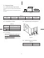
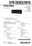
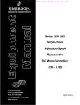
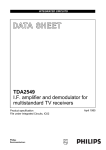
SERVICE MANUAL
AIR-CONDITIONER
SPLIT WALL TYPE
RAV-M241A-E
(Combination with RAS-13EK)
RAS-13EK
Unit B
Unit A
RAV-M241A-E
PRINTED IN JAPAN Jan, 1996
S
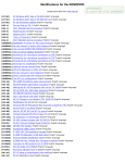
CONTENTS
1. SPECIFICATIONS ............................................................................................................. 3
2. CONSTRUCTION VIEWS ................................................................................................. 5
2-1.
Outdoor Unit ....................................................................................................................................... 5
3. WIRING DIAGRAM ........................................................................................................... 6
4. SPECIFICATIONS OF ELECTRICAL PARTS ................................................................... 7
5. REFRIGERANT PIPING DIAGRAM .................................................................................. 8
5-1.
Refrigerant Piping .............................................................................................................................. 9
6. UNIT INSTALLATION ...................................................................................................... 10
6-1.
Service Space .................................................................................................................................. 10
7. TROUBLESHOOTING CHART FOR RAS-13EK/RAV-M241A-E ..................................... 11
7-1.
7-2.
7-3.
7-4.
7-5.
7-6.
What to be Prechecked First ............................................................................................................. 11
Primary Judgement of Trouble Sources ........................................................................................... 12
Troubleshooting Flowcharts ............................................................................................................. 16
Test Points on the PC Board and List of Voltage Values .................................................................. 19
How to Check the Remote Control (Including the Indoor PC Board) ............................................... 20
PC Board Layout .............................................................................................................................. 23
8. EXPLODED VIEWS AND PARTS LIST ........................................................................... 24
–2–
1. SPECIFICATIONS
Model
RAV-M241A-E
Item
2 indoor unit
Operation
*1
Cooling capacity
*1
Power source
Power consumption
Power factor
Running current
Starting current
Operating noise (SPL*)
Refrigerant
Cooling
Cooling
Cooling
Cooling
Name of refrigerant
Charge volume
Unit
BTU/h
kcal/h
BTU/h
kW
Phase
V
Hz
kW
%
A
A
dB (A)
A
m (ft)
m (ft)
15 (48)
m (ft)
m (ft)
m (ft)
2 (7)
5 (16)
5 (16)
RAS-13EK, SERVICE DATA FILE NO. A00-9502
RAV-M241A-E
790 (2’7-7/64”)
880 (34.64”)
310 (12.2”)
70 (154.3)
Finned tube
Propeller fan
63
PH160X2-4L
1100
Fuse
Inner overload relay
kg
Refrigerant control
Interconnection pipe
Maximum height
Gas side size
Coupler style
Liquid side size
Coupler style
Standard length
Maximum length
(of one way)
Minimum length
Indoor unit higher
Outdoor unit higher
mm (in.)
mm (in.)
*2
INDOOR UNIT Model
OUTDOOR UNIT Model
Dimensions
Height
Width
Depth
Net weight
Condenser type
Condenser fan type
Fan motor output
Compressor
mm (ft-in.)
mm (ft-in.)
mm (ft-in.)
kg (lbs)
W
Model
Output
B
12000
6000
24000
7.0
1
220-240
50
2.4
97
10.8
68
53
R-22
0.85 + 0.85
Capillary tube
12.7 (1/2”)
Flare
6.4 (1/4”)
Flare
7.6 (25)
W
Protective device
*SPL: Sound Pressure Level
Specifications are subject to change without notice.
–3–
Note 1:
• Cooling capacity is based on the following temperature conditions.
27°C DB (80°F DB)
Evaporator air inlet temperature
19.5°C WB (67°F WB)
Condenser air inlet temperature
35°C DB (95°F DB)
Note 2:
•
These mean equivalent length.
Note 3:
•
Operating range of the units
Evaporator air inlet temperature
Condenser air inlet temperature
Maximum
32°C DB, 22.5°C WB
(95°F DB, 73°F WB)
43°C DB (109°F DB)
Minimum
21°C DB, 15.5°C WB
(70°F DB, 60°F WB)
21°C DB (70°F DB)
Remark:
•
Be sure to refer to the service manual file No. A00-9502 for the indoor unit RAS-13EK to be connected.
–4–
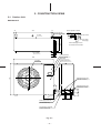
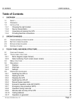
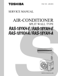
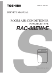
2. CONSTRUCTION VIEWS
2-1. Outdoor Unit
RAV-M241A-E
50
45
Anchor bolt hole
(4-12 X 18 long hole)
Air inlet
Space required for service
100
Space for service
100
500
790
12
45
Outlet
Air outlet
12
36
(Space for wiring
and piping)
When installing,the inlet is
to be faced to the wall side.
340
310
300
31
Electric parts box
Carrying handle
(Both side)
Electric parts cover
880
Air outlet
790
Refrigerant piping joint
(Gas side 2- Φ12.7)
70
57
Refrigerant piping joint
65
60
107 33
(Liquid side 2- Φ 6.4)
257
Power supply cord hole
(Φ19 knockout hole)
Inter-unit wiring cord hole
(Φ 28 knockout hole)
Fig. 2-1
–5–
34
86
34
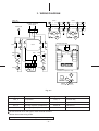
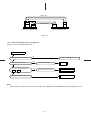
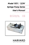
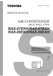
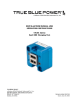
3. WIRING DIAGRAM
Unit A
Indoor Unit
Outdoor Unit
220-240V 1Ph 50Hz
power supply
Earth screw
L
N
Unit B
1
2
1
2
1
2
1
2
A 52C 1 B
20SR
A
23H1
11
13
15
52C1
11
13
12
14
A 52C 2 B
20SR
B
23H2
(Electrical Parts Box)
52C2
12
14
16
RC O
RED
RCo1
WHI
RCo
RED
RED
52C1
RCo2
WHI
52C2
RED
CM 1
BLK
RC C 1
CM 2
6 5 4 3 2 1
BLK
RC C 2
LN
1 2
1 2
6 5 4 3 2 1
51C1
51C2
BLK
FM O
Parts Position
(Fan Motor. Compressor. Coil)
BLK
CM 1
FM O
CM 2
20SRB
20SRA
Fig. 3-1
Name
Symbol
CM1, 2
FMo
RCc1, 2
RCo
Name
Symbol
Compressor
51C1, 2
Overload relay
Fan motor
52C1, 2
Magnetic contactor
Running capacitor (Compressor)
20SRA, B
Solenoid coil
23H1, 2
Thermostat
Running capacitor (Fan motor)
Shows terminal block and figures show terminal numbers.
Broken lines show wiring at site.
Don’t operate the units with the magnetic contactor pushed.
–6–
4. SPECIFICATIONS OF ELECTRICAL PARTS
Parts name
Type
Specifications
Output 1.1 kW, 2 pole, 1ø, 220-240V, 50 Hz
Compressor 1, 2
PH160X2-4L
Fan motor
STF-200-63B
Magnetic contactor
VC20FA
Solenoid coil (2-way valve)
Bimetal thermostat
Output 63W, 6 pole, 1ø, 220-240V, 50 Hz
AC 240V
MT-40MP356W
Capacitor
Winding resistance: Main coil 2.2Ω, Aux. coil 3.8Ω
EAG45M355UF1
NEV AC240
CS-12
For compressor 1, 2, AC 400V, 35 µF
For fan motor, AC 450V, 3.5 µF
AC 220-240V
110°C ON, 95°C OFF
–7–
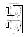
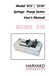
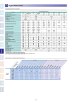
Fig. 5-1
–8–
Capillary tube
φ1.7 x 400
Dryer
Capillary tube
φ1.5 x 600
20SRA
Two way valve
Packed valve
Refrigerant pipe
(Liquld side)
φ6.4mm
Condenser
CYCLE 1
Compressor1
Accumulator
Packed valve
Capillary tube
φ1.7 x 400
Outdoor Unit
Dryer
Capillary tube
φ1.5 x 600
20SRB
Two way valve
Packed valve
Condenser
CYCLE 2
(RAS-13EK)
(RAS-13EK)
Refrigerant pipe
(Liquld side)
φ6.4mm
Evaporator
Evaporator
Refrigerant pipe
(Gas side)
φ12.7mm
(Indoor unit B)
(Indoor unit A)
Compressor2
Accumulator
Packed valve
Refrigerant pipe
(Gas slde)
φ12.7mm
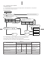
5. REFRIGERANT PIPING DIAGRAM
RAV-M241A-E
5-1. Refrigerant Piping
RAS-13EK
5-1-1. Permissible Piping Length and Head
Unit B
H
1
The minimum inter-unit refrigerant piping length shall
be 2m.
Unit A
RAS-13EK
H
2
Limit the number of bends in the refrigerant piping to
10 or less.
Fig. 5-2
Table 5-1
Model
Connectable indoor
unit number
Permissible piping
length ( 1 , 2 )
Permissible piping
head (H)
Remarks
RAS-13EK
2
15m
5m
Fig. 5-2
5-1-2. Piping Material and Sizes
5-1-4. Refrigerant Pipe Connecting Position
Table 5-2
Piping material
Phosphate deoxidized copper
seamless pipes for air conditioners
Model
RAS-13EK
Piping
size
(mm)
Larger
12.7
Smaller
6.4
5-1-3. Air Purging
•
Unit B
Subject the refrigerant tube of outdoor and indoor units to air purge with a vacuum pump.
•
Do not carry out this air purge by using the refrigerant filled in the outdoor unit.
•
To handle valves, a 5 mm hexagon wrench is
needed.
Unit A
Fig. 5-3
5-1-5. Additional Refrigerant Quantities
Table 5-2
–9–
Model
RAV-M241A-E
Addition per meter
No need
6. UNIT INSTALLATION
6-1. Service Space
Ensure that there is sufficient space around the outdoor unit for installation and servicing.
300 or more
100
or more
500 or more
500 or more
100 or more
100 or more
500 or more
Fig. 6-1
•
Do not install in a place that can increase the vibration and amplify the noise level of the units.
•
Be sure to fix the outdoor unit with four (4) M10 anchor bolts according to foundation drawings below.
45
790
15
340
364
45
Fig. 6-2
– 10 –
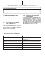
7. TROUBLESHOOTING CHART FOR RAS-13EK/RAV-M241A-E
Troubleshooting Procedures:
•
Following details of “What to be prechecked first”, make sure of the basic items.
•
When there is no trouble corresponding to above, check in detail the faulty parts following “How to judge
faulty parts by symptoms” later.
7-1-3. Operations not Regarded as Failure
7-1. What to be Prechecked First
7-1-1. Power Supply Voltage
The power supply voltage must be from AC 198V to
264V. If the power voltage is not within this range, the
air-conditioner may not work normally.
7-1-2. Incorrect Cable Connection between
Indoor and Outdoor Units.
(program operation)
In terms of the control of air-conditioner, the operations shown in Table 7-1 are made as a program operation incorporated in a microcomputer. If a claim is
made about the operation, check it corresponds to
the contents in the table. If it does, it is an indispensable operation for the control and maintenance of the
air-conditioner but not a failure of the units.
The indoor unit is connected to the outdoor unit with 3
cables. Make certain that the terminals of indoor and
outdoor connectors have been connected properly by
the same numbers. If not connected as specified, the
outdoor unit won’t operate normally.
• Operations which are not Deemed Trouble
Table 7-1
Operation of air-conditioner
Description
When the POWER plug of the indoor unit is inserted, the
OPERATION lamp flashes.
The OPERATION lamp flashes, indicating that power is
turned on. If this happens, press the START/STOP button
once, and flash will stop. Power failure also causes the
same lamp to flash.
Room temperature is in the range under which the
compressor is turned on, but the compressor will not start.
The compressor will not start while the compressor
restart prevention timer (three-minute timer) is actuated.
This applies also when power is turned on.
Fan speed remains unchanged when the fan speed button
is operated in the dry operation.
Fan speed is fixed at Low in the dry operation.
Room temperature is in the range under which the
compressor is turned off, but the compressor will not stop.
The compressor will not stop while the compressor onhold timer (two-minute timer) is actuated.
The compressor will not switch on or off even when the
thermostat control is operated in the dry operation.
In the dry operation, the compressor goes on and off at
regular intervals, independent of the thermostat control.
– 11 –
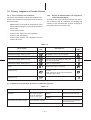
7-2. Primary Judgement of Trouble Sources
7-2-1. Role of Indoor Unit Controller
7-2-2. Display of Abnormalities and Judgement
The indoor unit controller receives the operation commands from the remote control and assumes the following functions.
of the Abnormal Spots
The indoor unit of this machine observes the operation condition of the air conditioner and displays the
contents of the self-diagnosis as block displays on
the display panel of the indoor unit.
•
Measurement of the draft air temperature of the
indoor heat exchanger by using the temperature
sensor (TA)
•
Louver motor control
•
Control of the indoor fan motor operation
•
Control of the LED display
•
Control of the outdoor unit compressor and the
outdoor fan motor.
Table 7-2
Check
code
Block display
OPERATION display flashing (1 Hz)
–
Check
code
Self-diagnosis
Power failure (When power is on)
OPERATION display flashing (5 Hz)
Temperature sensor (TA) short/break
OPERATION display flashing (5 Hz)
Heat exchanger sensor (TC) short/break
OPERATION display flashing (5 Hz)
Indoor fan lock, abnormality of indoor fan,
IC03, D15 short/break
OPERATION display flashing (5 Hz)
Indoor PC board failure
OPERATION and TIMER display flashing
(5 Hz)
• Thermal fuse is blown
(Indoor fan motor is overheat)
OPERATION, TIMER and FAN ONLY display
flashing (5 Hz)
• Gas shortage, other refrigerant cycle
trouble
• Heat exchanger sensor open/short/break
• Overload relay trouble
OPERATION, TIMER and FAN ONLY display
flashing (5 Hz)
Compressor trouble
–
(1) Judgement from defective operation or abnormal operation
Table 7-3
Check
System
No reaction on remote control
operation
The outdoor fan does not rotate
Turn off the power
once, turn it on again
and try to operate the
remote control again.
Primary judgement
Remote control is not
possible.
The indoor part (including the
remote control) is defective.
Remote control is
possible.
O.K.
The compressor operates.
The outdoor part is defective
(outdoor fan motor)
The compressor does not operate.
The inside part is defective.
– 12 –
(2) Self-diagnosis with remote controller
2) Selecting ordinary mode
With the indoor unit controller, self-diagnosis of
protective circuit action can be done by turning
the remote controller operation into service mode,
operating the remote controller, observing the remote controller indicators and checking whether
OPERATION lamp flashes (5 Hz).
Note:
•
To perform this self-diagnosis, the remote controller with the service code of 43069666 is required.
<How to select remote controller
operation mode>
1) Selecting service mode
Push the switch button provided on rear bottom of the wireless remote controller with a
tip of pencil for more than 3 seconds. Make
sure the setting temperature “ ” is displayed
on the display and other display is turned off.
Push the all clear button (ACL) on the rear
bottom of the wireless remote controller by a
tip of pencil for more than 3 seconds. Make
sure the operation mode display, wind volume
display, clock display and setting temperature
display are turned on and “ : ” of the clock
display is blinking.
<Cautions when doing service>
1) After completion of servicing, always push the
all clear (ACL) button to return the operation
mode to the normal mode.
2) After completion of servicing by the check
code, turn off the power once and then turn
on the power to reset memorized contents of
the microcomputer to the initial status.
All clear button
Switch for selecting
service mode
ACL
CLOCK
ACL CLOCK
Rear bottom cover
(Rear bottom of remote controller)
Fig. 7-1
– 13 –
<Self-diagnosis by check codes>
2) Remote control key operation under the service mode is conducted by ON/OFF or TEMP.
1) The self-diagnosis by the check codes is conducted under the block displays of item B-E.
The remote control display by each key operation is varied as shown below. Two digit
number is displayed in a hexadecimal number.
Table 7-4
Indication after operation
,,
1 is added to data before operation.
(Example)
TEMP.
(Down)
1 is subtracted from data before operation.
(Example)
,,
“AUTO” LOUVER
10 is subtracted from data before operation.
(Example)
,,
“SET” LOUVER
Data before operation is directly transferred.
(Example)
,,
,,
,,
,,
,,
3) The self-diagnosis by the check codes is conducted with procedures shown below.
a) Enter the service mode and make sure the off
timer display of the remote control shows
“ ”.
b) Operate the “ON/OFF” key and make sure the
timer lamp on the display section is blinking
(5 Hz).
c) At the same time, also make sure the OPERATION lamp is also blinking. This shows
that the protection circuit on the indoor PC
board is working.
– 14 –
,,
,,
(Up)
,,
,,
TEMP.
,,
ON/OFF
,,
Operating key
,,
,,
,,
,,
d) Operate the TEMP.
key and make sure the
remote control display shows “
” and blinking of the OPERATION lamp. If the operation
lamp is blinking, it shows the protection circuits for connecting cable is working or thermal fuse is blown.
e) In the same way, operate the TEMP. key so
that the display is increased one by one to
continue checks by the self-diagnosis as
shown is the next table. From “ ” up to “ ”
check operations of protection circuits for each
” to “ ” check operations of
block, and “
the typical protection circuits.
Table 7-5
Diagnosis function
Block level
Check
code
Block
Indoor PC
board
Cable
connection/
Thermal fuse
Check
code
Symptom
Air conditioner
status
Judgement and action
Condition
Thermo sensor
short/break.
Continued
operation
Indicated when
detected abnormal.
• Check thermo sensor.
Heat exchanger
sensor short/
break.
Continued
operation
Indicated when
detected abnormal.
• Check heat exchanger
sensor.
Indoor fan lock,
abnormality of
indoor fan.
All off.
Indicated when
detected abnormal.
• Check motor.
Abnormality of
other indoor unit
PC board.
Continued
operation
Indicated when
detected abnormal.
Replace PC board.
Wrong wiring or
disconnection of
connective cable.
All off.
Indicated when
detected abnormal.
• Check flat cable
correct if wiring is
wrong.
• If it is OK, check PC
board. (Around sensor
circuit)
• If it is OK, check PC
board. (Around sensor
circuit)
• Replace PC board, if
the same failure
occurs, after the motor
check.
• If it is OK, check PC
board.
• Thermal fuse
cut off.
All off.
• Indoor fan lock,
abnormality of
indoor fan.
Refrigerant
system
• Gas shortage.
(gas leak)
Indicated when
detected abnormal.
• Check thermal fuse.
• If it is OK, check
motor.
• If motor is OK, check
PC board.
All off.
• Other refrigerant cycle
trouble.
Indicated when
detected abnormal.
• Check gas quantity.
(Check gas leakage)
• If it is OK, check heat
exchanger sensor.
• If heat exchanger
sensor is OK, check
overload relay.
• Heat exchanger
sensor off/
break/short.
• If overload relay is OK,
check refrigerant
cycle.
• Overload relay
break
• If refrigerant cycle is
OK, check PC board.
Compressor
break down.
All off.
– 15 –
Indicated when
detected abnormal.
• Check compressor.
• If it is OK, check PC
board.
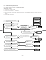
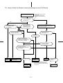
7-3. Troubleshooting Flowcharts
7-3-1. Power cannot be Turned on (No Operation at All)
<Preliminary checks>
(1) Is the supply voltage normal?
(2) Is the connection to the AC output O.K.?
(3) Are the connection of the primary side and the secondary side of the power transformer inserted into the PC
board?
(4) Is the FUSE (F01) blown?
Operations
Check items
Turn the power off for about 5 seconds
and then turn it on again.
NO
Probable main
causes
Remedies
Does the operation lamp flash?
Item by
symptons
YES
Does operation start when you press
the ON/OFF button of the remote
control?
NO
YES
Does the transmission
indicator of the remote
control blink normally,
and is the transmission
really performed?
NO
YES
Remote control
is failure.
Replace
(Normal)
YES
Is the lead wire disconnected
from the infrared rays receive parts?
Connect the
wire properly.
NO
Is 50Hz 220/230/240V AC
supplied to the primary side of the power
source transformer?
YES
Refer to above "Preliminary checks".
Or there is a defect before the power
transformer.
Infrared rays receive
parts or PC board failure.
Refer to the figure below.
Is 12V AC supplied to the secondary
side of the power transformer?
YES
NO
Replace
NO
Power transformer
is failure.
Replace
transformer.
Microcomputer is
failure.
Replace the
PC board.
Refer to the figure below.
Is the voltage display on the rear panel
of the PC board normal?
(12V DC or 5V DC)
YES
NO
12V DC, 5V DC power supply circuit failure.
(DB01, C02, Q03, D03, Q01, Q02, IC06)
Replace the
PC board.
– 16 –
Primary side
Secondary side
CN32
CN33
Transformer PC board (MCC-629)
CN06
CN05
Main PC board (MCC-639)
Fig. 7-2
7-3-2. Power Relay RY01 does not Operate.
Louver is not controlled automatically.
Turn the power ON.
Does the operation lamp flash?
NO
See "power cannot be turned on".
YES
Is the thermal fuse set on?
YES
Thermal fuse is failure.
Replace
NO
Does 12V DC supplied between
TP7 and GND ?
YES
Relay driver IC01, 02 is failure.
Replace PC board.
NO
Replace PC board.
12V power circuit failure (Q03, D03)
Note:
•
When wiring to the thermal fuse has been broken, the TIMER lamp and OPERATION lamp will flash with 5 Hz.
– 17 –
7-3-3. Only the Indoor Fan does not Operate.
<Preliminary checks>
Does it neither work in COOL or FAN ONLY operation?
< Check procedure >
Turn OFF the power.
("REMOTE CONTROL" position)
Turn ON the power.
("REMOTE CONTROL" position)
Does the fan stop at the
operation stop condition?
NO
Control PC board failure.
Replace the PC board.
YES
Start operation at HIGH cooling.
Does the fan rotate?
Does 120V AC or higher
voltage apply to between red
and black lead of the motor?
NO
YES
NO
Motor control circuit failure (IC01,
03, D15) or 12V power circuit (Q03,
D03) or thermal fuse failure.
YES
Turn OFF the power.
Is it possible to rotate the
cross flow fan by hand?
Change the setting to LOW cooling.
NO
Repair the cross flow fan.
YES
Turn ON the power.
Does the rotating speed
of the fan lower?
YES
NO
Stop the
operation
When rotating the cross flow fan by
hand at the operation stop condition,
is the rotation signal (+12VDC
0V)
detected between 2 (gray lead) and
3 (brown lead) of the motor
connector (PJ13 or CN13)?
(1pulse/1 revolution)
NO
Replace the fan motor.
YES
Normal
Motor circuit (D06, IC01) or 12V
power circuit (Q03, D03) failure.
– 18 –
Replace the control PC board.
7-3-4. Compressor does not Operate.
< Preliminary checks >
(1) Is the temperature set on the remote control higher than the room temperature in cool operation?
(2) Is contact of the crossing wiring O.K.?
< Check procedure >
Turn the power ON.
NO
Does the operation lamp flash?
Refer to "Power cannot be turned on".
YES
NO
Does power relay RY01 switch due
to temperature adjustment?
Point for placing the tester bar
Polarity : +
IC02, 9 pin
YES
Polarity : -
Condition
IC02, 14 pin
RY01 ON
Normal voltage
value
Is the resistance value of the thermo
sensor (TA) and heat exchanger sensor
(TC) normal?
DC 12V
Approximate resistance value of the sensor
Normal voltage value under
power relay ON condition.
10 C
20 C
20.7k Ω
12.6k Ω
NO
30 C
7.97k Ω
YES
Thermo sensor or heat exchanger
sensor is failure.
NO
Is 220/ 230/ 240V AC
supplied between terminal blocks 1 and 2 ?
Replace thermo
sensor or heat
exchanger sensor.
YES
Microcomputer
is failure.
Replace
PC board.
Power relay RY01
is failure.
Outdoor unit is
failure.
Replace
power relay.
7-4. Test Points on the PC Board and List of Voltage Values
The test points (TP) are indicated on the rear of the PC board.
The voltage values on the test points for defect diagnosis items are listed below.
Table 7-6
Point for placing the tester bar
Defect diagnosis item
Normal voltage value
Polarity (+)
Polarity (–)
Condition
Does the power relay (RY01) switch?
IC02, 9 pin
IC02, 14 pin
When relay
RY01 is ON.
Is the voltage of the secondary side of
the transformer O.K.?
TP3
TP4
–
No load:
14 ± 2V
With load: 12 ± 2V
(Primary voltage is
about 230V)
Is the voltage of the primary side of
the transformer O.K.?
TP1
TP2
–
220-240V AC
–
5V AC or less: normal
5V AC or more: abnormal
Are both PTH terminals 5V AC or less?
Either end of PTH
– 19 –
12V DC
(When relay is ON.)
7-5. How to Check the Remote Control (Including the Indoor PC Board)
Push the START/STOP button
There is no reception tone from
the receptor.
The operation lamp of the air
conditioner main unit does not
light.
NO
Does the transmission
indicator flash?
YES
Is there direct sunlight
on the receptor of the
air conditioner?
NO
NO
YES
Is operation possible
when the transmitter is
moved nearer to the
infrared signal receiver
of the air conditioner?
Push the all clear button (ACL) on the
wireless remote control with a tip of pencil
for more than 3 seconds.
YES
Is there any thyristor
fluorescent light near by?
NO
Does the transmission
indicator light?
YES
YES
Battery life
Is operation possible when
setting the control operation
switch of the air conditioner main
unit to "COOL" or "AUTO"?
NO
NO
NO
YES
Can any signal tone be heard in
a transistor radio when
transmitting within 5cm distance
from the radio?
Is there any reception
tone and operation?
YES
NO
YES
Avoid direct
sunlight.
Keep the air conditioner
away from thyrstor
fluorescent light.
PC board is failure.
Replace the
batteries.
Note:
Replace
PC board.
– 20 –
Normal
After battery replacement, shortcircuit
the metal terminal at the side of the
battery compartment (all-clear terminal)
with a pencil.
Remote control
is failure.
Replace
remote control
7-5-1. How to Check the PC Board
(1) Operating precautions
2) The PC board consists of the following 4 parts:
a. Main PC board part:
1) When removing the front panel or the PC
board, be sure to disconnect the power plug
from the AC outlet.
Power relay, indoor fan motor drive circuit and
control circuit, C.P.U. and peripheral circuits,
buzzer drive circuit and buzzer.
2) When removing the PC board, hold the edge
of the PC board and do not apply force to the
parts.
b. Infrared rays receive parts:
Infrared rays receiving circuit
c. Display:
3) When connecting or disconnecting the connectors on the PC board, hold the whole housing. Do not pull at the lead wire.
LED
d. Switch PC board:
Wireless-control, TEMPORARY switch
e. Buzzer PC board:
(2) Inspection procedures
1) When a PC board is judged to be failure, check
for disconnection, burning, or discoloration of
the copper foil pattern or this PC board.
Buzzer
f. Transformer PC board:
Transformer
Check the defects of the PC board following the
list below.
(3) Checking procedure
Table 7-7
Procedure
• Disconnect the power plug from the
AC outlet and remove the PC board
assembly from the electronic parts
base.
Check point (Symptom)
Is the fuse blown?
Trouble cause
• Application of shock voltage
• Short-circuit of the indoor fan
motor
• Remove the flat cable from the
terminal plate.
• Turn the power ON.
Check power supply voltage.
• If the OPERATION lamp flash (0.5
sec. ON, 0.5 sec. OFF), steps 1 – 3
in the right column are not necessary.
1.Between pins 1 and 3 of CN05
(220 – 240V AC)
• Defective power cord, power
switch, fuse or line filter, or wrong
wiring
2.Between pins 1 and 3 of CN06
(12V AC)
• Defective power transformer
3.Between TP6 (+5V) and GND
(5V AC)
• Defective power circuit or shortcircuited load
4.Between TP7 (+12V) and GND
(12V DC)
• Same as above
5.Between TP8 (+12V) and GND
(12V DC)
• Thermal fuse operation
Push the START/STOP button once to
set in operation mode.
(Do not set to the fan only or on-timer
mode.)
Start operation by using the antirestart timer.
Check power supply voltage.
1.Power relay coil voltage (12V DC)
IC02, 9 pin and IC02, 14 pin
• Relay coil cable is broken, relay
driver (IC181) is defective.
2.Between terminals 1 and 2
• Relay contact is defective, SL
connector is defective.
1.All LEDs of the OPERATION lamp,
the TIMER lamp, FAN ONLY lamp,
ECONO. and AUTO lamp light up.
• Display is failure or defect in the
9P housing assembly.
2.After 3 seconds, normal display
does not appear.
– 21 –
Procedure
Trouble cause
Check point (Symptom)
Push the START/STOP button once to
set in operation mode.
1. The compressor does not operate.
• The temperature of the indoor
heat exchange unit is extremely
low.
2. The OPERATION lamp flashes.
• Defective control PC board.
Connect the motor connector to
“MOTOR” and turn the power ON.
Start operation as follows:
1. There is a voltage of 120V or more
between the red and black motor
connector leads.
• Indoor fan motor is failure.
1.Set the operation mode to “FAN
ONLY”.
2. The motor does not rotate. (But the
key operation of the remote control
is accepted.)
• Contact of the motor connector is
defective.
3. Motor rotates but vibrates hard.
• Main PC board is failure.
1.Setting the anti-restart timer
2.Cooling operation
3.Fan speed: AUTO
4.Set the temperature sufficiently
lower than the room temperature.
5.Continuous operation
2.Set the fan speed to “HIGH”.
3.Continuous operation
Table 7-8 Approximate value of the sensor (thermistor) resistance (TA, TC)
Sensor
Temperature
Thermo Sensor
0°C
10°C
20°C
25°C
30°C
35.8
20.7
12.6
10.0
7.92
(= kΩ)
7-5-2. How to Reduce the Operation Time of the Anti-restart Timer
•
Drill 2 holes on the rear of the wireless remote
control unit.
Wireless remote controller
Attach the diode (1S1555 or equivalent) to the
rivet inside the unit.
•
Push the START/STOP button to start operation
with the diode attached.
Timer short diode
Fig. 7-3
– 22 –
7-6. PC Board Layout
Top view
Bottom view
– 23 –
8. EXPLODED VIEWS AND PARTS LIST
01
12
10
22
03
02
24
13
25
26
29
21
19
30
03
23
Location
No.
Part
No.
01
02
03
43120168
43143701
43041728
10
12
13
19
Description
Fan, Propeller
Condenser
Compressor, AC 220/240V,
50 Hz, PH160X2-4L
43121636 Motor, Fan, STF-200-63B
43191494 Guard, Fan
43046151 Valve, 2 Way
43046232 Packed Valve, 12.7
– 24 –
Location
No.
Part
No.
21
22
23
24
25
26
29
30
43046228
43145103
43119390
43146443
43047492
43047491
43049625
43066988
Description
Packed Valve, 6.35
Dryer
Hanger
Solenoid Coil
Capillary Tube, 1.7 Dia
Capillary Tube, 1.5 Dia
Cushion, Rubber
Holder, OL-Relay
05
08
18
05
08
RCo
52C1
52C2
RCc1
06
RCc2
07
L N
1 2
1 2
14
24
14
Location
No.
05
06
07
08
Part
No.
43154139
43160479
43160480
43055354
32
Location
No.
Description
Switch, Magnet
Terminal, Block, 2P
Terminal, Block, 6P
Capacitor, Plastic Film,
35MFD, 400V
14
18
24
32
– 25 –
Part
No.
43054380
43155146
43146443
43150220
Description
Relay, Overload
Capacitor, Electrolytic
Solenoid Coil
Bimetal Thermostat
MEMO
– 26 –
MEMO
– 27 –
TOSHIBA CORPORATION
1–1, SHIBAURA 1– CHOME, MINATO – KU, TOKYO 105 – 01, JAPAN