1
Matsushita Electric Works Fire & Security Technology AB
Operating Instructions
MEW00228
Revision 2
Fire Alarm System EBL512
V2.1.x
Author:
Jan Pettersson
Date of issue: 2002-02-25
Date of rev:
2002-12-16
This page has deliberately been left blank.
Matsushita Electric Works Fire & Security Technology AB
MEW00228
Rev: 2
EBL512 Operating Instructions V2.1.x
Table of contents
1
2
Introduction________________________________ 7
Definitions / Explanations ____________________ 8
2.1
2.2
MFSTech_________________________________________ 8
Alarm points ______________________________________ 8
2.2.1
Smoke detector _______________________________ 8
2.2.2
Sensor ______________________________________ 8
2.2.3
Analog detector _______________________________ 8
2.2.4
(Analog) Sensor Base (ASB)_____________________ 8
2.2.5
Conventional detector __________________________ 8
2.2.6
Conventional Detector Base (CDB) _______________ 8
2.2.7
Addressable Detector Base (ADB) ________________ 8
2.2.8
Addressable __________________________________ 9
2.2.9
Old detector __________________________________ 9
2.2.10
External line / Conventional zone line _____________ 9
2.2.11
ADB input / Addressable zone interface ____________ 9
2.3
Output unit _______________________________________ 9
2.4
Output / Control output ______________________________ 9
2.5
Short circuit isolator ________________________________ 9
2.6
Display unit _______________________________________ 9
2.7
COM loop ________________________________________ 9
2.8
BS4 loop _________________________________________ 9
2.9
Control Unit (C.U.) / C.I.E.__________________________ 10
2.10 Fire Brigade Panel (FBP) ___________________________ 10
2.11 Control panel (CP) ________________________________ 10
2.12 System __________________________________________ 10
2.13 Network / TLON® / LonWorks® / Echelon / Node / TLON
Conn. board / Gateway / Channel / Router / Repeater ___________ 10
2.14 LED ____________________________________________ 11
2.15 External Indicator (LED) ___________________________ 11
2.16 Display / LCD ____________________________________ 11
2.17 Door open / Key switch_____________________________ 11
2.18 SSD / Site Specific Data ____________________________ 11
2.19 SW / Software / System program _____________________ 11
3
Overview _________________________________ 12
3.1
The EBL512 system _______________________________ 12
3.1.1
Expansion boards ____________________________ 12
3.1.2
Printer _____________________________________ 12
3.2
SW versions _____________________________________ 12
3.3
Documents_______________________________________ 13
3.4
Applications _____________________________________ 13
3.5
PC SW__________________________________________ 13
4
Control Unit ______________________________ 14
1
Matsushita Electric Works Fire & Security Technology AB
MEW00228
Rev: 2
EBL512 Operating Instructions V2.1.x
5
6
LED indicators and push buttons _____________ 16
Normal operation __________________________ 20
6.1
Alphanumeric display in the control unit _______________ 20
7
Access levels_______________________________ 21
7.1
7.2
7.3
7.4
7.5
7.6
Access level 0 ____________________________________ 21
Access level 1 ____________________________________ 21
Access level 2 ____________________________________ 22
Access level 3 ____________________________________ 23
Access level 4 ____________________________________ 24
Access level 5 ____________________________________ 24
8
"Silence Alarm devices" ____________________ 25
8.1
8.2
8.3
Silence before a fire alarm __________________________ 25
Silence during a fire alarm __________________________ 25
Alarm device on / Alarm device off ___________________ 25
9
10
11
12
"Silence buzzer" ___________________________
Controls ON / Controls OFF _________________
Evacuate__________________________________
Door open ________________________________
12.1
12.2
LED "Door open" _________________________________ 29
Outputs for routing equipment (Fire brigade tx and Fault tx) 29
13
Technical number / Presentation number ______ 30
13.1
13.2
13.3
Technical number for COM loop units _________________ 30
Technical number for BS4 loop units __________________ 31
Presentation number _______________________________ 32
14
Alarm types _______________________________ 33
26
27
28
29
14.1 Pre-warning ______________________________________ 33
14.2 Fire alarm _______________________________________ 34
14.2.1
Fire alarm menu______________________________ 35
14.2.2
Alert annunciation ____________________________ 37
14.2.3
2-zone / address dependence (co-incidence alarm) ___ 38
14.3 Heavy smoke alarm / Heavy heat alarm ________________ 38
14.4 Key cabinet alarm _________________________________ 39
14.4.1
Key cabinet opened before a fire alarm____________ 39
14.4.2
Key cabinet opened in conjunction with a fire alarm _ 39
14.4.3
Key cabinet alarm, DBI convention ______________ 40
15
Alarm reset _______________________________ 41
15.1 Pre-warning reset _________________________________ 41
15.2 Fire alarm reset ___________________________________ 41
15.2.1
Multiple reset________________________________ 41
15.2.2
Single reset _________________________________ 41
15.2.3
Single encapsulated reset (Zone/Detector not reset) __ 42
15.2.4
Alert annunciation ____________________________ 42
15.2.5
Co-incidence alarm ___________________________ 42
2
Matsushita Electric Works Fire & Security Technology AB
MEW00228
Rev: 2
EBL512 Operating Instructions V2.1.x
15.3
15.4
Heavy smoke / heat alarm reset_______________________ 43
Key cabinet alarm reset _____________________________ 43
16
Fault _____________________________________ 44
16.1
16.2
Fault messages ___________________________________ 45
Fault acknowledge ________________________________ 56
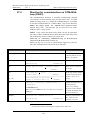
17
Commissioning an installation _______________ 57
17.1 Single Control Unit ________________________________ 57
17.2 Control Units in a TLON network ____________________ 57
17.2.1
TLON network programming (configuration) ______ 58
18
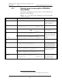
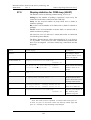
Programming (SSD download) _______________ 59
18.1 Check All Loop Units ______________________________ 59
18.2 Single Control Unit ________________________________ 59
18.3 Control Units in a TLON network ____________________ 60
18.4 User definable text messages download ________________ 60
18.4.1
Download in Control unit ______________________ 61
18.4.2
Download in Display unit ______________________ 61
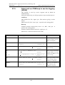
19
New system program (SW) version download ___ 62
19.1
19.2
A single control unit (c.i.e.) _________________________ 62
Control Units in a TLON network ____________________ 63
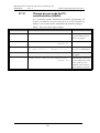
20
EBL512 settings download___________________ 64
20.1
Control Units in a TLON network ____________________ 64
21
Reset / Restart _____________________________ 65
21.1
Boot menu _______________________________________ 67
22
23
24
Access ____________________________________ 68
Perform monthly test (H1)___________________ 69
Disable or re-enable (H2) ____________________ 71
24.1
24.2
24.3
24.4
24.5
24.6
24.7
24.8
24.9
Disable zone (H2/B1) ______________________________ 72
Disable zone / address (H2/B2)_______________________ 73
Disable control output (H2/B3)_______________________ 74
Re-enable zone (H2/B4) ____________________________ 75
Re-enable zone / address (H2/B5)_____________________ 76
Re-enable control output (H2/B6)_____________________ 77
Re-enable non-reset zone / address (H2/B7)_____________ 78
Control on / Control off (H2/B8) _____________________ 79
Alarm devices on / Alarm devices off (H2/B9) __________ 80
25
26
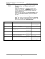
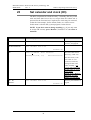
Set calendar and clock (H3) __________________ 81
Present system status on display and printer (H4) 82
26.1 Disablement (H4/U1) ______________________________ 82
26.2 Disablement by time channel (H4/U2) _________________ 83
26.3 Doors open (H4/U3) _______________________________ 84
26.4 Activated 2-zone/address dependent zone/address (H4/U4)_ 85
26.5 Sensor values (H4/U5) _____________________________ 86
26.5.1
Reset of a week average sensor value _____________ 88
3
Matsushita Electric Works Fire & Security Technology AB
MEW00228
Rev: 2
EBL512 Operating Instructions V2.1.x
26.5.2
Algorithm setting via menu H4/U5 _______________ 89
26.6 Sensors activating SERVICE signal (H4/U6) ____________ 94
26.7 Event log (H4/U7)_________________________________ 95
26.8 Configuration (H4/U8) _____________________________ 96
27
Service (H5) _______________________________ 97
27.1
27.2
27.3
27.4
27.5
27.6
27.7
27.8
27.9
27.10
27.11
Access code for service (H5) ________________________ 98
Calibration of supervised outputs (H5/A1) ______________ 99
Sensitive fault detection mode (H5/A2) _______________ 100
Direction for communication on COM-/BS4-loop (H5/A3) 101
Show information about Site Specific Data (H5/A4) _____ 102
Display current consumption in unit (H5/A5)___________ 103
Display current consumption COM-/BS4-loop (H5/A6) __ 104
Display statistics for COM-loop (H5/A7)______________ 105
Select unit on COM-loop to use for trigging (H5/A8) ____ 106
Change access code for PC-communication (H5/A9) __ 107
Change access code for service (H5/A10) ___________ 108
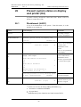
28
29
30
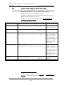
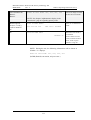
Acknowledge FAULTS (H6) ________________ 109
Perform ZONE TEST (test mode) (H7) _______ 110
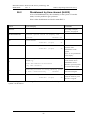
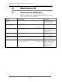
Maintenance (H8) _________________________ 112
30.1
30.2
30.3
30.4
30.5
30.6
30.7
30.8
30.9
30.10
Access code for maintenance _______________________ 112
Disable or re-enable outputs for routing equipment (H8/S1)113
Disconnect loop (H8/S2)___________________________ 114
Re-connect loop (H8/S3)___________________________ 115
Acknowledge SERVICE signal (H8/S4)_______________ 116
Clear weekly average (H8/S5) ______________________ 117
Safe shut down of control unit (H8/S6) _______________ 118
Activate address in alarm mode (H8/S7) ______________ 119
Synchronize the control units (H8/S8) ________________ 121
Change access code for maintenance (H8/S9)________ 122
31
Interlocking outputs and inputs (H9) _________ 123
31.1
31.2
31.3
31.4
31.5
Activated interlocking outputs/inputs (H9/C1) __________ 123
Activate interlocking output (H9/C2) _________________ 124
Reset interlocking output (H9/C3) ___________________ 125
Disable interlocking output (H9/C4)__________________ 126
Re-enable interlocking output (H9/C5)________________ 127
32
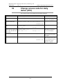
Change access code for daily duties (H10) _____ 128
33
Annual control ___________________________ 129
34
How to change paper in the printer __________ 130
35
Replacing a TLON connection board and/or a main
board 131
36
Battery maintenance_______________________ 132
37
How to avoid unnecessary (nuisance) fire alarms133
4
Matsushita Electric Works Fire & Security Technology AB
MEW00228
Rev: 2
38
39
EBL512 Operating Instructions V2.1.x
Information regarding radioactive radiation source135
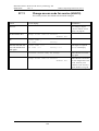
Revision history___________________________ 136
5
Matsushita Electric Works Fire & Security Technology AB
MEW00228
Rev: 2
6
EBL512 Operating Instructions V2.1.x
Matsushita Electric Works Fire & Security Technology AB
MEW00228
Rev: 2
1
EBL512 Operating Instructions V2.1.x
Introduction
EBL512 Operating Instructions is a document1 intended to be used by
the end user and the fire brigade personnel as well as service /
commissioning engineers.
Due to continual development and improvement, different SW
versions are to be found. This document is valid for SW version
2.1.x. On the date of revision 2 is x=3.
Since the EBL512 control unit (c.i.e.) is produced for many countries
the look, the texts, the functions, etc. may vary.
Products
Consists of one or more parts (HW) according to a Product Parts
List. A product has:
•
a type number (e.g. 1548)
•
an article number, often = the type no. and sometimes is a
country code added (e.g. 1548SE)
•
a product name (e.g. EBL512 control unit, 128 addresses,
without printer)
HW
A HW (e.g. a printed circuit board) has:
•
a type number (e.g. 1556)
•
an article number, often = the type no. and sometimes is a
country code added (e.g. 1556SE)
•
a product name (e.g. Main Board 128 addr.)
•
a p.c.b. number (e.g. 9261-3A) and can also have a configuration
(e.g. CFG: 1) and a revision (e.g. REV: 2)
•
sometimes a SW
SW
A SW has:
•
a version number (e.g. V2.1.1)
•
sometimes additional information, such as Convention (different
functions / facilities), Language, Number of addresses, etc.
PC SW
A PC SW is a program used for programming, commissioning, etc. It
has a version number.
1
File name: K:\PRO\FIRE\512\Doc\2.1x\MEW00228.doc
7
Matsushita Electric Works Fire & Security Technology AB
MEW00228
Rev: 2
2
EBL512 Operating Instructions V2.1.x
Definitions / Explanations
Definitions / explanations / abbreviations / etc. frequently used or not
explained elsewhere in the document.
2.1
MFSTech
Matsushita Electric Works Fire & Security Technology AB
2.2
Alarm points
Units, which can generate fire alarm (in the control unit), i.e. a sensor,
a conventional detector, a manual call point, etc.
2.2.1
Smoke detector
Two types of analog and conventional smoke detectors are available:
photo electric (optical) and ionization.
2.2.2
Sensor
Sensor = Analog detector
2.2.3
Analog detector
Contains an A/D-converter. The Control Unit pick up the digital
values ("sensor values") for each detector individually.
All
evaluations and "decisions" are then made in the C.U. Analog
detectors are addressable – an address setting tool is used for detector
types 33xx and a DIL-switch in the ASB (see below) for detectors
2xxx. An analog detector has to be plugged in an ASB.
2.2.4
(Analog) Sensor Base (ASB)
A sensor is plugged in an ASB, which is connected to a COM loop
(see below). Sensor Base types 2xxx have a DIL-switch for COM
loop address setting.
2.2.5
Conventional detector
Detector with two states, normal or fire alarm. The detector contains a
closing contact and a series alarm resistor. Some types are plugged in
an ADB (see below) or a CDB (see below). Some types are also
available as addressable, to be connected to a COM loop (see below).
(Normally plugged in a CDB (see below), connected to a conventional
zone line with end-of-line resistor.)
2.2.6
Conventional Detector Base (CDB)
A conventional detector is plugged in a CDB, connected to an external
line, an addressable zone interface, conventional zone line, etc.
2.2.7
Addressable Detector Base (ADB)
A conventional detector is plugged in an ADB, connected to a COM
loop (see below).
8
Matsushita Electric Works Fire & Security Technology AB
MEW00228
Rev: 2
2.2.8
EBL512 Operating Instructions V2.1.x
Addressable
A unit with a built-in address device, i.e. each unit is individually
identified, handled and indicated in the control unit.
(The unit can consequently be an addressable zone interface, to which
one or more conventional "alarm points" can be connected.).
2.2.9
Old detector
Conventional detector with a closing contact (short circuit; no alarm
resistor), or detector with two breaking contacts.
2.2.10
External line / Conventional zone line
Input (to an ADB / an addressable zone interface or expansion board),
intended for one or more conventional alarm points. End-of-line
resistor in the last alarm point.
2.2.11
ADB input / Addressable zone interface
Unit with an input (ext. line / conventional zone line) intended for one
or more conventional alarm points. End-of-line resistor in the last
alarm point.
2.3
Output unit
Addressable unit with programmable control outputs.
connected to a COM loop (see below).
2.4
To be
Output / Control output
Defined or programmable function. Relay or (supervised / monitored)
voltage output, in the C.U. or an output unit.
2.5
Short circuit isolator
Addressable unit for automatic disconnection of a part of a COM loop
(see below) in case of a short circuit on the loop.
2.6
Display unit
Addressable unit for fire alarm presentation (incl. user definable text
messages, if programmed). Connected to a COM loop (see below).
2.7
COM loop
Loop = a cable, with two wires, to which all the addressable MFSTech
units can be connected. It starts in the C.U. and it returns back to the
C.U.
2.8
BS4 loop
Loop = a cable, with two wires, to which all the addressable Autronica
(BS100) units can be connected. It starts in the C.U. (EBL512) and it
returns back to the C.U.
9
Matsushita Electric Works Fire & Security Technology AB
MEW00228
Rev: 2
2.9
EBL512 Operating Instructions V2.1.x
Control Unit (C.U.) / C.I.E.
Control Unit = C.U. = Control and Indicating Equipment = Unit to
which the alarm points are connected, e.g. EBL512. Indicates fire
alarm, fault condition, etc. Fire Brigade Panel & Control Panel (see
below) included or not included. Printer included or not included.
2.10
Fire Brigade Panel (FBP)
Unit intended for fire alarm presentation, etc. for the fire brigade
personnel. Can be a part of the control unit (front) or a separate unit;
an external FBP.
In the ext. FBP a printer can be included or not included.
2.11
Control panel (CP)
A part of the control unit (front ), intended for the building occupier,
service personnel, etc., to "communicate" with the control unit /
system.
2.12
System
Several control units connected via a TLON network (co-operating
control units).
2.13
Network / TLON® / LonWorks® / Echelon /
Node / TLON Conn. board / Gateway /
Channel / Router / Repeater
Brief explanations to the words/expressions to be found in connection
with a "network". See also separate TLON Technical description.
TLON® = TeleLarm Local Operating Network = a LonWorks®- based
network2 for communication between several control units (nodes).
The protocol is LonTalk and the transmission works with doublyterminated bus topology (Echelon FTT-10). To connect a control unit
to the network, a TLON connection board is plugged in the control
unit. (Some old types of control units, not prepared for network
connection, have to be connected via a serial interface and a
Gateway).
A network can be one channel (FTT-10) or several channels,
connected via routers or repeaters.
Repeaters are used to increase the maximum cable length, C.U. to
C.U. in a network.
2
LonWorks® = A "summing-up-name" for the market of Echelon
Corporation Inc. technology.
10
Matsushita Electric Works Fire & Security Technology AB
MEW00228
Rev: 2
EBL512 Operating Instructions V2.1.x
Router or Repeater is the same type of unit (different configuration).
All network programming (configuration) are made with the PC
program "TLON Manager".
2.14
LED
LED (Light Emitting Diode) = Yellow, green or red optical indicator
("lamp").
2.15
External Indicator (LED)
A unit with an LED. Connected to an ASB, ADB, CDB or a detector
with a built-in LED. Lit when the built-in LED is lit.
2.16
Display / LCD
LCD (Liquid Crystal Display) = Display for presentation of fire
alarms, fault messages, etc. Normally alphanumeric characters and
backlight.
2.17
Door open / Key switch
In most EBL512 configurations there is a door switch which is
activated when the control unit door is opened.
In some
configurations does a key switch replace this door switch.
The LED "Key switch" is indicating "door open" / key switch in
position "access".
2.18
SSD / Site Specific Data
This data is unique for each installation.
All alarm points,
presentation numbers, user definable text messages, programmable
outputs, etc. are programmed (configured) in the PC program Win512
and has to be downloaded in EBL512.
2.19
SW / Software / System program
The SW makes the control unit (the microprocessor) work. It is
factory downloaded but a new version can be downloaded in EBL512
on site.
11
Matsushita Electric Works Fire & Security Technology AB
MEW00228
Rev: 2
3
Overview
3.1
The EBL512 system
EBL512 Operating Instructions V2.1.x
EBL512 is a microprocessor controlled intelligent fire alarm system,
intended for analog addressable smoke detectors, as well as
conventional detectors and manual call points. Programmable control
outputs and output units are available. Up to 512 addresses can be
connected to each control unit (c.i.e.).
EBL512 is available in several types, versions and configurations. It
can be connected to a TLON network, a "system", with up to 30
independent control units. Each control unit has total access to all
information.
EBL512 is designed according to the European standard EN54, part 2
and 4.
3.1.1
Expansion boards
In the control unit (c.i.e.) it is possible to mount up to six expansion
boards. The following types are available:
1580 8 zones expansion board
1581 8 relays expansion board
1582 External FBP interface board3
1583 German FBP interface board4
1584 Autronica interface board (four BS4 loops)5
Regarding the expansion boards, see also the EBL512 Planning
Instructions and drawings.
3.1.2
Printer
Control unit 1549 is equipped with a printer.
In control unit 1548 it is possible to mount a 1558 Printer.
3.2
SW versions
Due to continual development and improvement, different SW
versions can be found. When installing a new control unit in a system
with "older" control units, you may have to update the SW in the old
control units. It is highly recommended to have the same SW
version in all control units but the SW version 2.X.x require the
same SW version in all control units.
3
Max. two 1582 boards per control unit.
4
Max. one 1583 board per control unit. 1583 board is not possible to use in
Swedish (SBF) convention.
5
Max. four 1584 boards per control unit. 1584 board is only possible to use
in Swedish (SBF) convention.
12
Matsushita Electric Works Fire & Security Technology AB
MEW00228
Rev: 2
3.3
EBL512 Operating Instructions V2.1.x
Documents
The following documents are available:
• Planning instructions
• Drawings
• Operating instructions
Normally information that is found in one document is not to be found
in another document, i.e. the documents complement each other.
3.4
Applications
The EBL512 system is intended for small, medium and large
installations. The intelligent control units offer the system designer
and end user a technically sophisticated range of facilities and
functions. Programming (PC SW Win512) and commissioning of the
control unit / system is very easy. Start with one control unit and then,
when required, add more units. The TLON network makes it possible
to install the control units in one building or in many buildings.
3.5
PC SW
Win512 is used for programming and commissioning of one or more
control units:
•
download / backup of site specific data (SSD)
•
download of SW / settings / conventions / configurations / C.U. &
system data / etc.
•
create and download the user definable text messages shown in
the alphanumeric display in the C.U. / ext. FBP and in the Display
units.
Win512 shall have the same (or higher) version number as the
EBL512 SW version number (e.g. 2.1). Backup require the same
version number (in Win512 and EBL512). Old files can be opened
and saved in a higher version of Win512 and thereafter downloaded.
TLON Manager is used for programming of network data / addresses
/ etc.
NEWTEXT (DOS based "older" program) can be used to create /
download the user definable text messages in the Display units
connected to the COM loops.
13
Matsushita Electric Works Fire & Security Technology AB
MEW00228
Rev: 2
4
EBL512 Operating Instructions V2.1.x
Control Unit
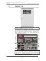
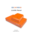
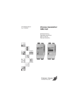
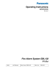
Figure 1. The EBL512 Control Unit (1548 / 1549). The look
may vary according to configuration, country, etc.
The control unit (c.i.e.) is housed in a grey metal cabinet. The door
has a Plexiglas ahead of the FBP part, see Figure 1. When the door is
open, you fully see the front (the Fire Brigade Panel, FBP, and
Control Panel, CP), see Figure 2.
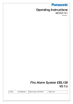
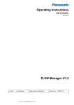
Figure 2. The EBL512 front; FBP (upper black part) and CP
(lower grey part). The look may vary according to configuration,
convention, etc. (English config. in figure). See also chapt.
"LED indicators and push buttons", page 16.
14
Matsushita Electric Works Fire & Security Technology AB
MEW00228
Rev: 2
EBL512 Operating Instructions V2.1.x
The fire brigade personnel use the FBP to see which alarm point /
zone(s) having generated fire alarm. In the alphanumeric display
(LCD, 2x40 alphanumeric characters), the information displayed on
the first row is depending on how many alarm points / zones having
generated fire alarm (and also convention). On the second row is, for
an alarm point or a zone, a user definable text message shown, if
programmed.
Required fire brigade personnel manoeuvres can be performed from
the FBP.
The CP is used to "communicate" with the system, e.g. for
commissioning, monthly tests or maintenance. Access codes for
different access levels are required. A keypad is used to get access to
the system (a menu tree with main and sub menus) and for different
manoeuvres. The CP has several system status LEDs.
15
Matsushita Electric Works Fire & Security Technology AB
MEW00228
Rev: 2
5
EBL512 Operating Instructions V2.1.x
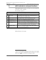
LED indicators and push buttons
LEDs and push buttons can vary according to type and configuration
(convention / country / language).
See also Figure 2, page 14.
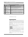
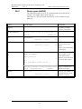
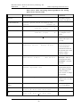
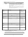
LED indicators on the Fire Brigade Panel (FBP)
LED indicator
Indicating
L1
Fire (5 red)
Fire alarm (also pre-warning, heavy smoke/heat alarm, key
cabinet alarm & co-incidence alarm)
L2
Alarms queued (2 red)
More than one unit / zone have generated fire alarm.
L3
Extinguishing (red)
Output(s) for extinguishing equipment activated.6
L4
Ventilation (yellow)
Output(s) for fire/smoke ventilation equipment activated.6
L5
Fire brigade tx (red)
Output(s) for fire brigade tx (routing equipment) activated.6
Test of routing equipment in progress (see menu H1).
L6
Operation (green)
Power on, i.e. the power supply (rectifier and/or battery are
connected and working properly.
(FBP push buttons on next page)
6
L3-L5 can be individually programmed to indicate when its normal trigger
condition is met or when a programmable input is activated (e.g. L5 can be
turned on when an input is activated by a Fire brigade tx output.
16
Matsushita Electric Works Fire & Security Technology AB
MEW00228
Rev: 2
EBL512 Operating Instructions V2.1.x
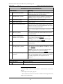
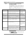
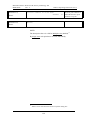
Push buttons on the Fire Brigade Panel (FBP)
Push button
Operation/function
P1
Alarms queued (black)
Used, when LEDs "Alarms queued" (L2) are lit, to
scroll/browse through the queued alarms (zones).
P2
Silence buzzer
(yellow)
Used to silence the buzzer in the c.i.e.
P3
Silence Alarm devices
(red)
Used to silence the sounders (i.e. to "reset" outputs for alarm
devices).
P4
Reset (green)
Used to reset the fire alarm(s).7 Has to be pressed for > 0.5
sec.
P5
Evacuate (green) 8
Used to activate the sounders (i.e. the outputs for alarm
devices).
(CP LED indicators on next page)
7
Multiple reset (Default): All fire alarms in the system will be reset
simultaneously. Single reset: The fire alarm displayed in the LCD (first row
to the left) will be reset. When more than one fire alarm is generated (LEDs
"Alarms queued" are lit) each fire alarm has to be individually reset. Single
encapsulated reset: Fire alarm reset like "Single reset". Encapsulation
function described in EBL512 Planning Instructions, chapter "System
properties (settings).
NOTE (1)! When "Multi reset" or "Single reset" is used, encapsulated reset
can be done by pressing "Reset" (P4) and 0.1 sec. later also press "Alarms
queued" (P1) and hold them pressed for > 0.5 sec.
By Single reset: The fire alarm displayed in the LCD (first row to the left)
will be encapsulated.
By Multiple reset: The fire alarm displayed in the LCD (first row to the left)
will be encapsulated or the points in alarm status within one zone will be
encapsulated or the whole zone (conventional) will be encapsulated.
NOTE (2)! When "Single reset" or "Single encapsulated reset" is used, you
can make a "Multiple reset" by pressing "Reset" (P4) and 0.1 sec. later also
press "A" (in the keypad) and hold them pressed for > 0.5 sec.
8
"Evacuate" is only valid in the "British Standard" convention. In "Polish"
(CNBOP) convention, this button is used for "Alert annunciation
Acknowledge".
17
Matsushita Electric Works Fire & Security Technology AB
MEW00228
Rev: 2
EBL512 Operating Instructions V2.1.x
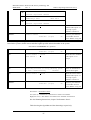
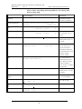
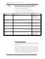
LED indicators on the Control Panel (CP)
LED indicator
Indicating
L7
General fault (yellow)
Fault(s) (i.e. not acknowledged fault(s)) and/or
acknowledged but not corrected fault(s).
L8
Disablements (yellow)
Something in the system is disabled / disconnected.9
Blinking: Single encapsulated reset performed 7.
L9
Test mode (yellow)
One or more zones are in "test mode".
L10
Door open (yellow)
A door is open.10
L11
Fault tx activated (yellow)
One or more not acknowledged faults in the system.
Output(s) for fault tx (routing equipment) is(are) also
activated, if not disabled before.
Test of routing equipment in progress (see menu
H1).
L12
Service (yellow)
One or more sensors have reached the service level.
See menu H4/U6.
L13
Fault / Disablements
Alarm devices (yellow)
One or more supervised outputs (type 3 = alarm
device) in the system are disabled.
Blinking: One or more supervised outputs (type 3 =
alarm device) have generated fault(s).
L14
System fault (yellow)
EBL512 is not running (because of SW / CPU /
memory fault).
L15
Fault / Disablements
Fire brigade tx (yellow)
Output(s) for fire brigade tx (routing equipment)
is(are) disabled via menu (H8/S1 or H2/B3) or via an
open door.10
Blinking: One or more supervised outputs (type 4 =
routing equipment) have generated fault(s).
L16
Fire brigade tx delay
(yellow)
Alert annunciation is activated.11, i.e. "Acknowledge
time" or "Investigation time" is running and output(s)
for routing equipment (fire brigade tx) are not
activated.
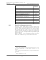
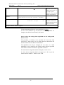
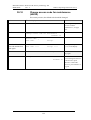
Push buttons / Keypad on the Control Panel (CP)
Key/push button
Operation/function
P6
Used to acknowledge the faults shown in menu H6.
Fault acknowledge
9
See also chapter ""Silence Alarm devices" / Silence before a fire alarm",
page 25.
10
See chapter "Door open", page 29.
11
Alert annunciation function described in EBL512 Planning Instructions,
chapter "Alert annunciation".
18
Matsushita Electric Works Fire & Security Technology AB
MEW00228
Rev: 2
EBL512 Operating Instructions V2.1.x
(yellow)
P7
Paper feed (white)
Used for paper feed (when a built-in printer is available). 12
P8
Access (white)
Used to log on, i.e. to get access to the menu tree (via an access
code) to carry out disablements, etc.
P9
Return (white)
Used to stop input of data, leave a menu ("one step up") and to
log off.
1 – 9 and 0
Numeric keys for the figures 0-9.
C
Used to clear /delete just written data.
A
Used to accept a menu and accept input of data.
← →
↑ ↓
Left / right keys are used to move the cursor in a menu.
Up / down keys are used to scroll between the menus.
12
In Chinese convention only the following is valid: If "P7" and "C" are
pressed simultaneously, the printer will be disabled. This is indicated by the
LED "Printer disabled". The printer will be disabled until re-enabled again,
i.e. "P7" and "C" are pressed simultaneously. All information that should
have been printed while the printer was disabled, will be lost (not printed).
19
Matsushita Electric Works Fire & Security Technology AB
MEW00228
Rev: 2
6
EBL512 Operating Instructions V2.1.x
Normal operation
When the control unit / system is in normal operation, i.e. no fire
alarm and normally no fault, no disablement, no service signal, no
zones in test mode, no activated interlocking in / outputs and/or no
open doors, only the LED "Operation" (L6) is to be lit.
6.1
Alphanumeric display in the control unit
In normal operation, there shall be no information shown in the
alphanumeric display in the control unit but some information can be
shown. The type of information and the priority order is as follows:
1. Fire alarms 13
2. Co-incidence alarms
3. Pre-warnings
4. Evacuate information (only valid in "British Standard" and
"British Standard Marine Application" conventions)
5. Faults (not acknowledged)
6. Disablements
7. Zones in Test mode
8. Interlocking inputs / outputs active (not valid in Chinese
convention)
NOTE!
The different type of alarms, faults, etc. are described in other parts of
this document.
13
Fire alarm have a "log off function", i.e. if a menu window is open when a
fire alarm is activated, an automatic menu log off will be take place and the
fire alarm will be presented in the alphanumeric display instead.
Some information is available and some actions are possible to perform via
the "Fire alarm menu", see chapter "Fire alarm", page 34.
20
Matsushita Electric Works Fire & Security Technology AB
MEW00228
Rev: 2
7
EBL512 Operating Instructions V2.1.x
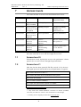
Access levels
The control unit has six access levels for different kind of users.
Access level 0
Door closed
Anybody
Scroll / browse through
the queued alarms
Access level 1
Open door
(key is needed)
Fire brigade personnel
Fire alarm handling
Access level 2
Access code for Building occupier
level 2 (or 3 or 4)
is required
Installation handling,
monthly tests,
disablements, etc.
Access level 3
Access code for
level 3 (or 4) is
required
Service personnel
Service, maintenance
Access level 4
Access code for
level 4 is
required
Service /
commissioning
engineer
Service, commissioning
the system, etc.
Access level 5
Access code for
level 5 is
required
Service /
commissioning
engineer
Code to connect a PC,
i.e. for Win512.
The access codes can be changed. To change a code you have to
know the valid code or use a code for a higher access level.
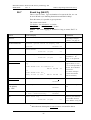
7.1
Access level 0
With the door closed, anybody has access to the push button "Alarms
queued" (P1) to scroll / browse through the queued alarms.
7.2
Access level 1
After the door has been opened (LED "Key switch" is lit), the user /
fire brigade personnel will be able to use the push buttons / keypad to:
(P2) Silence the buzzer in the c.i.e.
(P3) Silence the alarm devices (sounders) in the system.
(P4) Reset fire alarm(s).
(P5) Evacuate (start the sounders).14
(P7) Paper feed (when built-in printer is available.
(P8) Get access (after login) to some menus/functions in the system.15
14
Only valid in the "British Standard" convention. In "Polish" (CNBOP)
convention, this button is used for "Alert annunciation Acknowledge".
15
Normally, the fire brigade personnel have no access code.
21
Matsushita Electric Works Fire & Security Technology AB
MEW00228
Rev: 2
7.3
EBL512 Operating Instructions V2.1.x
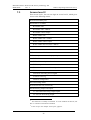
Access level 2
From access level 1, the user can login to access level 2, which gives
access to the following menus:
H1 Perform monthly test.
H2 Disable or re-enable.
B1 Disable zone
B2 Disable zone / address
B3 Disable control output
B4 Re-enable zone
B5 Re-enable zone / address
B6 Re-enable control output
B7 Re-enable non-reset zone / address16
B8 Control on / Control off
B9 Alarm devices on / Alarm devices off
H3 Set calendar and clock.
H4 Present system status on display and printer.
U1 Disablement
U2 Disablement by time channel.
U3 Show open doors.17
U4 Activated 2-zone / address dependent zone / address.
U5 Show sensor values.
U6 Sensors activating service signal
U7 Show event log
U8 Show configuration
H6 Acknowledge faults.
H7 Perform zone test (Test mode).
H9 Interlocking outputs and inputs
C1 Activated interlocking outputs/inputs
C2 Activate interlocking output
16
This function is normally not enabled. It can be enabled via Win512, but
this is a violation to the EN54-2 standard.
17
A door is open. See chapter "Door open", page 29.
22
Matsushita Electric Works Fire & Security Technology AB
MEW00228
Rev: 2
EBL512 Operating Instructions V2.1.x
C3 Reset interlocking output
C4 Disable interlocking output
C5 Re-enable interlocking output
H10 Change access code for daily duties (access level 2).
7.4
Access level 3
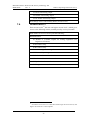
From access level 218, the user can login to access level 3, which gives
access to the following menus, normally used by service personnel:
Same menus as in access level 2 plus the following:
H8 Maintenance
S1 Disable or re-enable outputs for routing equipment (Fire
brigade tx & Fault tx)
S2 Disconnect loop.
S3 Re-connect loop.
S4 Acknowledge service signal.
S5 Clear weekly average.
S6 Safe shut down of control unit.
S7 Activate address in alarm mode.
S8 Synchronize the control units.
S9 Change access code for maintenance (access level 3).
18
If code for access level 3 or 4 has been used to login to access level 2, new
login to access level 3 is not required.
23
Matsushita Electric Works Fire & Security Technology AB
MEW00228
Rev: 2
7.5
EBL512 Operating Instructions V2.1.x
Access level 4
From access level 219, the user can login to access level 4, which gives
access to the following menus, normally used by Service /
Commissioning Engineers:
Same menus as in access level 2 and 3 plus the following:
H5 Service
A1 Calibration of supervised outputs
A2 Sensitive fault detection mode
A3 Direction for communication on COM-/BS4-loop
A4 Show information about site specific data.
A5 Display current consumption in control unit
A6 Display current consumption on COM-/BS4-loop
A7 Display statistics for COM-loop
A8 Select unit on COM-loop (and BS4 loop) to use for trigging
A9 Change access code for PC-communication (access level 5).
A10 Change access code for service (access level 4).
7.6
Access level 5
Used by Service / Commissioning Engineers when a PC is to be
connected to the control unit, i.e. when Win512 is to be used for
backup, downloading site specific data, downloading SW / settings /
configurations / C.U. and system data, on-line status checking, etc.
19
If code for access level 4 has been used to login to access level 2, new
login to access level 4 is not required.
24
Matsushita Electric Works Fire & Security Technology AB
MEW00228
Rev: 2
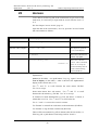
8
EBL512 Operating Instructions V2.1.x
"Silence Alarm devices"
In the control unit (on the FBP) there is a push button (P3) "Silence
Alarm devices". Depending on convention, the function can vary.
8.1
Silence before a fire alarm
In most conventions is this function not valid since it is a violation to
the EN54-2 standard.
If the push button "Silence Alarm devices" is pressed before a fire
alarm / fault, the following will happen:
• LED "Disablements" (L8) will light up (steady ON)
• outputs programmed for sounders (type 3 = alarm devices)
will be disabled
If case of a fire alarm, the sounders will remain turned OFF (not
sound).
To reset this function, press "Silence Alarm devices" once more. The
LED will be turned OFF (if there are no other disablements in the
system), indicating a normal state.
8.2
Silence during a fire alarm
If the push button "Silence Alarm devices" is pressed during a fire
alarm, the following will happen:
• LEDs "Fire" (L1) and "Alarms queued" 20 (L2) changes from
blinking (0.8 / 0.8) to steady ON
• activated outputs, programmed for sounders (type 3 = alarm
devices), will be turned OFF
In case of a new fire alarm, or if the push button "Silence Alarm
devices" is pressed again, the sounders (i.e. the outputs), will
automatically be turned ON again and LEDs "Fire" and "Alarms
queued" starts blinking.
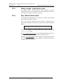
8.3
Alarm device on / Alarm device off
Via menu H2/B9, all outputs, programmed for sounders (type 3 =
alarm devices), can be collective turned OFF (disabled), indicated by
LED "Disablements" (L8) and LED Fault / Disablements "Alarm
devices" (L13) steady ON.
In case of a fire, the sounders will remain turned OFF (disabled), i.e
the alarm devices will not sound.
They will remain turned OFF (disabled) until they are turned ON (reenabled) again, via menu H2/B9.
20
When more than one fire alarm is activated.
25
Matsushita Electric Works Fire & Security Technology AB
MEW00228
Rev: 2
9
EBL512 Operating Instructions V2.1.x
"Silence buzzer"
The buzzer in the control unit will sound for:
•
pre-warning (0.8 / 5 sec.)
•
2-zone dependent or 2-unit dependent fire alarm: When only one
zone or one zone / address (alarm point) is in alarm status (0.8 / 5
sec.)
•
fire alarm (0.8 / 0.8 sec.)
•
fault (steady)
•
disablements and faults when the door to the C.U. is being closed
(1 sec.)
•
activated interlocking input (0.4 / 0.4 sec.), if this option is
selected via Win512.
Press "Silence buzzer" (P2) to silence the sounding buzzer.
When the buzzer is silenced (via P2), it will sound again (re-sound)
for a new "alarm" / fault / activated interlocking input.
"Old" front
For the function described above, the "new" front , with the push
button "Silence buzzer" (P2) is required.
The "old" front (without the push button "Silence buzzer") results in
the following function: The buzzer is silenced via the control unit
door switch, i.e. the buzzer will be silent as long as the door is open.
In Win512 ("System" dialog box) is the "Silence Buzzer By Door
Switch" check box unmarked as default. When this check box is
marked (required with the "old" front), the buzzer is turned off as long
as the control unit door is open but this function is a violation to the
EN54-2 standard.
26
Matsushita Electric Works Fire & Security Technology AB
MEW00228
Rev: 2
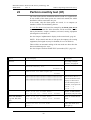
10
EBL512 Operating Instructions V2.1.x
Controls ON / Controls OFF
Via menu H2/B8, all control output types:
0 = control (general)
1 = fire ventilation
2 = extinguishing system21
can be collective turned OFF (disabled), indicated by LED
"Disablements" (L8).
They will remain turned OFF (disabled) until they are turned ON (reenabled) again, via menu H2/B8.
21
Also the "Extinguish equipment output" on the German FBP interface
board 1583.
27
Matsushita Electric Works Fire & Security Technology AB
MEW00228
Rev: 2
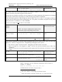
11
EBL512 Operating Instructions V2.1.x
Evacuate
Only valid for the "British Standard" convention. English front with
the push button "Evacuate" (P5) is also required.
When the push button "Evacuate" (P5) is pressed, all outputs,
programmed for sounders (type 3 = alarm devices), will be collective
turned ON. This is indicated by the following information in the
alphanumeric display:
Evacuate in progress
They will remain turned ON until they are turned OFF by pressing the
push button "Evacuate" (P5) again.
NOTE! The alarm devices (sounders) will always be steady activated
(sound continuously) irrespective of the fact that the outputs can be set
to anything else for fire alarm (e.g. intermittent).
28
Matsushita Electric Works Fire & Security Technology AB
MEW00228
Rev: 2
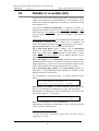
12
EBL512 Operating Instructions V2.1.x
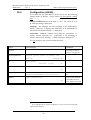
Door open
A special key is used to open the control unit door to get access to the
system, see chapter "Access levels", page 21. The same type of key is
also used to open the ext. FBP door. Door open is indicated by LED
"Door open" (L10). In Win512 ("System" dialog box, "Door open"
tab), the following can be programmed (default settings shown):
12.1
LED "Door open"
Indication door open affected by
12.2
~
Door in any control unit or any external FBP: Door open in a
C.U. is indicated by LED "Door open" in all C.U:s and in all ext.
FBPs. Door open in an ext. FBP is indicated by LED "Door
open" in all C.U:s and in all ext. FBPs.
{
Door in any control unit: Door open in a C.U. is indicated by
LED "Door open" in all C.U:s and in all ext. FBPs. Door open
in an ext. FBP is indicated by LED "Door open" in that ext. FBP
only.
{
Door in control unit or external FBP connected to own
control unit: Door open in a C.U. is indicated by LED "Door
open" in that C.U. and all ext. FBPs connected to that C.U. Door
open in an ext. FBP is indicated by LED "Door open" in the C.U.
it is connected to and all ext. FBPs connected to that C.U.
{
Door in control unit: Door open in a C.U. is indicated by LED
"Door open" in that C.U. and in all ext. FBPs connected to that
C.U. Door open in an ext. FBP is indicated by LED "Door open"
in that ext. FBP only.
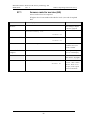
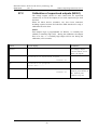
Outputs for routing equipment (Fire
brigade tx and Fault tx)
Disablement of routing equipment
~
No disablement: Door open in a C.U. or an ext. FBP will not
disable the output(s) for routing equipment (Fire brigade and fault
tx).
{
Disable by door in any control unit: Door open in any C.U.
will disable the output(s) for routing equipment (Fire brigade and
fault tx) in all C.U:s.
{
Disable by door in any control unit or any external FBP:
Door open in any C.U. or any ext. FBP will disable the output(s)
for routing equipment (Fire brigade and fault tx) in all C.U:s.
Disabled outputs for routing equipment are indicated by the LED
"Disablements" (L8) and "Fault / Disablements Fire brigade tx"
(L15).
29
Matsushita Electric Works Fire & Security Technology AB
MEW00228
Rev: 2
EBL512 Operating Instructions V2.1.x
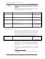
13
Technical number / Presentation
number
13.1
Technical number for COM loop units
The technical number, NNNNNN, is used when programming all
units connected to the COM loops.
Technical number is also used to identify which unit has generated a
fault.
Regarding DIL-switch address setting, see dwg 512-71.
Regarding the Address setting tool 3314: Addresses 001 – 127 can be
set (not 000).
30
Matsushita Electric Works Fire & Security Technology AB
MEW00228
Rev: 2
13.2
EBL512 Operating Instructions V2.1.x
Technical number for BS4 loop units
Autronica interface board 158422 (four BS4 loops) is required in the
control unit.
The technical number, NNNNNN, is used when programming all
units connected to the BS4 loops.
Technical number is also used to identify which unit has generated a
fault.
NOTE! In the technical number for unit connected to a BS4 loop, the
board number 4 = Autronica interface board 0, the board number 5 =
Autronica interface board 1, the board number 6 = Autronica interface
board 2 and the board number 7 = Autronica interface board 3 in the
control unit.
In fault messages for Autronica interface boards, the following
information is shown: Control unit (00-29), BS4 board (0-3) and if
required BS4 loop (0-3)
22
Can only be used in Swedish (SBF) convention.
31
Matsushita Electric Works Fire & Security Technology AB
MEW00228
Rev: 2
13.3
EBL512 Operating Instructions V2.1.x
Presentation number
For each fire alarm point / input / zone, a presentation number,
NNN-NN, has to be programmed. This number is shown in the FBP
display(s)23, to identify the point / zone generating fire alarm. It is
also used to disable / re-enable fire alarm points / zones and in control
conditions (expressions) to activate the programmable outputs.
Together with the zone number and the address, a user definable, 40
characters, text message can be displayed (if programmed).
NOTE! Zone numbers 001-999 can be used but > 512 alarm points or
zones in one c.i.e. is a violation to the EN54-2 standard.
23
The presentation number (or a user definable, 40 characters, text message)
can also shown in the display units connected to the COM loops.
32
Matsushita Electric Works Fire & Security Technology AB
MEW00228
Rev: 2
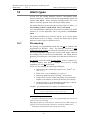
14
EBL512 Operating Instructions V2.1.x
Alarm types
In case of a fire, analog detectors (sensors), conventional smoke
and/or heat detectors, manual call points and programmable inputs can
generate fire alarm. When somebody illegally breaks into a key
cabinet, it will also generate a fire alarm (key cabinet alarm).
The analog detectors can also generate two other types of "alarm", i.e.
Pre-warning and Heavy smoke alarm / Heavy heat alarm.
"Two unit dependent" addressable alarm points (normally only smoke
detectors) or "2-zone dependent" zones, can generate a Co-incidence
alarm.
The system can handle up to 15360 fire alarms. Up to 512 fire alarms
will be shown in the c.i.e. display. No more fire alarms will be shown
until one or more of the 512 alarms are reset.
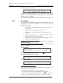
14.1
Pre-warning
Pre-warning is a programmable option that will not be enabled if not
programmed (in Win512). Note! Pre-warnings activated in other
control units in the system will always be presented in all control units
and all programmable outputs in the system (with trigger condition
pre-warning) will be activated (if not disabled). An analog detector
generates pre-warning for a lower alarm level than the fire alarm level.
24
Pre-warning can be used when an early alarm / action is required (e.g.
a "soft" computer shut down). Normal alarm devices, routing
equipment, etc. will not be activated.
In case of a pre-warning, the following will happen:
• The buzzer in the control unit sounds 0.8 sec. each 5th sec.
(0.8 / 5 sec.).
• LEDs "Fire" (L1) are blinking (0.8 / 0.8 sec.).
• Outputs programmed for pre-warning25 are activated.
• On the first row in the control unit display, the presentation
number (zone/address) is shown (for the first pre-warning).
• On the second row, a user definable text message (= that for
fire alarm) will be shown (if programmed).
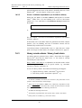
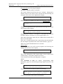
Example; pre-warning zone 123, address 45 (within zone 123):
Pre-warning detector 123/45
(user definable text message)
24
See EBL512 Planning Instructions. Any programmable input can also be
used to activate a pre-warning.
Regarding the BS4 exp. board 1584 for Autronica devices (BS4 loops), prewarning can also be generated by detector(s) connected to address units.
25
And outputs programmed for each specific pre-warning.
33
Matsushita Electric Works Fire & Security Technology AB
MEW00228
Rev: 2
EBL512 Operating Instructions V2.1.x
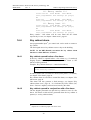
Example; pre-warning zone 123:
Pre-warning zone 123
(user definable text message)
If more than one pre-warning are generated, the LEDs "Alarms
queued" (L2) are blinking and the pre-warnings will be automatically
scrolled (each five seconds).
Pre-warning is automatically reset see chapter "Alarm reset", page 41.
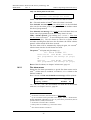
14.2
Fire alarm
See also chapter "Alphanumeric display in the control unit", page 20.
According to the EN54-2 standard26, in case of a fire alarm, the
following will happen:
• The buzzer in the control unit sounds 0.8 sec. each 0.8th sec.
(0.8 / 0.8 sec.).
• LEDs "Fire" (L1) are blinking (0.8 / 0.8 sec.).
• Output(s) for routing equipment (Fire brigade tx) is (are)
activated.
• Outputs for sounders (type 3 = alarm devices) are activated.
• Outputs for fire alarm27 are activated.
• In the control unit display (and ext. FBP28 display), the fire
alarms are presented as follows.
Only one alarm point activated in a zone is presented as zone-address
(POINT: or LAST:)
Two or more alarm points activated in a zone is presented as zone
(ZONE: or LAST:).
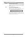
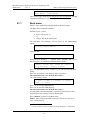
One alarm point
POINT: 123-45
No.:001
User definable text message for 123-45
More than one alarm point in a zone
A conventional zone (zone line input)
or
ZONE: 123
No.:001
User definable text message for zone 12329
More than one zone
ZONE: 234
LAST: 567
No.:002
User definable text message for zone 234
26
Via Win512 can "Point alarm presentation" be selected (which is a
violation to the EN54-2 standard).
27
And outputs programmed for each specific fire alarm.
28
Only the ten first fire alarms will be displayed in the ext. FBPs.
29
More than one alarm point in the same zone: If no user definable text
message is programmed, the text "Many alarms in zone" will be shown.
34
Matsushita Electric Works Fire & Security Technology AB
MEW00228
Rev: 2
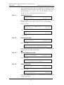
EBL512 Operating Instructions V2.1.x
Only one alarm point in each zone
POINT: 123-45
LAST: 789-01
No.:003
User definable text message for 123-45
LAST = The most recent zone-address that activated fire alarm.
No. = The total number of zones30 where fire alarm is activated.
User definable text message For an alarm point it is the individual
(free) text for the alarm point (if programmed) or the default control
unit text (if programmed).
User definable text message For a zone it is the individual (free) text
for the zone (if programmed) or the text "Many alarms in zone".
LEDs "Alarms queued" (L2) blinking (0.8 / 0.8 sec.). More than
one fire alarm is activated.31 To scroll through the zones, use the push
button "Scroll" (P1). The fire alarms are stored in a circular buffer
and when scrolling from the last to the first alarm, the LEDs "Alarms
queued" will be turned off for three seconds.
The first alarm will be automatically dispayed again, 20 seconds32
after the latest time the "Scroll" button was used.
The printer 33 will print each fire alarm, e.g.:
*** Fire Alarm ***
Point: 123-45
Time HH.MM
Date MM-DD
User programmable text message (if progr.)
or
Zone: 123
Time HH.MM
Date MM-DD
User programmable text message (if progr.)
Reset of the fire alarms, see chapter "Alarm reset", page 41.
14.2.1
Fire alarm menu
During the fire alarm presentation, a special fire alarm menu can be
used.34 (If this menu is excluded, via Win512, it is a violaton to the
EN54-2 standard).
Press "Access" and the user definable text message will be replaced:
ZONE: 123
Display alarms
LAST: 789
No.:003
ACCEPT? X1
"A", "È", "Ç", "Æ", "Å" and "Return" are used like in the normal
menu tree, see chapter "Access", page 68.
30
In Chinese convention, the total number of alarm points.
Up to 512 alarms can be presented in the display. Alarm = ZONE and/or
ZONE-ADDRESS (depending on zone or point alarm presentation) but all
possible alarms (15360) can be stored.
32
In Chinese convention after 3 minutes.
33
When printer is available (e.g. control unit 1549).
34
Not valid in Chinese convention.
31
35
Matsushita Electric Works Fire & Security Technology AB
MEW00228
Rev: 2
EBL512 Operating Instructions V2.1.x
The original presentation (the user definable text message) will be
automatically displayed again, 20 seconds after the latest time any of
the push buttons "A", "È", "Ç", "Æ", "Å" and "Return" was used.
Scroll ("È", "Ç") to the wanted menu and press "A".
14.2.1.1
Display alarms (X1)
ZONE: 123
Display alarms
LAST: 789
No.:003
ACCEPT? X1
All fire alarms, also several alarm points in one zone, will be
displayed here, in zone - address order (i.e. up to 15360 alarms).
Press "A". E.g.:
ZONE: 123
POINT: 123-45
LAST: 789
No.:003
No.:001
ZONE: 123
ZONE: 234
LAST: 789
No.:003
No.:002
LAST: 789
No.:003
ACCEPT? X2
"È"
…and so on.
14.2.1.2
Display faults (X2)
ZONE: 123
Display faults
Press "A". E.g.:
ZONE: 123
LAST: 789
No.:003
FAULT: Battery not connected CU xx
Only the fault message, for the fault respectively, is displayed here,
not date, time and "status" information.
14.2.1.3
Display disablements (X3)
ZONE: 123
LAST: 789
Display disablements
No.:003
ACCEPT? X3
Press "A". E.g.:
ZONE: 123
LAST: 789
Zone XXX address XX disabled
14.2.1.4
No.:003
Disable zone (X4)
ZONE: 123
Disable zone
LAST: 789
No.:003
ACCEPT? X4
ZONE: 123
LAST: 789
Disable zone: 000
No.:003
ACCEPT?
Press "A". E.g.:
Write zone number and press "A". If more zones are to be disabled,
repeat the procedure.
36
Matsushita Electric Works Fire & Security Technology AB
MEW00228
Rev: 2
14.2.1.5
EBL512 Operating Instructions V2.1.x
Re-enable zone (X5)
ZONE: 123
Re-enable zone
LAST: 789
No.:003
ACCEPT? X5
ZONE: 123
LAST: 789
Re-enable zone: ZZZ
No.:003
ACCEPT?
Press "A". E.g.:
This is a list of disabled zones. Scroll to or write the wanted zone
number and press "A". If more zones are to be re-enabled, repeat the
procedure.
14.2.1.6
Control on/off (X6)
ZONE: 123
Control on/off
LAST: 789
No.:003
ACCEPT? X6
Press "A". E.g.:
ZONE: 123
LAST: 789
Control on (=1) or off (=0)? 1
No.:003
ACCEPT?
To activate Control off, press "0" and "A". (To activate Control on,
press "1" and "A".). For more information, see chapter "Control on /
Control off (H2/B8), page 79.
14.2.1.7
Alarm devices on/off (X7)
ZONE: 123
LAST: 789
Alarm devices on/off
No.:003
ACCEPT? X7
Press "A". E.g.:
ZONE: 123
LAST: 789
Alarm devices on(=1) off(=0)? 1
No.:003
ACCEPT?
To activate Alarm devices off, press "0" and "A". (To activate Alarm
devices on, press "1" and "A".). For more information, see chapter
"Alarm devices on / Alarm devices off (H2/B9), page 80.
14.2.2
Alert annunciation
Indications, print-outs, actions etc. as for a normal fire alarm except
output(s) for routing equipment (fire brigade tx), which will not
be activated. This is indicated by the LED "Fire brigade tx delay"
(L16). The alarm has to be acknowledged35 and reset within an
acknowledge time and an investigation time respectively, otherwise
the output(s) for routing equipment (fire brigade tx) will be activated.
See EBL512 Planning Instructions for more information.
35
LED "Acknowledge" is indicating that the push button "Acknowledge"
has been activated. A busy system can cause a time delay (up to 10 seconds)
before the fire alarm is acknowledged.
37
Matsushita Electric Works Fire & Security Technology AB
MEW00228
Rev: 2
EBL512 Operating Instructions V2.1.x
Acknowledgement and reset of the alarm is normally done on a 2235
Display unit36. See also chapter "Alarm reset", page 41.
14.2.3
2-zone / address dependence (co-incidence alarm)
When only one zone or one zone / address (alarm point) is in alarm
status37, LEDs "Fire" (L1) are blinking (0.8 / 0.8 sec.), the buzzer
sounds (0.8 / 5 sec.) and there is a Co-incidence alarm presentation in
the display.
Co-incidence alarm detector ZZZ/AA
or
Co-incidence alarm zone ZZZ
See also chapter "Activated 2-zone/address dependent zone/address
(H4/U4)", page 85.
If more than one Co-incidence alarm are generated, the LEDs "Alarms
queued" (L2) are blinking and the Co-incidence alarms will be
automatically scrolled (each 5th second).
Co-incidence alarm is automatically reset (i.e. when the zone / alarm
point is no longer in alarm status), see chapter "Alarm reset", page 41.
14.3
Heavy smoke alarm / Heavy heat alarm
An analog detector generates heavy smoke / heat alarm for a higher
alarm level38 than the fire alarm level, i.e. fire alarm is already
activated by the same detector.
Heavy smoke / heat alarm is a confirmation on that the smoke or heat
is increasing and can be used for special actions, e.g. automatic
activation of smoke ventilation, etc.
In case of a heavy smoke / heat alarm, the following will happen:
• Outputs for heavy smoke / heat alarm39 are activated.
• Each heavy smoke / heat alarm is printed40, e.g.:
36
In "Polish" (CNBOP) convention, the "Evacuate" (P5) push button can be
used for "Alert annunciation Acknowledge".
37
When two or more zones or units (zone / addresses), dependent on each
other, are in alarm status at the same time, normal fire alarm will be activated
in the system. See also EBL512 Planning Instructions.
38
See EBL512 Planning Instructions.
39
And outputs programmed for each specific heavy smoke / heat alarm.
40
When printer is available (e.g. control unit 1549).
38
Matsushita Electric Works Fire & Security Technology AB
MEW00228
Rev: 2
EBL512 Operating Instructions V2.1.x
*** Heavy smoke ***
Point: 123-45
Time HH.MM
Date MM-DD
User programmable text message (if progr.)
or
Zone: 123
Time HH.MM
Date MM-DD
User programmable text message (if progr.)
*** Heavy heat ***
Point: 123-45
Time HH.MM
Date MM-DD
User programmable text message (if progr.)
or
Zone: 123
Time HH.MM
Date MM-DD
User programmable text message (if progr.)
Heavy smoke / heat alarm will be reset when the fire alarm
respectively is reset, see chapter "Alarm reset", page 41.
14.4
Key cabinet alarm
One programmable input41 per control unit can be used to connect a
key cabinet.
The fire brigade uses a key cabinet to store a key to the building.
NOTE! In the DBI (Danish) convention the key cabinet alarm
function is a little different, see below.
14.4.1
Key cabinet opened before a fire alarm
If the key cabinet is opened before a fire alarm (e.g. if somebody
illegally breaks into a key cabinet), a key cabinet alarm (a "fire
alarm") will be generated.
Example; Key cabinet alarm (xx = control unit number):
POINT: KEY-xx
Alarm from key cabinet
No.:001
It will be printed like a normal fire alarm (when printer is available),
see chapter "Fire alarm", page 34.
Key cabinet alarm is reset like a normal fire alarm, see chapter "Fire
alarm reset, page 41.
This alarm will also generate a fault message, see chapter "Key
cabinet alarm reset", page 43. It is indicated by LED "Fault" (L8).
Note! "Fault tx" output(s) will not be activated by this fault.
14.4.2
Key cabinet opened in conjunction with a fire alarm
The fire brigade personnel can open the key cabinet in case of a fire
alarm. No alarm or fault will be generated when the key cabinet is
opened (i.e. no key cabinet alarm).
41
Input I0-I3 or COM loop input unit can be used.
39
Matsushita Electric Works Fire & Security Technology AB
MEW00228
Rev: 2
EBL512 Operating Instructions V2.1.x
14.4.2.1
Restoring the key after a fire alarm
When all fire alarms (in the system) are reset (see chapter "Alarm
reset", page 41), the key has to be restored in the key cabinet within 5
minutes. If not, a fault will be generated, see chapter "Key cabinet
alarm reset", page 43.
14.4.3
Key cabinet alarm, DBI convention
NOTE! Only valid for the DBI (Danish) convention.
When the key cabinet is opened, the "Fault tx" output(s) will be
activated and a "key cabinet fault" will be generated:
FAULT: Key cabinet, control unit: xx
Date: MM-DD
Time: HH:MM
(In Danish: "FEJL: Nøgleskab, central xx")
When this fault is acknowledged (see chapter "Acknowledge
FAULTS (H6)", page 109), there is a 5 minutes delay before a new
"key cabinet fault" can be generated again.
40
Matsushita Electric Works Fire & Security Technology AB
MEW00228
Rev: 2
15
Alarm reset
15.1
Pre-warning reset
EBL512 Operating Instructions V2.1.x
Pre-warning is automatically reset.
15.2
Fire alarm reset
NOTE! The detectors having activated the fire alarms shall, after
reset, be inspected, tested and replaced when required.
One of the following alarm reset alternatives is selected via Win512.
"Multiple reset" is default.
15.2.1
Multiple reset
All the fire alarms will be reset by pressing "Reset" (P3). (According
to the EN54-2 standard).
NOTE! The push button has to be pressed in for min. 0.5 sec.
When all fire alarms are reset, LEDs "Fire" (L1) and "Alarms
queued" (L2) are turned OFF and the display is empty42.
All outputs (for fire alarm) have been de-activated.
If a key cabinet is installed, the key (to the building) has to be put
back into the key cabinet within 5 minutes. If not, a fault will be
generated and a fault message will be shown in the display, see
chapter "Key cabinet alarm reset, page 43.
15.2.2
Single reset
Each fire alarm has to be reset one by one. (This function, set in
Win512, is a violation to the EN54-2 standard.) 43
Press "Reset" (P3) to reset the fire alarm, shown in the display, on the
first row to the left
NOTE! The push button has to be pressed in for min. 0.5 sec.
Output(s), programmed for this fire alarm, is (are) de-activated.
If more than one fire alarm is activated (i.e. LEDs "Alarms queued"
(L2) are lit) the next fire alarm in the queue is now shown in the
display, on the first row to the left. It has to be reset the same way as
the first one.
When all fire alarms are reset, LEDs "Fire" (L1) and "Alarms
queued" (L2) are turned OFF and the display is empty42.
42
If there is a fault condition (e.g. caused by the fire), a fault message will
now be shown in the display.
43
When "Single reset" or "Single encapsulated reset" is used, you can make a
"Multiple reset" by pressing "Reset" (P4) and 0.1 sec. later also press "A" (in
the keypad) and hold them pressed for > 0.5 sec.
41
Matsushita Electric Works Fire & Security Technology AB
MEW00228
Rev: 2
EBL512 Operating Instructions V2.1.x
All outputs (for fire alarm) have been de-activated.
If a key cabinet is installed, the key (to the building) has to be put
back into the key cabinet within 5 minutes. If not, a fault will be
generated and a fault message will be shown in the display, see
chapter "Key cabinet alarm reset, page 43.
15.2.3
Single encapsulated reset (Zone/Detector not reset)
Like "Single reset" but with the encapsulation function as follows:
Normally if an alarm point or zone is reset while still in alarm status,
it will activate a new fire alarm within 20 seconds. (According to the
EN54-2 standard.)
When "Single encapsulated reset" is performed, an alarm point or
zone still in alarm status will not activate a new fire alarm. It becomes
encapsulated (sort of disabled) and has to be re-enabled via menu
H2/B7 before it can activate a new fire alarm again. (This function,
set in Win512, is a violation to the EN54-2 standard.)
LED "Disablements" (L8) is blinking, indicating that one or more
zones / alarm points have been encapsulated. To re-enable, see
chapter "Re-enable non-reset zone / address (H2/B7), page 78.
NOTE!
When "Multi reset" or "Single reset" is used, encapsulated reset can be
done by pressing "Reset" (P4) and 0.1 sec. later also press "Alarms
queued" (P1) and hold them pressed for > 0.5 sec.
By Single reset: The fire alarm displayed in the LCD (first row to the
left) will be encapsulated.
By Multiple reset: The fire alarm displayed in the LCD (first row to
the left) will be encapsulated or the points in alarm status within one
zone will be encapsulated or the whole zone (conventional) will be
encapsulated.
15.2.4
Alert annunciation
Regarding the function, see chapter "Alert annunciation", page 37 and
EBL512 Planning Instructions, chapt. "Alert annunciation".
Reset of the alert annunciation fire alarm(s) is normally done on a
2235 Display unit (push button "Reset") but can be done via a
programmable input or in the c.i.e. (push button "Reset" (P4)). If
more than one "alert annunciation alarm" are active, they will be reset
all at a time.
NOTE! Reset via 2235 Display unit or programmable input is only
possible to do during the alert annunciation period, i.e. alert
annunciation fire alarm(s) only. Normal fire alarms can not be reset.
15.2.5
Co-incidence alarm
Co-incidence alarm is automatically reset (i.e. when the zone / alarm
point is no longer in alarm status). See also chapter "2-zone / address
dependence (co-incidence alarm)", page 38.
42
Matsushita Electric Works Fire & Security Technology AB
MEW00228
Rev: 2
15.3
EBL512 Operating Instructions V2.1.x
Heavy smoke / heat alarm reset
If a heavy smoke / heat alarm has been activated, it will be
automatically reset at the same time as the corresponding fire alarm is
reset and resp. output(s) will be de-activated.
15.4
Key cabinet alarm reset
Not valid for the DBI (Danish) convention, see chapter "Key cabinet
alarm, DBI convention", page 40.
After reset of the key cabinet alarm ("fire alarm"), a fault message is
shown in the display to inform the user that the key cabinet has been
opened.
FAULT: Key cabinet, control unit: xx
Date: MM-DD
Time: HH:MM
If the key cabinet is closed again, the "status" information
"Serviced" is added.
This key cabinet fault message is to be acknowledged the same way as
a "normal" fault, see chapter "Fault acknowledge", page 56.
When the key cabinet fault is acknowledged, the LED "General fault"
(L7) will be turned OFF (if the key cabinet is closed and if there are
no other faults in the system).
43
Matsushita Electric Works Fire & Security Technology AB
MEW00228
Rev: 2
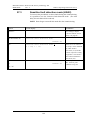
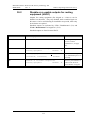
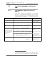
16
EBL512 Operating Instructions V2.1.x
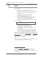
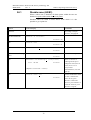
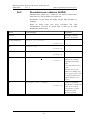
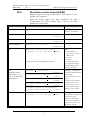
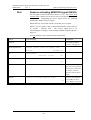
Fault
In case of a fault condition, the following has happened / will happen
in the control unit:
• The buzzer in the control unit sounds (steady ON).
• Output(s) for routing equipment (Fault tx) is (are) activated.
• Output(s) for general fault / general charge fault is (are)
activated.
• LED "Fault tx activated" (L11) is turned ON.
• LED "General fault" (L7) is turned ON.
• LEDs "Fault / Disablements Alarm devices" (L13),
"System fault" (L14) and/or "Fault / Disablements Fire
brigade tx" (L15) may be turned ON as well.
• A fault message incl. date and time is shown in the display.
Example; fault message:
FAULT: No reply techn.no. xxxxxx
Date: MM-DD
Time: HH:MM
• If more than one fault is activated, the text:
"More faults" is added after the time.
• If a fault has been corrected before it has been
acknowledged, the "status" text: "Serviced" is added
after the time.44
• Fire alarm presentation has higher priority than the fault
messages. During fire alarm presentation the faults can be
shown via the special fire alarm menu X1, see page 36.
Faults have to be acknowledged, which is done via menu H6 (see page
109). This menu is a list of all not acknowledged and acknowledged
but not corrected faults.
If a fault can not be corrected, it is important to contact service
personnel / engineer immediately.
Note!
As a warning, faults (and disablements) are also indicated by a 2-sec.
beep when an open control unit door is being closed.
44
In Win512, fault latching or not fault latching can be selected.
Fault latching (default) = the faults always have to be acknowledged.
Not fault latching = corrected faults will automatically be removed from the
fault list (menu H6).
44
Matsushita Electric Works Fire & Security Technology AB
MEW00228
Rev: 2
16.1
EBL512 Operating Instructions V2.1.x
Fault messages
Below follows a list of all fault messages, in alphabetical order:
FAULT: 1580 8 zones board x, CU xx
(8 zones expansion board, DET8)
Fault on / no communication to 1580 board No. x in control unit No.
xx. Check address setting and connections on the board. Check
programming (Win512).
FAULT: 1581 Relay board x, CU xx
(8 relays expansion board)
Fault on / no communication to 1581 board No. x in control unit No.
xx. Check address setting and connections on the board. Check
programming (Win512).
FAULT: 1582 FBP interface board x, CU xx
(External Fire Brigade Panel interface board)
Fault on / no communication to 1582 board No. x in control unit No.
xx. Check address setting and connections on the board. Check
programming (Win512).
FAULT: 1583 Extinguishing system, CU xx
Fault in the extinguishing system / equipment connected to the 1583
German Fire Brigade Panel interface board, in control unit No. xx.
FAULT: 1583 GFBP interface board, CU xx
(German Fire Brigade Panel interface board)
• Fault on / no communication to 1583 board in control unit
No. xx. Check address setting and connections on the board.
Check programming (Win512).
• Check the fuses F1 and F2 on the 1583 board.
FAULT: 1584 Autronica board x, CU xx
(Autronica interface board)
Fault on / no communication to 1584 board No. x in control unit No.
xx. Check address setting and connections on the board. Check
programming (Win512).
45
Matsushita Electric Works Fire & Security Technology AB
MEW00228
Rev: 2
EBL512 Operating Instructions V2.1.x
FAULT: 24 V for ext. equipment, CU xx
Check the fuses F2 and F4 on the connection board 1555. (Supervised
output S2 is also supplied via F2 and F4).
FAULT: 24 V for routing equipment, CU xx
Check the fuses F1 and F3 on the connection board 1555. (Supervised
output S3 is also supplied via F1 and F3).
FAULT: ASF COM-loop x, control unit xx
(ASF=2370, Addressable short circuit isolator)
This message is only shown when the control unit works in Sensitive
fault detection mode (menu H5/A2).
A short circuit, shorter / faster than the time delay for an ordinary
fault, has occurred on the COM loop. Can be used for commissioning
/ maintenance purposes.
FAULT: Battery not connected CU xx
• Batteries (2 x 12 V) are missing or not correctly connected.
• Fuse(es) F2, F3 on the charger board 1557 is(are) blown.
• Other battery fuse is blown (e.g. when the batteries are
placed outside the control unit).
FAULT: Battery output unit xxxxxx
Check the output unit battery / connections / fuse F3 (on the power
supply board) in the output unit.
FAULT: Charging ext. power supply CU xx
The fault is to be found in the external power supply equipment.
FAULT: Checksum system program, CU xx
A fault in control unit xx SW. This is very serious. Call for service
personnel/engineer immediately.
FAULT: Configuration control unit xx
46
Matsushita Electric Works Fire & Security Technology AB
MEW00228
Rev: 2
EBL512 Operating Instructions V2.1.x
Fault in the SSI = EBL512 settings downloaded from Win512.
FAULT: CU xx has no contact with CU xx
Can be shown in conjunction with new SW download.
• Check the TLON network cable / connections.
• Faulty TLON connection board. 1590.
• No power supply to the control unit.
FAULT: CU xx has wrong information
Can be shown in conjunction with new SW download.
One or more control units have data stored, which is not the same in
all control units. If a control unit restarts in conjunction with this
fault, a synchronization will start automatically, otherwise a
synchronization has to be started via menu H8/S8.
NOTE! It is important that all control units that are supposed to exist
(SSD downloaded via Win512) are running and are connected to the
TLON network. The TLON network programming has to be done.
FAULT: CU xx high current consumption
The control unit current consumption is over 2.5A, and because of
this, the battery charging is turned off. Normally this fault only
appears when starting up / expanding a system.
FAULT: Cut-off COM-loop x, CU xx
This is indicating a single break on the loop. Communication has to be
performed in both directions, to find all units.
May also be shown after a short circuit on the loop when short circuit
isolators are used (= communication in both directions).
(A double break will give the message: FAULT: No reply …..).
NOTE! Communication in both directions lasts for about ten minutes,
when a new attempt to communicate in one direction is performed. If
the break remains, a new ten minutes period starts, and so on. If the
fault is acknowledged and the break is corrected during a ten minutes
period, it will not disappear from the list until the end of the ten
minutes period.
FAULT:Cut-off input x,1580 board x,CU xx
(8 zones expansion board, DET8)
This is indicating a break or missing end of line resistor on input x
47
Matsushita Electric Works Fire & Security Technology AB
MEW00228
Rev: 2
EBL512 Operating Instructions V2.1.x
(zone line) on the 1580 board. A detector may have been removed
(stolen) from its base.
FAULT: Cut-off loop x, BS4 x, CU xx
(1584 Autronica interface board, BS4)
Cut-off (break) on the BS4 loop. This is indicating a single break on
the loop. Communication has to be performed in both directions, to
find all units.
Each 10th minute is an attempt made to comm. in one direction again.
FAULT:Cut-off loop x,CU xx, CU<->ASF0
FAULT:Cut-off loop x, CU xx,ASF 0<->ASF 1
FAULT:Cut-off loop x, CU xx,ASF 1<->ASF 2
FAULT:Cut-off loop x, CU xx,ASF 2<->ASF 3
FAULT:Cut-off loop x, CU xx,ASF 3<->ASF 4
FAULT:Cut-off loop x, CU xx,ASF 4<->ASF 5
FAULT:Cut-off loop x, CU xx,ASF 5<->ASF 6
FAULT:Cut-off loop x, CU xx,ASF 6<->ASF 7
FAULT:Cut-off loop x, CU xx,ASF 7<->CU
FAULT:Cut-off loop x, CU xx,ASF 6<->CU
FAULT:Cut-off loop x, CU xx,ASF 5<->CU
FAULT:Cut-off loop x, CU xx,ASF 4<->CU
FAULT:Cut-off loop x, CU xx,ASF 3<->CU
FAULT:Cut-off loop x, CU xx,ASF 2<->CU
FAULT:Cut-off loop x, CU xx,ASF 1<->CU
FAULT:Cut-off loop x, CU xx,ASF 0<->CU
This is indicating a single break on the COM loop "x" when one or
more short circuit isolators 2370, ASF, are connected on the loop.
Communication has to be performed in both directions, to find all
units. The break is to be found in the specified segment (e.g. ASF
3<->CU = between short circuit isolator number 3 and the control
unit). Each 10th minute is an attempt to comm. in one direction made
again.
FAULT: Display unit xxxxxx
Display unit out of work. Fault in the display unit EEPROM ("site
specific data"). Download the data again or change the EEPROM and
download the data again.
48
Matsushita Electric Works Fire & Security Technology AB
MEW00228
Rev: 2
EBL512 Operating Instructions V2.1.x
FAULT: Double addresses techn. no.: xxxxxx
Two (or more) units, connected to a BS4 loop (1584 board), have been
given the same address. Check the units.
FAULT: Earth fault (plus), CU xx
FAULT: Earth fault (minus), CU xx
Earth fault is detected. Check all cables (for damage, etc.). The
function of the control unit can not be guaranteed. Call for service
personnel/engineer.
FAULT: Earth fault, output unit xxxxxx
Check all cables connected to the output unit.
FAULT: External FBP x, board x, CU xx
The control unit can not communicate with the ext. FBP (or data
converter).
• Check the connections.
• Check the cable (break?).
• Check address DIL-switch in the ext. FBP. Is correct address
set?
• Several ext. FBPs have the same address.
• Faulty ext. FBP.
FAULT: External fuses, control unit xx
The fault is to be found in the external power supply (blown fuses,
etc.).
FAULT: External power supply, CU xx
The fault is to be found in the external power supply connected to
input in control unit xx.
FAULT: Fuse, 1580 8 zones board x, CU xx
(DET8=1580, 8 zones expansion board)
Check for blown fuse on the 1580 board.
49
Matsushita Electric Works Fire & Security Technology AB
MEW00228
Rev: 2
EBL512 Operating Instructions V2.1.x
FAULT: Fuse, 1582 FBP board x, CU xx
(External Fire Brigade Panel interface board 1582)
Check for blown fuses on the 1582 board.
FAULT: Fuse, 1584 Autron. board x, CU xx
(Autronica interface board, BS4)
Blown fuse on the 1584 board. The fuse is not replaceable. The
board has to be replaced.
FAULT: Fuse on COM-loop x, CU xx
The fuse is not replaceable. The main board 1556 has to be replaced.
FAULT: Fuse, output unit techn no xxxxxx
Fuse F9 (on the output unit p.c.b.) is blown.
FAULT: High Current loop x, 1584 x CU xx
(Autronica interface board, BS4)
The current consumption is >60 mA on the BS4 loop.
FAULT: High Voltage, 1584 board x, CU xx
(Autronica interface board, BS4)
The BS4 loop voltage is >16V (normally it is 14V ±0.1V).
FAULT: ID fault display unit xxxxxx
The display unit is not the same type as programmed. Change the
programming or the unit.
FAULT: Interlocking input AAA/PP
An interlocking input is not activated within the time set for fault
activation (5-255 seconds). The time is counted from the activation of
the output (in the interlocking combination, area / point).
50
Matsushita Electric Works Fire & Security Technology AB
MEW00228
Rev: 2
EBL512 Operating Instructions V2.1.x
FAULT: Key cabinet, control unit xx
The key cabinet has been opened without a prior fire alarm (i.e. if
somebody has opened the key cabinet illegally).
or
The key cabinet has not been closed within 5 minutes after reset of all
fire alarms in the system.
FAULT: L-C mixed COM-loop x, CU xx
The two wires L (SA) and C (SB) have been mixed (alternated). Check
so that the wire connections are correct according to drawing 512-41.
FAULT: LON-board 1590, control unit xx
(TLON connection board, 1590)
No communication / connection with the TLON network. The board
has to be changed.
FAULT: Loop unit technical number xxxxxx
The communication with the unit is all right, i.e. the unit is out of
order / faulty.
FAULT: Low battery capacity, CU xx
Battery voltage < 21.9 V (when a load resistor is connected). The
battery is presumably too old.
FAULT: Low main PWS, control unit xx
• Mains voltage below 187 V AC. Blown fuse (230 V AC) or
no voltage.
• Rectifier voltage below 21 V DC. Fuse F1 on the charger
board 1557 is blown.
FAULT: Low voltage, control unit xx
System voltage < 21 V DC.
FAULT: Mains, control unit xx
• Loss of mains, i.e. no 230 V AC (the fault is activated after
51
Matsushita Electric Works Fire & Security Technology AB
MEW00228
Rev: 2
EBL512 Operating Instructions V2.1.x
1-300 minutes). 45
• Blown fuse (230 V AC).
FAULT: Mains, ext. power supply, CU xx
Loss of mains, i.e. no 230 V AC to the ext. power supply equipment
(the fault is activated after 1-300 minutes).45 Check 230 V AC fuses.
FAULT: Mains, output unit xxxxxx
Loss of mains, i.e. no 230 V AC (the fault is activated after 1-300
minutes).45 Check 230 V AC fuses and fuses F1 / F5 on the output
unit rectifier p.c.b.
FAULT: No reply techn.no. xxxxxx
In spite of the control unit is communicating in both directions, one or
more units can not be found.
• Check the unit's address. (DIL-switch in some unit or with
programming tool 3314 in some units).
• Faulty unit.
• Double break on the COM / BS4 loop. (Note! Single break
gives the fault message: FAULT: Cut-off …….).
FAULT: Output unit techn. no. xxxxxx
• Fault in the output unit RAM
• Fault in the output unit EPROM
• Fault in the output unit EEPROM ("site specific data")
Replace the output unit / output unit p.c.b.
FAULT: Read/write site data (SSW), CU xx
Some external influence has caused a fault in the SSW (data that is
changed during operation, i.e. sensor values, access codes, etc.). This
is very serious. Call for service personnel/engineer immediately.
FAULT: Restart CU nn code xx
yyyyyyyyyy
Control unit restart (reset) has occurred.
45
The time is programmable in Win512. Max. 30 min. according to the
EN54-2 standard. Default value depending convention.
52
Matsushita Electric Works Fire & Security Technology AB
MEW00228
Rev: 2
EBL512 Operating Instructions V2.1.x
nn:
xx=00:
xx=01:
xx=02:
xx=03:
Control unit number (00-29)
Power On Reset. (Power supply connected)
Watchdog Reset.
Accidental jump to reset vector.
External reset caused by external watchdog/user
(e.g. after SSD download) or RESET jumper JP4
on the main board 1556, has been used.
xx=4-19: Unexpected interrupt.
xx=20:
SW monitoring fault
If xx=01,02 or 04-20 appear often, call for service personnel/
engineer.
yy – y =
memory address (before restart)
FAULT: Sensor techn. no. xxxxxx
• The sensor is removed from its sensor base.
• Faulty sensor.
• Analog detector types 33xx (in NORMAL mode): The
built-in self verification function has reported a fault status.
FAULT: Short-circuit COM-loop x, CU xx
Short circuit on COM loop "x" (short circuit isolator is not
connected on the loop). Check the loop
NOTE! As long as there is a short circuit, the COM loop is disabled.
Each 10th minute is an attempt made to re-enable the loop again.
FAULT:Sh-circ input x,1580 board x,CU xx
(8 zones expansion board, DET8)
This is indicating a short-circuit on input x (zone line) on the 1580
board. The wires (cable) may have been damaged.
NOTE! As long as there is a short circuit, the zone is disabled. Each
60th second is an attempt made to re-enable the zone again.
FAULT: Short circ. loop x, BS4 x, CU xx
(1584 Autronica interface board, BS4)
Short circuit, or current consumption >167mA, on the BS4 loop
(short circuit isolator is not connected on the loop). Check the loop
NOTE! As long as there is a short circuit, the BS4 loop is disabled.
Each 10th minute is an attempt made to re-enable the loop again.
FAULT:Sh-circ loop x, CU xx, CU <->ASF0
53
Matsushita Electric Works Fire & Security Technology AB
MEW00228
Rev: 2
EBL512 Operating Instructions V2.1.x
FAULT:Sh-circ loop x, CU xx,ASF0<->ASF1
FAULT:Sh-circ loop x, CU xx,ASF1<->ASF2
FAULT:Sh-circ loop x, CU xx,ASF2<->ASF3
FAULT:Sh-circ loop x, CU xx,ASF3<->ASF4
FAULT:Sh-circ loop x, CU xx,ASF4<->ASF5
FAULT:Sh-circ loop x, CU xx,ASF5<->ASF6
FAULT:Sh-circ loop x, CU xx,ASF6<->ASF7
FAULT:Sh-circ. loop x, CU xx, ASF7<->CU
FAULT:Sh-circ. loop x, CU xx, ASF6<->CU
FAULT:Sh-circ. loop x, CU xx, ASF5<->CU
FAULT:Sh-circ. loop x, CU xx, ASF4<->CU
FAULT:Sh-circ. loop x, CU xx, ASF3<->CU
FAULT:Sh-circ. loop x, CU xx, ASF2<->CU
FAULT:Sh-circ. loop x, CU xx, ASF1<->CU
FAULT:Sh-circ. loop x, CU xx, ASF0<->CU
Short circuit on the COM loop "x" (one or more short circuit
isolators 2370, ASF, are connected on the loop). Check the
specified and isolated segment on the loop (e.g. CU <->ASF0 =
between the control unit and short circuit isolator number 0). Each
10th minute is an attempt made to re-enable the isolated segment
again.
FAULT: Site specific data (SSD), CU xx
Some external influence (or after download) has caused a checksum
fault in the (from Win512) downloaded Site Specific Data (SSD). (An
SSD download is required.). This is very serious. Call for service
personnel/engineer immediately.
FAULT: Supervised output x, CU xx
If the output is programmed for sounders (alarm devices), it is also
indicated by LED "Fault / Disablements Alarm devices" (L13).
x=0 (S0): Short circuit/break on the connected cable/ equipment
and/or blown fuse F5 or F6, on the connection board.
x=1 (S1): Short circuit/break on the connected cable/ equipment
and/or blown fuse F7 or F8, on the connection board.
x=2 (S2): Short circuit/break on the connected cable/ equipment
x=3 (S3): Short circuit/break on the connected cable/ equipment
• Connected equipment may be "stolen".
• Resistor(s) missing or not correct value (see dwg. 512-42).
54
Matsushita Electric Works Fire & Security Technology AB
MEW00228
Rev: 2
EBL512 Operating Instructions V2.1.x
FAULT: Superv. output x tech.no. xxxxxx
If the output is programmed for sounders (alarm devices), it is also
indicated by LED "Fault / Disablements Alarm devices" (L13).
•
•
•
•
Check fuses F1–F8 on the output unit p.c.b.
Short circuit / break on the connected wires.
Wrong / no end of line resistor.
One or more connected units have been removed (stolen).
FAULT: Wire to exting. system, CU xx
Short circuit / cut-off on the wires from the 1583 German Fire Brigade
interface board, in control unit No. xx, to the connected extinguishing
system / equipment.
FAULT: Wrong type of unit tech no xxxxxx
The unit is not the same type as programmed. Change the
programming or the unit.
FAULT: Zone line input, tech no xxxxxx
Detector mounted in an ADB 2330: faulty / removed detector
or
Ext. line (input) to an ADB 2330: break on a wire or wrong / no endof-line resistor
or
Zone interface 2335 / 2226 (input): break on a wire or wrong / no end
of line resistor.
or
Zone interface 2226: No ext. power supply.
or
Multi purpose I/O unit 3361, monitored zone line (input Z): break on
a wire or wrong / no end-of-line capacitor / short circuit (if not
programmed for fire alarm at short circuit).
(User programmable text; External fault)
Programmable input is used for an external fault; see fault message.
55
Matsushita Electric Works Fire & Security Technology AB
MEW00228
Rev: 2
16.2
EBL512 Operating Instructions V2.1.x
Fault acknowledge
The LEDs "Fault tx activated" (L11) and "General fault" (L7) are
turned ON.
(LEDs "Fault / Disablements Alarm devices" (L13), "System fault"
(L14) and/or "Fault / Disablements Fire brigade tx" (L15) may be
turned ON as well.
Output(s) for routing equipment (Fault tx) is (are) activated.
Output(s) for general fault / general charge fault is (are) activated.
A fault message, date and time are shown in the control unit(s)
display.
After the time may be shown "More faults" = more than one fault
is generated in the system..
If Fault latching is selected in Win512, after the time may be shown
"Serviced" = the fault is already corrected.
• Login, according to chapter "Access", page 68.
• Use menu H6 (access level 2) for fault acknowledge, see
chapter "Acknowledge FAULTS (H6)", page 109.
• All faults have to be individually acknowledged one by one
(push button "Fault acknowledge" (P6). Use ↑ or ↓ keys to
scroll.
• If a fault has been corrected before it has been
acknowledged, the text "Serviced" is added after the
time. It still has to be acknowledged.
• When a fault is corrected and acknowledged, it will
disappear from the list (H6).
• When all faults have been acknowledged, the LED "Fault tx
activated" (L11) will be turned off and output(s) for routing
equipment (Fault tx) is (are) reset.
• As long as there are faults (not acknowledged faults and/or
acknowledged but not corrected faults) the LED "General
fault" (L7) will be lit and general fault / general charge fault
output(s) are activated.
The list in menu H6, shows a maximum of 200 faults (not
acknowledged faults and/or acknowledged but not corrected faults).
When a fault is acknowledged and corrected it will be removed from
the list and a new fault can be shown. Corrected faults are shown in
the event log (menu H4/U7).
56
Matsushita Electric Works Fire & Security Technology AB
MEW00228
Rev: 2
17
EBL512 Operating Instructions V2.1.x
Commissioning an installation
Before you connect the power supply to a control unit, all other cable
connections shall be made. Check once more that they are correct.
17.1
Single Control Unit
1. Take away the rectifier fuse (F1) and a battery fuse (F2 or F3) on
the charger board 1557.
2. Connect the batteries to the charger board 1557.
3. Connect the rectifier to the mains (230 V AC).
4. Replace the rectifier fuse (F1) and the battery fuse (F2 or F3) on
the charger board 1557.
5. LED "Operation" (L6) indicate that the 24 V DC power supply
(rectifier and/or battery) is okay.
6. An automatic reset/restart will now take place (see chapter "Reset
/ Restart", page 65.
7. The site specific data (SSD) can now be downloaded, see chapter
"Programming (SSD download)", page 59.
17.2
Control Units in a TLON network
In a TLON network there are two or more control units connected. A
TLON connection board 1590 is required in each control unit
connected to the network. When the 1590 board is on place and the
cables connected46, for each control unit, do as follows:
1. Take away the rectifier fuse (F1) and a battery fuse (F2 or F3) on
the charger board 1557.
2. Connect the batteries to the charger board 1557.
3. Connect the rectifier to the mains (230 V AC).
4. Replace the rectifier fuse (F1) and the battery fuse (F2 or F3) on
the charger board 1557.
5. LED "Operation" (L6) indicate that the 24 V DC power supply
(rectifier and/or battery) is okay.
6. An automatic reset/restart will now take place (see chapter "Reset
/ Restart", page 65.
46
The TLON connection board is to be mounted on the main board 1556.
Cable connections are to be made on the connection board 1555 (T.B. P1).
57
Matsushita Electric Works Fire & Security Technology AB
MEW00228
Rev: 2
EBL512 Operating Instructions V2.1.x
When all control units are running (power supplied)47, the TLON
network programming (configuration) has to be done before the site
specific data (SSD) can be downloaded, see chapter "Programming
(SSD download)", page 59.
17.2.1
TLON network programming (configuration)
A PC is connected to the modular connector J2 in the control unit
(main board 1556). The PC program TLON Manager is used, see
separate TLON network documentation.47
47
If one or more of the control units are to be started-up later, do as follow:
- Do all the programming for the whole project (system) in TLON Manager.
- Do all the Win512 programming of SSD for the whole system (all control
units). Wait to do the download the SSD until the TLON Network
programming is ready for the control unit respectively.
- Start-up the wanted control units according to chapter "Control Units in a
TLON network", page 57 (i.e. power on and TLON Network programming of
the control unit respectively).
- Since not all control units are started-up in the project (system), "FAULT:
CU xx has no contact with CU xx" will be shown for the "missing" control
units.
- Later, when one or more control units are stated-up, do also "Update all"
and "Save all" in TLON Manager.
58
Matsushita Electric Works Fire & Security Technology AB
MEW00228
Rev: 2
18
EBL512 Operating Instructions V2.1.x
Programming (SSD download)
The PC program Win512 is used for programming of the site specific
data (SSD) and to download it into the EBL512 control unit(s).
When the control units is running (power supplied) and when
required, the TLON network programming (configuration) is done, the
SSD download can start.
The PC has to be connected to the "D" connector J1 in the control unit
(main board 1556). Start Win512. Now you have to be authorised,
i.e. you have to log on48 to the control unit.
In Win512 (menu "Tools" | "Download"), you select the control
unit(s) to which the SSD is be downloaded.49
18.1
Check All Loop Units
In the Win512 COM loop icon pop-up menu can "Check All Loop
Units" be selected. This function can be used after (or before) the
download of SSD. The function is as follows:
The control unit will find all units that are connected on the COM
loop. The addresses (0-127) will be reported to Win512. For all 33xx
units and some of the other units, the type of unit will also be reported.
All differences compared to the Win512 SSD will be listed in the
Win512 log view and can be saved and/or printed out.
NOTE! During this check the COM loop will be disconnected
(disabled) and no alarms or faults can be activated. Disconnected
COM loop is indicated by the LED "Disablements" (L8).
18.2
Single Control Unit
Start the downloading from Win512. A text message will be shown in
the alphanumeric display in the control unit:
Download in progress......
Block nnnn out of xxxx
When the download is completed the following text message will be
shown:
Download completed successfully.
Control unit will now restart
48
Access code for level 5 shall be entered via the PC (Win512).
49
It is recommended to select only one control unit at a time but of course, it
is depending on the SSD quantity (i.e. the number of COM loop units, texts,
outputs, etc.). Up to three control units are normally okay. NOTE! After the
automatic reset/restart of a control unit, a number of faults might be
generated. This will cause "heavy traffic" on the network, which might affect
the SSD download to other control units.
59
Matsushita Electric Works Fire & Security Technology AB
MEW00228
Rev: 2
EBL512 Operating Instructions V2.1.x
Now, an automatic reset/restart will take place (see chapter "Reset /
Restart", page 65.
If the download was not okey the following text message will be
shown:
Checksum fault in downloaded data.
Control unit will now restart
Now, an automatic reset/restart will take place (see chapter "Reset /
Restart", page 65. After the normal text message, another text
message will be shown in the display:
FAULT: Site specific data (SSD), CU nn
Date: MM-DD
Time: HH:MM
This text message means that no SSD have been downloaded and that
a new download has to be performed.
18.3
Control Units in a TLON network
The SSD for all control units can be downloaded via one control unit.
Start the download from Win512. The download will now be
performed to the control units, one at a time, according to the chapter
"Single Control Unit" above.50
When the download to a control unit is completed, an automatic
reset/restart will take place in that control unit (see chapter "Reset /
Restart", page 65.
18.4
User definable text messages download
When a fire alarm is activated (e.g. an addressable alarm point), the
presentation number (Zone & Address) will be shown on the first row
in the control units' and the ext. FBPs' alphanumeric display. On the
second row will be shown a user definable text message if
programmed.
Each alarm point can have a unique text message. When several
alarms are activated (in one or more zones) only the zone numbers are
shown and each zone can have a unique text message.
Each zone line input can have a unique text message.
The user definable text messages will also be printed out when a
printer is available.
See also chapter "Fire alarm", page 34.
50
Downloading is performed in a consecutive order, i.e. 0-1-2-3-4-……-29
(amongst the selected control units) but the control unit where the PC is
connected will automatically be the last one to get the SSD downloaded.
60
Matsushita Electric Works Fire & Security Technology AB
MEW00228
Rev: 2
EBL512 Operating Instructions V2.1.x
Unique user definable text messages for each alarm point and each
zone line input can also be shown in Display units connected on the
COM loops.
All user definable text messages, up to 40 alphanumeric characters
each, are created and downloaded via Win512. See Planning
Instructions, chapter "User definable text messages".
(An "older" DOS based PC program NEWTEXT can also be used, see
Planning Instructions, chapter "Display units (addressable)".
See also Win512 help.
18.4.1
Download in Control unit
The user definable text messages, which are to be displayed in the
control units' / ext. FBPs' alphanumeric display, can be downloaded in
one control unit (for the whole the system).51 The user definable text
messages are downloaded together with the SSD.
A specific addressable alarm point will have the same user definable
text message in all control units / ext FBPs.
If a specific addressable alarm point has no individual text, a "default"
alarm text can be displayed. This default text can be different in the
different control units.
18.4.2
Download in Display unit
The user definable text messages, which are to be displayed in the
Display units connected on the COM loops, are to be downloaded in
each Display unit individually.
A specific addressable alarm point can have different user definable
text message in the different Display units.
If a specific addressable alarm point has no individual text, a "default"
alarm text can be displayed. This default text can be different in the
different Display units.
51
An ext. FBP will display the same text that is displayed in the control unit
it is connected to.
61
Matsushita Electric Works Fire & Security Technology AB
MEW00228
Rev: 2
19
EBL512 Operating Instructions V2.1.x
New system program (SW) version
download
SW download is normally factory made before delivery. Latest SW
version is then downloaded.
Due to continual development and improvement, different SW
versions can be found.
The valid SW version can be read in menu H3.
19.1
A single control unit (c.i.e.)
A single c.i.e. must not have a TLON connection board 1590
mounted.52
If you wish to download a new software (system program) version, a
PC and Win512 are used. Before download, the PC has to be
connected to the "D" connector J1 in the control unit main board 1556
in question.
1. Start Win512. In the "Tools" menu open the "Download
software" dialog box and do the required settings, e.g. the path for
the SW (.BIN) file and/or the language (.SST) file53. Do not
forget to mark the checkbox respectively.
2. Set the c.i.e. in "Bootstrap mode", i.e. set jumper "JP1 (BOOT)" in
position on the main board 1556.
3. Do a reset/restart, i.e. set jumper "JP4 (RESET)" in position
momentarily (approx. 1 second).
4. The buzzer will now sound intermittent and LED "LD101" starts
blinking54, indicating that the control unit is in "Bootstrap mode".
5. Start the downloading (click "Download"). The buzzer will now
be silenced and LED "LD101" is turned on (continuously).
6. During the download of the SW and/or text file, some information
will be shown in the Win512 log view and when the download is
ready, "Downloading completed successfully." will be shown for
the SW and text file respectively. Close the dialog box.
52
When a c.i.e. has a TLON connection board 1590 mounted, it is expected
to be one c.i.e. in a TLON network and TLON network programming is
required.
53
Normally only download of the new SW file is required. If, after the
download and restart, a message is displayed that a new text (language) file
also is required, download it as well.
54
Also the LED "System fault" (L14) starts blinking.
62
Matsushita Electric Works Fire & Security Technology AB
MEW00228
Rev: 2
EBL512 Operating Instructions V2.1.x
7. Open the Tools" menu and open the "EBL512 settings" dialog
box. See "3" & "4" above. Click "Read". In the log view will be
shown: "System information has been uploaded". Check the
settings, change when required. See "3" & "4" above. Click
"Download". In the log view will be shown: "System information
has been downloaded". Close the dialog box.
8. Remove jumper "JP1 (BOOT)". Do a reset/restart, see "3" above.
Regarding the reset/restart, see chapter "Reset / Restart", page 65.
Follow the same procedure in each control unit.
19.2
Control Units in a TLON network
All control units connected to a TLON network shall have the same
SW version.
For download of new SW in each control unit, follow the procedure
described above.
Since some control units do not have contact with some control units
during the downloading, the following faults may be generated:
"FAULT: CU xx has no contact with CU xx"
"FAULT: CU xx has wrong information"
The faults have to be acknowledged.
63
Matsushita Electric Works Fire & Security Technology AB
MEW00228
Rev: 2
20
EBL512 Operating Instructions V2.1.x
EBL512 settings download
EBL512 settings are normally factory made before delivery. It is
however, possible to download the following on site:
•
The number of addresses (max. loop units)55
•
Serial number (normally not changed)
•
Date (normally not changed)
•
Adhesive type (Type 1 = "old", Type 2 = "new"; acc. to EN54)
If you wish to download new EBL512 settings, a PC and Win512 are
used. Before download, the PC has to be connected to the "D"
connector J1 in the control unit main board 1556 in question.
1. Start Win512. In the "Tools" menu open the "EBL512 settings"
dialog box.
2. Set the c.i.e. in "Bootstrap mode", i.e. set jumper "JP1 (BOOT)" in
position on the main board 1556.
3. Do a reset/restart, i.e. set jumper "JP4 (RESET)" in position
momentarily (approx. 1 second).
4. The buzzer will now sound intermittent and LED "LD101" starts
blinking54, indicating that the control unit is in "Bootstrap mode".
5. In the "Win512 settings" dialog box, click "Read". The buzzer
will be silenced, the actual settings shown and in the Win512 log
view will be shown: "System information has been uploaded."
6. Write the new settings in the fields respectively.
7. Do like 3 & 4 above. Click "Download". The buzzer will be
silenced and a "Win512" box will be displayed. Click "OK".
NOTE! If "Max. loop units" are changed, a "Please enter your
password" dialog box will be shown. 55
8. When the download is ready, in the Win512 log view it will be
shown: " System information has been downloaded".
9. Read, see 3, 4 & 5 above, to verify the new settings.
10. Remove jumper "JP1 (BOOT)". Do a reset/restart, see 3 above.
Regarding the reset/restart, see chapter "Reset / Restart", page 65.
Follow the same procedure in each control unit.
20.1
Control Units in a TLON network
All control units connected to a TLON network have the same
convention (via the SSD download) but the number of addresses
(max. loop units) and the language can vary if required.
55
To change the "Max. loop units", a separate download password is
required. This password is in conjunction with a "Key" (eight digits) and is
available from the producer if you are authorized. The Key is shown in
Win512 and the procedure is described in the Win512 help.
64
Matsushita Electric Works Fire & Security Technology AB
MEW00228
Rev: 2
21
EBL512 Operating Instructions V2.1.x
Reset / Restart
FFD = Fire alarms, faults and disablements.
SSW = Sensor week average values, access codes, supervised output
calibration values, log buffers and in some conventions the alarm
counter.
SSD = Site specific data, i.e. all the installation programming
downloaded from Win512.
SSI = EBL512 settings downloaded from Win512.
SW = Software, i.e. the control unit system program.
Safe shut down of control unit (menu H8/S5) will save the SSW data
in a Flash ROM, which saves the data although the control unit has no
power supply. Before the first "Safe shut down" this memory is
empty. After each "Safe shut down" the latest SSW data is saved.
The control unit RAM (working memory) will then read the saved
data when the power supply returns.
Reset/restart56 will reset/delete all FFD, i.e. activated fire alarms,
faults and disablements. When required, make notes of the
disablements before reset/restart, so that they can be disabled again
after the reset/restart. Remaining fire alarms and faults will be
activated again.
Reset/restart can be performed as follows:
Action
Data, etc. which
will be deleted
Data, etc. which
not will be deleted
Control unit power OFF 57 and
then power ON again.
SSW57
FFD
SSD, SSI,
SW
RESET jumper JP4 on the
main board 1556.
FFD
SSD, SSI,
SW, SSW
Reset command from Win512
or TLON Manager
FFD
SSD, SSI,
SW, SSW
Automatically due to external
disturbance.58
FFD
SSD, SSI,
SW, SSW
Automatically after download
of site specific data (SSD) via a
PC & Win512.
FFD
SSD, SSI,
SW, SSW
56
Reset/restart affects the control unit where it is performed and that control
unit's data in a system.
57
See "Safe shut down of control unit" above.
58
If this happens often, call for service personnel / engineer.
65
Matsushita Electric Works Fire & Security Technology AB
MEW00228
Rev: 2
EBL512 Operating Instructions V2.1.x
By reset/restart, the following will happen:
The Fault tx output(s) will be "activated".
The "restart" begins and will last for up to 2 minutes. During this 2
minutes period, no fire alarm can be activated and the following text
messages will be show in the alphanumeric display:
Checking program memory......
And after that (if everything is all right, else see Memory fault below):
Booting......
A fault is now generated in the system and the following text message
will be shown in the display:
FAULT: Restart CU nn code xx
Date: MM-DD
Time: HH:MM
yyyyyyyyyy
Regarding code xx and yy - y, see page 52. This fault is also indicated
by LEDs "Fault tx activated" (L11) and "General fault" (L7).
After fault acknowledge (menu H6), the LEDs will be turned OFF if
there are no other faults.
After reset, a synchronization of the control units starts automatically.
See also chapter "Synchronize the control units (H8/S8)", page 121.
After reset, required disablements have to be done.
Memory fault
In case of a fault in the SW (system program) the following text
message will be shown in the display:
Memory fault in program area: xxx
This is also indicated by LED "System fault" (L14) and the buzzer
(sounds steady). The Fault tx output is activated.
A new download of SW (system program) is required.
NOTE!
After download of SSD (see chapter "Programming (SSD
download)", page 59), the following message might be shown in the
display:
Checksum fault in downloaded data.
Control unit will now restart
After the reset/restart (see above) and the text message:
FAULT: Restart CU nn code xx yyyyyyyyyy
Date: MM-DD
Time: HH:MM
Serviced
another text message will be shown in the display:
66
Matsushita Electric Works Fire & Security Technology AB
MEW00228
Rev: 2
EBL512 Operating Instructions V2.1.x
FAULT: Site specific data (SSD), CU nn
Date: MM-DD
Time: HH:MM
This text message means that no SSD have been downloaded and that
a new download has to be performed.
21.1
Boot menu
NOTE! Only authorised personnel shall use the Boot menu!
The Boot menu is opened as follows:
Perform a reset / restart:
• Power off / power on
or
• Jumper JP4 on the main board
The following text messages will be show in the alphanumeric
display:
Checking program memory......
And after that:
Booting......
When the text "Booting……" appears, press "Access" and 0.1 sec.
later also press "1" and the Boot menu will be shown:
1:Reset, 2:Clear mem, 4:Read AD, 5:MSClo
ck, 6:Checksum, 7:Cursor, 8:Texts
Press "1" to perform a reset / restart (i.e. you will also leave the Boot
menu).
Press "2" to open the Clear memory menu, see below.
The other alternatives are for R & D use only!!
The Clear memory menu:
1 = SSD, 2 = SSW, 3 = SysInfo, 4 = Echel
oninfo, 5 = Texts
Press "1" to clear the SSD memory. 59
Press "2" to clear the SSW memory.
The other alternatives are for R & D use only!!
"Erasing SSD" and "Erasing SSW" respectively will be shown and
then will the Clear memory menu be shown again.
Press "Return" go back to the Boot menu.
NOTE! After clearing the SSW, perform a "Power off / power on"
reset / restart directly.
59
Can also be done in Win512, EBL512 settings dialog box, "Clear SSD".
67
Matsushita Electric Works Fire & Security Technology AB
MEW00228
Rev: 2
22
EBL512 Operating Instructions V2.1.x
Access
To be able to use the key pad in the control unit (to get access to the
menu tree), it is necessary to login with an access code for level 2 ,3
or 4.
See also chapter "Access levels", page 21.
Open the door in the control unit (= level 1), press the "Access" button
(P8) and continue as follows:
Action
Text in display
Comments
"Access"
Access code: _
Enter the code (4 digits)
Access code: ∗∗∗∗
The digits are replaced
(∗∗∗∗) in the display.
NO ACCESS!
The access code was not
correct. Try again.
Perform monthly test
The access code was
correct. This is menu H1.
Press "A" to accept (to
perform monthly test) or
scroll to the following
menus (H2-H10).
ACCEPT? H1
Explanations:
Action (in the table) = use push button / key (e.g. signed "Access").
Text in display (in the table) = what is shown in the alphanumeric
display in the control unit (c.i.e.).
Use "↑" and "↓" to scroll between the main menus H1-H10.
Use "A" to accept.
Some main menus have sub menus. Use "↑" and "↓" to scroll
between the sub menus (e.g. B1-B9). Use "A" to accept.
If, instead of a menu identification (e.g. B1), the letter L is shown, it
means that it is a List. Use "↑" and "↓" to scroll in the list.
Use "←" and "→" to move the cursor in a menu.
Use "Return" to return from a sub menu to the main menu (H1-H10).
Use "Return" to log off from a main menu (H1-H10).
There will be an automatic log off 10 minutes after the last action (i.e.
if the key pad / a push button is not being used for 10 min.).
68
Matsushita Electric Works Fire & Security Technology AB
MEW00228
Rev: 2
23
EBL512 Operating Instructions V2.1.x
Perform monthly test (H1)
The control unit and the installation shall be tested on a regular basis.
If one twelfth of the alarm points are tested each month, the whole
installation will be tested after one year.
In test mode, only the alarm points are tested, i.e. no outputs (no
sounders) will be activated during the test.
If a real fire alarm is activated, for example by an alarm point not in
test mode, the normal fire alarm functions will be activated, i.e. fire
alarm presentation, outputs (sounders) activated, routing equipment
(fire brigade tx) activated, etc.
See also chapter "Alphanumeric display in the control unit", page 20.
NOTE! If the control unit door is left open, the output(s) for routing
equipment (fire brigade tx) may be disabled (if set so in Win512).
There will be an automatic ending of the test mode one hour after the
latest tested alarm point / zone.
See also chapter "Perform ZONE TEST (test mode) (H7)", page 110.
Action
Text in display
Comments
"Access"
According to chapter
"Access", see page 68.
Perform monthly test
ACCEPT? H1
"A"
Check that all LEDs light up!
ACCEPT
"A"
▒▒▒▒▒▒▒▒▒▒▒▒▒▒▒▒▒▒▒▒▒▒▒▒▒▒▒▒▒▒
▒▒▒▒▒▒▒▒▒▒▒▒▒▒▒▒▒▒▒▒▒▒▒▒▒▒▒▒▒▒
Zone to be set in TEST MODE:
??? ??? ??? ???
Start test:
Write zone numbers
(e.g. 001, 002, 003,
004)
Zone to be set in TEST MODE:
001 002 003 004
Start test:
"A"
Zones are set in test mode
wait....
69
The buzzer (in the C.U.)
sounds and all dots in the
display are shown for 3
seconds. When printer is
available, it will print out:
ABCDE…………Z
abcde…………z
ACCEPT
NOTE! In DBI (Danish)
convention, only one zone.
ACCEPT
Press "A" to start the test
mode.
LED "Test mode" (L9)
will light up.
Matsushita Electric Works Fire & Security Technology AB
MEW00228
Rev: 2
Zone in TEST MODE:
001 002 003 004
EBL512 Operating Instructions V2.1.x
Perform the tests.
End test:
ACCEPT
The zone(s) will stay in test mode until the test mode is ended but after 10 minutes or if you press
"Return" two times you will be logged out from menu H1.
Perform the test as quickly as possible, since the output(s) for routing equipment (fire brigade tx) are disabled
(also the parts of the zones in test mode, not visible for the test personnel, are disabled).
In the tested alarm point, the LED will light up, and the LEDs "Fire" (L1) in the C.U. will light up, about ten
seconds, then the alarm point will be automatically reset. The printer, if available, will print out every tested
alarm point (Zone: xxx Address: xx Time: HH.MM).
A sensor in test mode will not be able to activate fault.
After 10 minutes or
Zones in test mode: 001, 002, 003, 004
"Return"
"Return"
You are no longer in menu
H1 but still in test mode.
NOTE! See chapter "Alphanumeric display in the
control unit", page 20 regarding priority order.
(When required:
"Access", "code")
Zone in TEST MODE:
001 002 003 004
End test:
ACCEPT
Press "A" to end the test
mode.
ACCEPT
The LED "Test mode" is
turned OFF.
"A"
"A"
Test of routing equipment? 0
(1 = Yes, 0 = No)
Some national regulations say that the routing equipment shall also be routine tested. Press "A" for no test
and press "1" and "A" to start such a test. The following will happen (in the system):
• The "Fault tx" output60 will be activated61, indicated by the LED "Fault tx activated".
• After 30 seconds, the "Fire brigade tx" output60 will also be activated, indicated by the LED "Fire
brigade tx".
• After 60 seconds, the test will be stopped and the outputs and LED indications will return to "normal"
status.
"1", "A"
Test of routing equipment in progress.
nn seconds left.
"nn" starts at 60 and will
count down to 00.
Monthly test is completed!
ACCEPT
"A"
Perform monthly test
ACCEPT? H1
Scroll or press "Return" to
log off.
NOTE! During the test, the following information will be shown in
all other c.i.e. displays:
Zones in test mode: 001, 002, 003, 004
(In DBI (Danish) convention, only one zone.)
60
This is also valid for corresponding programmable outputs.
61
NOTE! This output is activated in normal state, i.e. it will be de-activated.
70
Matsushita Electric Works Fire & Security Technology AB
MEW00228
Rev: 2
24
EBL512 Operating Instructions V2.1.x
Disable or re-enable (H2)
A whole zone, one or more alarm points within a zone and/or control
outputs can be disabled via menus H2/B1-B3. This possibility can be
used when a temporary disablement is wanted (e.g. craftsmen working
in the premises, etc.).
The function Enhanced disablement is enabled as default i.e.
disabled alarm points will not activate Pre-warning, fire alarm or fault.
If this function is not enabled (via Win512), fault can be activated but
not pre-warning or fire alarm. (This is a violation to the EN54-2
standard.
Addressable manual call points can be disabled (but shall normally not
be disabled). However, when a whole zone is disabled, the
addressable manual call points will not be disabled for safety reasons.
Up to 512 whole zones can be disabled via menu H2/B1.
Up to 200 alarm points (zones / address) can be individually
disabled via menu H2/B2 and/or COM / BS4 loops, zone interface
inputs and/or MIO inputs can be disabled via menu H8/S2. (Alarm
points disabled via time channels are not limited and must not be
counted!)
Up to 200 outputs can be individually disabled via menu H2/B3.
Disabled output will stay in (or return to) the normal condition for the
output respectively. (Control OFF via menu H2/B8 and Alarm devices
OFF via menu H2/B9 are not limited and must not be counted!)
Up to 200 Interlocking outputs can be individually disabled via
menu H9/C4. (All interlocking outputs disabled via "000/00" are not
limited and must not be counted!)
It is not possible to exceed the limits. A warning message will be
shown:
Max. disablements reached!
Disablement not performed.
ACCEPT?
Don't forget to re-enable (via menus H2/B4-B6, B8 or B9, H8/S3,
H9/C5 or use automatic re-enablement for zones and alarm points.
Disablements are indicated by LED "Disablements" (L8) and are also
shown in the display 62. An example:
Zone 001 is disabled
More...
More… is indicating two or more disablements.
Disablements (and faults) are indicated by a 2-sec. beep when an open
control unit door is being closed.
62
NOTE! See chapter "Alphanumeric display in the control unit", page 20
regarding priority order.
71
Matsushita Electric Works Fire & Security Technology AB
MEW00228
Rev: 2
24.1
EBL512 Operating Instructions V2.1.x
Disable zone (H2/B1)
When a whole zone is disabled, all alarm points within the zone are
disabled exept the addressable manual call points.
Disabled zones are listed in menu H4/U1 from which it is also
possible to get a print-out.
Action
Text in display
Comments
"Access"
Scroll to menu H2.
According to chapter
"Access", see page 68.
Disable or re-enable
ACCEPT? H2
"A"
Disable zone
ACCEPT? B1
"A"
Disable zone: 000
ACCEPT?
Write zone number (e.g.
001)
Disable zone: 001
"A"
Automatic re-enabling:0 (0=No,1=Yes)
Press "A" to accept.
ACCEPT?
Time: HH:MM
ACCEPT?
(Default is current time + 3 hours)
"A"
Disable zone: 000
ACCEPT?
72
Press "1" for aut. reenabling and accept or
change the time (max. 24
hours). Press "A" to
accept. LED
"Disablements" (L8) will
light up.
If more disablements shall
be done, continue like
above. If not, press
"Return" to menu B1.
Scroll or press "Return" to
menu H2. Scroll or press
"Return" to log off.
Matsushita Electric Works Fire & Security Technology AB
MEW00228
Rev: 2
24.2
EBL512 Operating Instructions V2.1.x
Disable zone / address (H2/B2)
Addressable alarm points (also addressable manual call points),
connected to the COM loop, can be individually disabled.
Disabled alarm points, zone / addresses, are listed in menu H4/U1
from which it is also possible to get a print-out.
Action
Text in display
Comments
"Access"
Scroll to menu H2.
According to chapter
"Access", see page 68.
Disable or re-enable
ACCEPT? H2
"A"
Disable zone
ACCEPT? B1
Scroll to menu B2.
Disable zone / address
ACCEPT? B2
"A"
Disable zone: 000 Address: 00
ACCEPT?
Write zone number and
address
(e.g. 001 / 01)
Disable zone: 001 Address: 01
"A"
Automatic re-enabling:0 (0=No,1=Yes)
Press "A" to accept.
ACCEPT?
Time: HH:MM
ACCEPT?
(Default is current time + 3 hours)
"A"
Disable zone: 000 Address: 00
ACCEPT?
73
Press "1" for aut. reenabling and accept or
change the time (max. 24
hours). Press "A" to
accept. LED
"Disablements" (L8) will
light up.
If more disablements
shall be done, continue
like above. If not, press
"Return" to menu B2.
Scroll or press "Return"
to menu H2. Scroll or
press "Return" to log off.
Matsushita Electric Works Fire & Security Technology AB
MEW00228
Rev: 2
24.3
EBL512 Operating Instructions V2.1.x
Disable control output (H2/B3)
Control outputs can be individually disabled. Disabled output will
stay in (or return to) the normal condition for the output respectively.
Disabled outputs are listed in menu H4/U1 from which it is also
possible to get a print-out.
Action
Text in display
Comments
"Access"
Scroll to menu H2.
According to chapter
"Access", see page 68.
Disable or re-enable
ACCEPT? H2
"A"
Disable zone
ACCEPT? B1
Scroll to menu B3.
Disable control output
ACCEPT? B3
"A"
Disable output control unit: 00 Type: 0
0=Loopunit 1=S 2=R 3=RE 4=ES ACCEPT?
(4=ES not valid in Swedish (SBF) convention)
"A"
Depending on the
chosen type, 0, 1, 2, 3
resp. 4, the following
will be shown:
Write C.U. No. and
press:
"0"=RU4 (2265) or
SU4 (2262 / 2263) or
MIO (3361)
"1"=S0-S3
"2"=R0-R1
"3"=Relay board 1581
"4"=1583 board output
"Extinguishing system".
Press "A" to accept.
Disable 00 0000 control output 0
ACCEPT?
Disable S0
ACCEPT?
Write the data.
Press "A" to accept.
Disable R0
ACCEPT?
Disable relay board 0 output 0
ACCEPT?
LED "Disablements"
(L8) will light up.
Disable output for extinguishing system
on 1583 board, CU 00
ACCEPT?
"A"
Disable output control unit: 00 Type: 0
0=Loopunit 1=S 2=R 3=RE 4=ES ACCEPT?
74
If more disablements
shall be done, continue
like above. If not, press
"Return" to menu B3.
Scroll or press "Return"
to menu H2. Scroll or
press "Return" to log off.
Matsushita Electric Works Fire & Security Technology AB
MEW00228
Rev: 2
24.4
EBL512 Operating Instructions V2.1.x
Re-enable zone (H2/B4)
Disabled zones are listed in menu H4/U1 from which it is also
possible to get a print-out.
Re-enabling via this menu, has higher priority than automatic reenabling.
When all zones have been re-enabled, The LED "Disablements" (L8)
will be turned OFF, if there are no other disablements in the system.
Action
Text in display
Comments
"Access"
Scroll to menu H2.
According to chapter
"Access", see page 68.
Disable or re-enable
ACCEPT? H2
"A"
Disable zone
ACCEPT? B1
Scroll to menu B4.
Re-enable zone
ACCEPT? B4
"A"
Re-enable zone: 000
ACCEPT?
"A"
L
Re-enable zone
ACCEPT? B4
75
If there are no zones to reenable, menu B4 will be
shown again.
L=a list in which you can
scroll.
If it's the correct zone to
re-enable, press "A" to
accept. If not, scroll or
write the wanted zone and
press "A" to accept.
If more re-enablements
shall be done, continue like
above. If not, scroll or
press "Return" to menu
H2. Scroll or press
"Return" to log off.
Matsushita Electric Works Fire & Security Technology AB
MEW00228
Rev: 2
24.5
EBL512 Operating Instructions V2.1.x
Re-enable zone / address (H2/B5)
Disabled alarm points, zone / addresses, are listed in menu H4/U1
from which it is also possible to get a print-out.
Re-enabling via this menu, has higher priority than automatic reenabling.
When all alarm points have been re-enabled, The LED
"Disablements" (L8) will be turned OFF, if there are no other
disablements in the system.
Action
Text in display
Comments
"Access"
Scroll to menu H2:
According to chapter
"Access", see page 68.
Disable or re-enable
ACCEPT? H2
"A"
Disable zone
ACCEPT? B1
Scroll to menu B5.
Re-enable zone / address
ACCEPT? B5
"A"
Re-enable zone: 000 Address: 00
ACCEPT?
"A"
L
Re-enable zone / address
ACCEPT? B5
76
If there are no zone /
addresses to re-enable,
menu B4 will be shown
again.
L=a list in which you can
scroll.
If it's the correct zone /
address to re-enable, press
"A" to accept. If not, scroll
or write the wanted zone /
address and press "A" to
accept.
If more re-enablements
shall be done, continue like
above. If not, scroll or
press "Return" to menu
H2. Scroll or press
"Return" to log off.
Matsushita Electric Works Fire & Security Technology AB
MEW00228
Rev: 2
24.6
EBL512 Operating Instructions V2.1.x
Re-enable control output (H2/B6)
Disabled outputs are listed in menu H4/U1 from which it is also
possible to get a print-out.
When all control outputs have been re-enabled, The LED
"Disablements" (L8) will be turned OFF, if there are no other
disablements in the system.
Action
Text in display
Comments
"Access"
Scroll to menu H2.
According to chapter
"Access", see page 68.
Disable or re-enable
ACCEPT? H2
"A"
Disable zone
ACCEPT? B1
Scroll to menu B6.
Re-enable control output
ACCEPT? B6
"A"
Press:
"0"=RU4 (2265) or
SU4 (2262 / 2263) or
MIO (3361)
"1"=S0-S3
"2"=R0-R1
"3"=Relay board 1581
"4"=1583 board output
"Extinguishing system".
Press "A" to accept.
Re-enable control output type: 0
0=Loopunit 1=S 2=R 3=RE 4=ES ACCEPT?
(4=ES not valid in Swedish (SBF) convention)
"A"
Depending on the
chosen type, 0, 1, 2, 3
resp. 4, the following
will be shown:
Re-enable 00 0000 output 0
ACCEPT?
L
ACCEPT?
L
ACCEPT?
L
Re-enable control unit 00 S0
Re-enable control unit 00 R0
Re-enable control unit 00 relay board 0
output 0
ACCEPT? L
Re-enable output for extinguishing
system on 1583 board, CU 00
ACCEPT?
"A"
Re-enable control output type: 0
0=Loopunit 1=S 2=R 3=RE 4=ES ACCEPT?
77
If there are no outputs to
re-enable, menu B6 will be
shown again.
L=a list in which you can
scroll.
If it's the correct output to
re-enable, press "A" to
accept. If not, scroll or
write the wanted output
and press "A" to accept.
L
If more re-enablements
shall be done, continue like
above. If not, press
"Return" to menu B6.
Scroll or press "Return" to
menu H2. Scroll or press
"Return" to log off.
Matsushita Electric Works Fire & Security Technology AB
MEW00228
Rev: 2
24.7
EBL512 Operating Instructions V2.1.x
Re-enable non-reset zone / address (H2/B7)
See chapter "Single encapsulated reset (Zone/Detector not reset)",
page 42.
LED "Disablements" (L8) blinking is indicating that one or more
alarm points have been "encapsulated" and have to be re-enabled
before they can generate a fire alarm again.
Action
Text in display
Comments
"Access"
Scroll to menu H2:
According to chapter
"Access", see page 68.
Disable or re-enable
ACCEPT? H2
"A"
Disable zone
ACCEPT? B1
Scroll to menu B7.
Re-enable non-reset zone / address
ACCEPT? B7
"A"
Zone/address 000/00 non-reset
Re-enable: push ACCEPT?
"A"
L
Re-enable non-reset zone / address
ACCEPT? B7
78
If there are no zone /
addresses to re-enable,
menu B7 will be shown
again.
L=a list in which you can
scroll.
If it's the correct zone /
address to re-enable, press
"A" to accept. If not, scroll
or write the wanted zone /
address and press "A" to
accept.
If more re-enablements
shall be done, continue like
above. If not, scroll or
press "Return" to menu
H2. Scroll or press
"Return" to log off.
Matsushita Electric Works Fire & Security Technology AB
MEW00228
Rev: 2
24.8
EBL512 Operating Instructions V2.1.x
Control on / Control off (H2/B8)
Outputs programmed as type 0 = control (general), type 1 = fire
ventilation and/or type 2 = extinguishing system 63 can be disabled all
at the same time. Control off means that even if the control
expression (trigger condition) for the output respectively is fulfilled,
the outputs will not be activated.
Control off is indicated by LED "Disablements" (L8) and is shown in
menu H4/U1.
The outputs will be off, until re-enabled again (via this menu).
Action
Text in display
Comments
"Access"
Scroll to menu H2.
According to chapter
"Access", see page 68.
Disable or re-enable
ACCEPT? H2
"A"
Disable zone
ACCEPT? B1
Scroll to menu B8.
Control on / Control off
ACCEPT? B8
"A"
Control off (=0) or control on (=1)? 1
ACCEPT?
"A"
Control on / Control off
ACCEPT? B8
63
Press "1" or "0" and press
"A" to accept.
Scroll or press "Return" to
menu H2. Scroll or press
"Return" to log off.
Also the "Extinguish equipment output" on the German FBP interface
board 1583.
79
Matsushita Electric Works Fire & Security Technology AB
MEW00228
Rev: 2
24.9
EBL512 Operating Instructions V2.1.x
Alarm devices on / Alarm devices off
(H2/B9)
Outputs programmed as type 3 = alarm device (sounder) can be
disabled all at the same time. Alarm devices off means that even if
the control condition (expression) for resp. output is fulfilled, the
outputs will not be activated.
Alarm devices off is indicated by LED Fault / Disablements "Alarm
devices" (L13) and LED "Disablements" (L8) and is also shown in
menu H4/U1.
The outputs will be off, until re-enabled again (via this menu).
NOTE! This function is not the same as push button "Silence alarm
devices" (P3), see chapter ""Silence Alarm devices"", page 25. This
function has higher priority than "Silence alarm devices".
Action
Text in display
Comments
"Access"
Scroll to menu H2.
According to chapter
"Access", see page 68.
Disable or re-enable
ACCEPT? H2
"A"
Disable zone
ACCEPT? B1
Scroll to menu B9:
Alarm devices on / Alarm devices off
ACCEPT? B9
"A"
Alarm devices off(=0) or
alarm devices on(=1)? 1
"A"
ACCEPT?
Alarm devices on / Alarm devices off
ACCEPT? B9
80
Press "1" or "0" and press
"A" to accept.
Scroll or press "Return" to
menu H2. Scroll or press
"Return" to log off.
Matsushita Electric Works Fire & Security Technology AB
MEW00228
Rev: 2
25
EBL512 Operating Instructions V2.1.x
Set calendar and clock (H3)
The RTC component has a built-in battery. Normally, date, day of the
week and time don't have to be set, except when the control unit is
powered for the first time but if required, the clock may be corrected,
so that the "time stamps" for fire alarms, faults, etc. will be correct.
In this menu is also the SW (system program) version shown.
NOTE! If you don't want to change anything (e.g. if you only want
to see the SW version), press "Return" (instead of "A") to return to
menu H3.
Action
Text in display
Comments
"Access"
Scroll to menu H3.
According to chapter
"Access", see page 68.
Set calendar and clock
ACCEPT? H3
"A"
Date: YY-MM-DD
Time: hh:mm:ss
Weekday:W (1=M, 7=S)
VER:vvvvvvvvvvvv
Here is the SW version
shown (e.g. VER: 2.0).
The time shown, is the
time when "A" was
pressed (in menu H3).
Change the date, time
and/or weekday. The
"clock" starts again from
the date, time, etc. shown
in the display.
NOTE! Press "Return"
instead of "A" if no
changes are to be done.
"A" or
"Return"
Set calendar and clock
ACCEPT? H3
81
Scroll or press "Return" to
log off.
Matsushita Electric Works Fire & Security Technology AB
MEW00228
Rev: 2
26
EBL512 Operating Instructions V2.1.x
Present system status on display
and printer (H4)
A printer is factory mounted in control unit 1549. Printer 1558 is an
option for control unit 1548.
26.1
Disablement (H4/U1)
A list of all disablements in the system. From this menu, it is also
possible to get a print-out.
Action
Text in display
Comments
"Access"
Scroll to menu H4.
According to chapter
"Access", see page 68.
Present system status on display and
printer
"A"
ACCEPT? H4
Disablement
Printout: (1=yes)
"A"
or
U1
When "A" is pressed, the disablements will be shown in the
display. Some examples:
Zone XXX address XX disabled
A)
L
or
Zone XXX is disabled
A)
"1"
"Return"
or
"A"
Press "1" for an automatic
print-out of all
disablements in the
system.
Press "A" for presentation
in the display.
L = a list in which you can
scroll. If there are no
disablements and if
"Return" is pressed, menu
U1 will be shown again.
L
or
Alarm points are disabled by
B)
time channel in CU XX
Printing started. To stop printing press
C and 0 simultaneously
ACCEPT?
Press "A" and menu U1
will be shown again.
Disablement
Scroll or press "Return" to
menu H4. Scroll or press
"Return" to log off.
Printout: (1=yes)
A)
On this row can also be shown adding information, e.g.:
•
Automatic re-enablement HH:MM
•
(by open door)
B)
U1
Disablements by time channel(s) are listed in menu H4/U2.
82
Matsushita Electric Works Fire & Security Technology AB
MEW00228
Rev: 2
26.2
EBL512 Operating Instructions V2.1.x
Disablement by time channel (H4/U2)
A list of all disablements by time channel(s) in the system. From this
menu, it is also possible to get a print-out.
Note! Other disablements are listed in menu H4/U1.
Action
Text in display
Comments
"Access"
Scroll to menu H4.
According to chapter
"Access", see page 68.
Present system status on display and
printer
"A"
ACCEPT? H4
Disablement
Printout: (1=yes)
Scroll to menu U2.
Disablement by time channel
Printout: (1=yes)
"A"
or
U1
U2
When "A" is pressed, the disablements will be shown in the
display, e.g:
Zone XXX address XX disabled
(by time channel)
L
Press "1" for an automatic
print-out of all
disablements in the
system.
Press "A" for presentation
in the display.
L = a list in which you can
scroll. If there are no
disablements and if
"Return" is pressed, menu
U2 will be shown again.
"1"
Printing started. To stop printing press
C and 0 simultaneously
ACCEPT?
Press "A" and menu U2
will be shown again.
"Return"
Disablement by time channel
Scroll or press "Return" to
menu H4. Scroll or press
"Return" to log off.
Printout: (1=yes)
U2
When scrolling in the list the message "No more zone/addresses disabled by time channel found in the
system" can be shown.
83
Matsushita Electric Works Fire & Security Technology AB
MEW00228
Rev: 2
26.3
EBL512 Operating Instructions V2.1.x
Doors open (H4/U3)
The LED "Door open" (L10) is lit, to indicate that one or more doors
are open. See chapter "Door open", page 29.
This menu is a list of all open doors and it is also possible to get a
print-out.
Action
Text in display
Comments
"Access"
Scroll to menu H4.
According to chapter
"Access", see page 68.
Present system status on display and
printer
"A"
ACCEPT? H4
Disablement
Printout: (1=yes)
Scroll to menu U3.
Doors open
Printout: (1=yes)
"A"
or
U1
U3
When "A" is pressed, "open doors" will be shown in the
display. Two examples:
Door open CU 00
L
or
Door open FBP x board x CU xx
Press "1" for an automatic
print-out of all "open
doors".
Press "A" for presentation
in the display.
L = a list in which you can
scroll. If there are no
"open doors" and if
"Return" is pressed, menu
U3 will be shown again.
L
"1"
Printing started. To stop printing press
C and 0 simultaneously
ACCEPT?
Press "A" and menu U3
will be shown again.
"Return"
Doors open
Scroll or press "Return" to
menu H4. Scroll or press
"Return" to log off.
Printout: (1=yes)
84
U3
Matsushita Electric Works Fire & Security Technology AB
MEW00228
Rev: 2
26.4
EBL512 Operating Instructions V2.1.x
Activated 2-zone/address dependent
zone/address (H4/U4)
("Two unit dependent" in Win512): When only one zone or one
zone / address (alarm point) is in alarm status64, the LEDs "Fire" (L1)
are blinking (0.8 / 0.8 sec.), the buzzer (in the c.i.e.) sounds (0.8 / 4
sec.) and there is a Co-incidence alarm presentation in the c.i.e.
display.
The unit(s) or zone(s) in Co-incidence alarm status is (are) shown in
this menu, from which it is also possible to get a print-out.
Action
Text in display
Comments
Co-incidence alarm detector ZZZ/AA
User definable text message (if progr.)
or
Co-incidence alarm zone ZZZ
User definable text message (if progr.)
One alarm point or zone
has activated a Coincidence alarm.
ZZZ = zone number
AA = address
"Access"
According to chapter
"Access", see page 68.
Scroll to menu H4.
Present system status on display and
printer
ACCEPT? H4
"A"
Disablement
Printout: (1=yes)
Scroll to menu U4.
"A"
or
U1
Activated 2-zone/address dependent
zone/address Printout: (1=yes)
U4
When "A" is pressed, the active zone & address (or zone)
will be shown in the display, e.g:
Co-incidence alarm detector ZZZ/AA
L
or
Press "1" for an automatic
print-out.
Press "A" for presentation
in the display.
This is a list in which you
can scroll. If there are no
"alarms" and if "Return" is
pressed, menu U4 will be
shown again.
Co-incidence alarm zone ZZZ
L
"1"
Printing started. To stop printing press
C and 0 simultaneously
ACCEPT?
Press "A" and menu U4
will be shown again.
"Return"
Activated 2-zone/address dependent
zone/address Printout: (1=yes)
Scroll or press "Return" to
menu H4. Scroll or press
"Return" to log off.
64
U4
When two or more zones or units (zone / addresses), dependent on each
other, are in alarm status at the same time, normal fire alarm will be activated
in the system.
85
Matsushita Electric Works Fire & Security Technology AB
MEW00228
Rev: 2
26.5
EBL512 Operating Instructions V2.1.x
Sensor values (H4/U5)
The very first week average sensor value is calculated within 2
minutes after SSD download & restart. During these 2 minutes can no
fire alarm be activated and the sensor value "000" will be shown.
The "Performance factor" and "Min. / Max." values are updated each
night (00:00), i.e. the values shown are from the previous day.
Regarding the "British Standard Marine Application" convention, see
chapter "Algorithm setting via menu H4/U5", page 89.
Text in display
Comments
"Access"
According to chapter
"Access", see page 68.
Scroll to menu H4.
Present system status on display and
printer
ACCEPT? H4
"A"
Disablement
Scroll to menu U5.
Printout: (1=yes)
U1
Printout: (1=yes)
U5
Sensor values
Press "A" (or "1") to
accept.
Here follows the alternative "A" (= no printout). The alternative "1" (= printout) follows below.
"A"
E.g: "000001"
Depending on
the type, the
following will
be shown:
"A"
"Æ"
Start Sensor : 000000
Write the sensor's techn.
number and/or press "A"
to accept.
Type 3304:
Sensor: 000001
Momentary: XX.X%/m
Sensor: 000001
Perf Factor: X.XX%/m
This is a list in which
you can scroll or use
Weekly: XX.X%/m
Min: XX.X%/m
Max: XX.X%/m
"Æ" to see the next
information window
for the selected sensor.
"Æ"
Sensor: 000001
Current algorithm: nnnnnn
Press "Return" to the
Start Sensor.
"A"
Type 23xx (22xx) & AUT:
Sensor: 000002
Momentary: XXX
Weekly: XXX
Scroll or write a new
techn. number or press
"Return" to menu U5.
"A"
Type 3308:
Sensor: 000003
Momentary: XX°C
Sensor: 000003
Current algorithm: nnnnnn
NOTE!
XX.X%/m = XX.X %
obscuration per meter".
"Æ"
"A"
"Æ"
Type 3316:
Sensor: 00000N
Momentary: XX.X%/m
Min: XX°C
Max: XX°C
XXX = sensor value.
Perf. Factor: see below
this table.
Weekly: XX.X%/m
Sensor: 00000N
Perf Factor: X.XX%/m
86
Min: XX.X%/m
Max: XX.X%/m
nnnnnn = algorithm short
name, see separate table,
page 87.
Matsushita Electric Works Fire & Security Technology AB
MEW00228
Rev: 2
"Æ"
Sensor: 00000N
"Æ"
Current algorithm: nnnnnn
Sensor: 00000N
"Æ"
Momentary: XX°C
Sensor: 00000N
EBL512 Operating Instructions V2.1.x
Min: XX°C
Max: XX°C
Current algorithm: nnnnnn
"Return"
Start Sensor : 000000
"Return"
Sensor values
Printout: (1=yes)
Write the sensor's techn.
number and/or press "A"
to accept or press
"Return" to menu U5.
U5
Scroll or press "Return"
to menu H4. Scroll or
press "Return" to log off.
When scrolling the message "Please Wait….." might be shown for " a second" and "No more sensors
found in the system" (before lowest and after highest possible technical number in the system.
Here follows the alternative "1" (printout).
Scroll to menu U5.
Sensor values
Press "1" to accept.
Printout: (1=yes)
U5
"1"
Start Sensor : 000000
End Sensor :
Write the techn. numbers
and/or press "A" to
accept.
"A"
Printing started. To stop printing press
C and 0 simultaneously
ACCEPT?
Press "A" and menu U5
will be shown again.
"A"
Start Sensor : 000000
Write the sensor's techn.
number and/or press "A"
to accept or press
"Return" to menu U5.
"Return"
Sensor values
Printout: (1=yes)
U5
Scroll or press "Return"
to menu H4. Scroll or
press "Return" to log off.
Perf. Factor = Performance factor:
Low (min. 0) = The detector is mounted in a "stable" environment.
High (max. 2.55) = The detector is mounted in an "unstable" environment.
See also Planning Instructions, chapter "Performance factor".
Table showing the algorithms and the shortenings respectively:
87
Matsushita Electric Works Fire & Security Technology AB
MEW00228
Rev: 2
EBL512 Operating Instructions V2.1.x
Algorithm
Short name
(nnnnnn)65
Normal sensitivity & Normal detection (15 s)
N-15
High sensitivity & Normal detection (15 s)
H-15
Low sensitivity & Normal detection (15 s)
L-1566
Normal sensitivity & Slow detection (35 s)
N-3566
High sensitivity & Slow detection (35 s)
H-3566
Low sensitivity & Slow detection (35 s)
L-3566
Heat algorithm, Class A1
A1
Heat algorithm, Class A2 (S)
A2
Heat algorithm, Class B (S)
B
Decision algorithm
Dec67
Default is N-15 and A1 respectively.
26.5.1
Reset of a week average sensor value
If a sensor (analog smoke detector) is replaced without having
generated SERVICE signal, its week average sensor value has to be
set to the default value otherwise the new / clean sensor will inherit
the old sensor's value. It is possible to clear the week average sensor
value for each sensor individually, see chapter "Clear weekly average
(H8/S5)", page 117. See also chapter "Acknowledge SERVICE signal
(H8/S4)", page 116.
NOTE! Authorised service personnel only, must do the reset to
default value. Used incorrectly it can cause nuisance fire alarms.
65
If some other short name is wanted, it can be changed in Win512. Up to
six characters can be used. In the DBI (Danish) convention, up to five
characters.
66
Low sensitivity and/or slow detection (35 s) might not fulfil the EN54-7
specifications.
67
Analog multi detector 3316 only.
88
Matsushita Electric Works Fire & Security Technology AB
MEW00228
Rev: 2
26.5.2
EBL512 Operating Instructions V2.1.x
Algorithm setting via menu H4/U5
NOTE! Algorithm setting via menu H4/U5 is only valid for the
"British Standard Marine Application" convention.
The alarm algorithm can be set (changed) via menu H4/U5 for the
following detectors:
3304 in NORMAL mode
3308 / 3309 in NORMAL mode
3316 in NORMAL mode (the "Decision algorithm" is not possible to
use)
No alternative algorithm can be used.
No values (offset, level, etc.) can be set via menu H4/U5 (i.e. these
values have to be set via Win512).
The "Short name" (set in Win512) can be < 5 characters.
When scrolling the message "Please Wait….." might be shown for " a
second" and "No more sensors found in the system" (before lowest
and after highest possible technical number in the system.
NOTE! If an algorithm is set (changed) via menu H4/U5, the site
specific data (SSD) in the c.i.e. is not equal to the SSD file
downloaded from Win512, i.e. a back up is required to update the
SSD file (xxxxxx.512).
If an algorithm is set (changed) via menu H4/U5, the information in
menu H5/A4 will be changed from "Downloaded: xxxx" to "Modified
by CU: xxxx".
Follow the instructions for 3304, 3308 / 3309 and 3316 respectively:
89
Matsushita Electric Works Fire & Security Technology AB
MEW00228
Rev: 2
EBL512 Operating Instructions V2.1.x
Show sensor values and setting alarm algorithm for the Analog
photo electric detector 3304:
Text in display
Comments
"Access"
According to chapter
"Access", see page 68.
Scroll to menu H4.
Present system status on display and
printer
ACCEPT? H4
"A"
Disablement
Scroll to menu U5.
Printout: (1=yes)
U1
Printout: (1=yes)
U5
Sensor values
To make a printout, press
"1", else press "A" to
accept.
"A"
Enter technical number: 000000
Write the sensor's techn.
number and/or press "A"
to accept.
"A"
Sensor: 000001
Momentary: XX.X%/m
This is a list in which
you can scroll or use
"Æ" to see the next
information window for
the selected sensor. Press
"Return" to Enter
technical number.
Weekly: XX.X%/m
NOTE!
XX.X%/m = XX.X %
obscuration per meter".
Perf Factor: see below
this table.
"Æ"
Sensor: 000001
Perf Factor: X.XX%/m
"Æ"
Sensor: 000001
Current algorithm: N-15
N-15 = short name, see
separate table, page 87.
Press "Return" to Enter
technical number or
press "Access" to change
the algorithm.
"Access"
Access code: _
If login was made with
code for level 3, no code
is needed.
Enter code for level 3 (4
digits)
Access code:
The digits are replaced
(****) in the display
Min: XX.X%/m
Max: XX.X%/m
****
Change algorithm: (000001 Current N-15)
L-15 L-35 N-15 N-35 H-15 H-35
"Æ"
Change algorithm: (000001 Current N-15)
L-15 L-35 N-15 N-35 H-15 H-35
90
Use "Æ" or "Å".
Matsushita Electric Works Fire & Security Technology AB
MEW00228
Rev: 2
EBL512 Operating Instructions V2.1.x
"A"
Algorithm for sensor 000001 is changed
from N-15 to N-35
"Return"
Enter technical number: 000000
"Return"
Alarm algorithms have been changed. The
affected CU:s will now restart. ACCEPT?
"A"
Sensor values
Printout: (1=yes)
Write the sensor's techn.
number and/or press "A"
to accept or press
"Return" to carry out the
change of algorithm(s).
U5
Menu U5 will be shown
for a few seconds and
then the affected control
unit(s) will restart.
See chapter "Reset / Restart", page 65.
NOTE!
The new algorithm will not be in use until after the restart.
In case of an automatic log off (and one or more algorithms are
changed), the affected control unit(s) will restart.
Perf. Factor = Performance factor:
Low (min. 0) = The detector is mounted in a "stable" environment.
High (max. 2.55) = The detector is mounted in an "unstable" environment.
See also Planning Instructions, chapter "Performance factor".
91
Matsushita Electric Works Fire & Security Technology AB
MEW00228
Rev: 2
EBL512 Operating Instructions V2.1.x
Sensor values and setting alarm algorithm for the Analog heat
detector 3308 / 3309:
Text in display
Comments
"Access"
According to chapter
"Access", see page 68.
Scroll to menu H4.
Present system status on display and
printer
ACCEPT? H4
"A"
Disablement
Scroll to menu U5.
Printout: (1=yes)
U1
Printout: (1=yes)
U5
Sensor values
To make a printout, press
"1", else press "A" to
accept.
"A"
Enter technical number: 000000
"A"
Sensor: 000003
Momentary: XX°C
"Æ"
Sensor: 000003
Current algorithm: A1
A1 = short name, see
separate table, page 87.
Press "Return" to Enter
technical number or
press "Access" to change
the algorithm.
"Access"
Access code: _
If login was made with
code for level 3, no code
is needed.
Enter code for level 3 (4
digits)
Access code:
The digits are replaced
(****) in the display
Min: XX°C
Max: XX°C
****
Change algorithm: (000003 Current A1)
A1
A2
B
"Æ"
"Æ"
Change algorithm: (000003 Current A1)
A1
A2
B
"A"
Algorithm for sensor 000003 is changed
from A1
to B
92
Write the sensor's techn.
number and/or press "A"
to accept.
This is a list in which
you can scroll or use
"Æ" to see the next
information window for
the selected sensor. Press
"Return" to Enter
technical number.
Use "Æ" or "Å".
Matsushita Electric Works Fire & Security Technology AB
MEW00228
Rev: 2
EBL512 Operating Instructions V2.1.x
"Return"
Enter technical number: 000000
"Return"
Alarm algorithms have been changed. The
affected CU:s will now restart. ACCEPT?
"A"
Sensor values
Printout: (1=yes)
Write the sensor's techn.
number and/or press "A"
to accept or press
"Return" to carry out the
change of algorithm(s).
U5
Menu U5 will be shown
for a few seconds and
then the affected control
unit(s) will restart.
See chapter "Reset / Restart", page 65.
NOTE!
The new algorithm will not be in use until after the restart.
In case of an automatic log off (and one or more algorithms are
changed), the affected control unit(s) will restart.
Sensor values and setting alarm algorithm for the Analog multi
detector 3316:
The procedure is similar to the procedure for 3304 and 3308
respectively. When using "Æ", the smoke detector information will
be shown before the heat detector information.
The algorithms can only be changed one at a time, i.e. if both
algorithms are to be changed, start with the smoke detector algorithm
and continue with the heat detector algorithm as follows:
If a smoke detector algorithm shall be changed, do as for 3304.
If a heat detector algorithm shall be changed, use "Æ" to pass the
smoke detector windows. Then do as for 3308.
93
Matsushita Electric Works Fire & Security Technology AB
MEW00228
Rev: 2
26.6
EBL512 Operating Instructions V2.1.x
Sensors activating SERVICE signal (H4/U6)
Service signal is indicated by LED "Service" (L12). The sensor week
average value is below or over the service level respectively for one or
more sensors. (Regarding the service signal levels, see Planning
Instructions, chapter "Service signal".
Menu H4/U6 is a list of the sensor(s) activating service signal.
NOTE! Service signal is only an information that the sensors have to
be cleaned / replaced soon.
The service signal has to be
acknowledged, see chapter "Acknowledge SERVICE signal (H8/S4)",
page 116.
It is not possible to get a print-out from menu H4/U6.
Action
Text in display
Comments
"Access"
Scroll to menu H4.
According to chapter
"Access", see page 68.
Present system status on display and
printer
"A"
ACCEPT? H4
Disablement
Printout: (1=yes)
Scroll to menu U6.
U1
Press "A" to accept.
Sensors activating SERVICE signal
U6
"A"
Sensor : xxxxxx needs service
L
"Return"
Sensors activating SERVICE signal
U6
94
L = a list in which you
can scroll. Press "Return"
to menu U6. (If there are
no sensors in the list,
menu U6 will be shown
again.).
Scroll or press "Return"
to menu H4. Scroll or
press "Return" to log off.
Matsushita Electric Works Fire & Security Technology AB
MEW00228
Rev: 2
26.7
EBL512 Operating Instructions V2.1.x
Event log (H4/U7)
This is a list of events. Type and number of events in the list, etc. can
be set in Win512 (see Planning Instructions and Win512 help).
From this menu, it is possible to get a print-out.
The events can be listed:
Via display: See Alternative "A" below.
Via a print-out: See Alternative "1" below.
NOTE! The event logging is disabled as long as menu H4/U7 is
open.
Action
Text in display
Comments
"Access"
Scroll to menu H4.
According to chapter
"Access", see page 68.
Present system status on display and
printer
"A"
ACCEPT? H4
Disablement
Printout: (1=yes)
Scroll to menu U7.
Event log
Printout: (1=yes)
Alternative "A"
U7
When "A" is pressed, an event will be shown in the display,
e.g:
FIRE ALARM zone 123 address 45
MM-DD HH:MM
or
FIRE ALARM zone 456
Many alarms in zone A) MM-DD HH:MM
Alternative "1"
U1
XX
XX
Press "A" for display
presentation or
Press "1" for print-out.
The most recent event
will be shown, i.e. use
"Ç" to scroll upwards in
the list. Press "Return"
to menu U7.
(XX in the example =
control unit number.
XX=99=Win512).
How many events should be printed? 000
ACCEPT?
Write number of events
to be printed,
e.g. "010"
How many events should be printed? 010
"A"
Printing started. To stop printing press
C and 0 simultaneously.
ACCEPT?
"A"
Show event log
ACCEPT?
Printout: (1=yes)
A)
U7
Press "A" to start printout.
Scroll or press "Return"
to menu H4. Scroll or
press "Return" to log off.
More than one alarm point in zone 456 have activated fire alarm.
95
Matsushita Electric Works Fire & Security Technology AB
MEW00228
Rev: 2
26.8
EBL512 Operating Instructions V2.1.x
Configuration (H4/U8)
In a control unit the menu H4/U8 can be used to see the following
settings (made in Win512, "Tools" menu) for that specific control
unit:
Number of addresses that can be used, i.e. xxx = 128, 256 or 512 (set
in "EBL512 settings" dialog box).
Language The language for texts presented in the alphanumeric
display / print-outs. Language file (nnnn.SST) to be downloaded is
selected (in "Download software…" dialog box)
Convention Different countries have different conventions, i.e.
country specific functions, etc. Convention is set (changed) in
Win512, menu Tools | Settings…("Win512 Settings" dialog box).68
It is not possible to get a print-out from this menu.
Action
Text in display
Comments
"Access"
Scroll to menu H4.
According to chapter
"Access", see page 68.
Present system status on display and
printer
"A"
ACCEPT? H4
Disablement
Printout: (1=yes)
Scroll to menu U8.
U1
Press "A" to accept.
Show configuration
U8
"A"
Max number of allowed loop units xxx
Language:nnnnnnnnnn Conv.:cccccccccc
Press "Return" to menu
U8.
"Return"
Show configuration
Scroll or press "Return"
to menu H4. Scroll or
press "Return" to log off.
U8
68
To set (change) the convention in Win512, Level 2 has to be selected and
a password is required.
96
Matsushita Electric Works Fire & Security Technology AB
MEW00228
Rev: 2
27
EBL512 Operating Instructions V2.1.x
Service (H5)
When commissioning an installation and by maintenance (power on
and programming a control unit / a system), menu H5 is used to get
certain information and help.
Only authorised personnel have access to level 4 menus. Access code
for level 4 is required.
Via a PC69 and Win512 (+ access code for level 5) you can:
•
download / backup site specific data (SSD)
•
download of SW / settings / configurations / C.U. & system data
•
create and download the user definable text messages shown in
the alphanumeric display in the C.U. / ext. FBP and in the Display
units.
Via a PC70 and TLON Manager you can do the TLON network
programming / configuration.
TLON Manager is used for programming of network data / addresses
/ etc.
NEWTEXT (a DOS based "older" program) can be used to create /
download the user definable text messages shown in the Display units
connected to the COM loops.
69
Connected to the "D" connector J1 on the main board 1556.
70
Connected to the modular connector J2 on the main board 1556.
97
Matsushita Electric Works Fire & Security Technology AB
MEW00228
Rev: 2
27.1
EBL512 Operating Instructions V2.1.x
Access code for service (H5)
Access code to level 4 is required.
If login to level 2 was made with code for level 4, no code is required
here.
Action
Text in display
Comments
"Access"
According to chapter
"Access", page 68
Perform monthly test
ACCEPT? H1
Scroll to menu H5
Service
ACCEPT? H5
"A"
If login was made with
code for level 4, no
code is needed.
Access code: _
Enter code for level 4 Access code:
(4 digits)
The digits are replaced
(****) in the display
****
NO ACCESS!
The access code was
not correct. Try again.
Calibration of supervised outputs
The access code was
correct. This is menu
H5/A1. Press "A" to
accept, scroll or press
return to menu H5.
ACCEPT? A1
98
Matsushita Electric Works Fire & Security Technology AB
MEW00228
Rev: 2
27.2
EBL512 Operating Instructions V2.1.x
Calibration of supervised outputs (H5/A1)
The voltage outputs (S0-S3) in each control unit are supervised
(monitored), as well as the outputs (0-3) in each output unit type 2262
and 2263.
When all alarm devices (sounders, etc.) have been connected,
including required resistors and when the SSD download is ready, a
calibration has to be done.
NOTE!
Each output's logic is programmable via Win512, i.e. normally low
(default) or normally high (24V). During the calibration, the outputs
have to be low, i.e. a normally high output will be low during the
calibration (a few seconds).
Action
Text in display
Comments
"Access"
According to chapter
"Access code for service
(H5)", see page 98.
Calibration of supervised outputs
ACCEPT? A1
"A"
Calibration in progress
Please wait......
Calibration of supervised outputs
ACCEPT? A1
99
Calibration is ready.
Scroll or press "Return" to
H5. Scroll or press
"Return" to log off.
Matsushita Electric Works Fire & Security Technology AB
MEW00228
Rev: 2
27.3
EBL512 Operating Instructions V2.1.x
Sensitive fault detection mode (H5/A2)
To increase the possibilities to detect faults during the commissioning,
it is possible to use the "Sensitive fault detection mode. (The time
delay for each fault will be reduced).
NOTE! Don't forget to turn off this mode after the commissioning.
Action
Text in display
Comments
"Access"
Scroll to menu A2
According to chapter
"Access code for service
(H5)", see page 98.
Sensitive fault detection mode
ACCEPT? A2
"A"
Sensitive fault detection mode: 0
(0 = off, 1 = on)
"A"
Sensitive fault detection mode
or
ACCEPT? A2
"1", "A"
100
Press "A" or "1" and "A"
to accept. ON is indicated
by LED "Fault tx
activated" (L11) and the
"Fault" output for routing
equipment. This mode is
ON until turned OFF in
this menu (A2).
Scroll or press "Return" to
H5. Scroll or press
"Return" to log off.
Matsushita Electric Works Fire & Security Technology AB
MEW00228
Rev: 2
27.4
EBL512 Operating Instructions V2.1.x
Direction for communication on COM-/BS4loop (H5/A3)
The communication direction is normally automatically changed
every minute, to ensure that the wires are okay all the way. To make
trouble shooting easier (e.g. during the commissioning) it is possible
to lock the communication on a COM or BS471 loop in one direction.
FAULT: No reply techn. no. xxxxxx will be generated with a
reduced delay time. This function can be used to list all techn.
numbers "after" a loop cut-off.
NOTE! Loop cut-off and short-circuit faults can not be generated,
since they require communication in both directions at the same time.
The locking only works as long as you see the text:
COM-loop is currently communicating in A-direction
(alternatively B-direction) in menu A3.
When you log out or if you are automatically logged out (after 10
min.), the communication will start in the A-direction.
Action
Text in display
Comments
"Access"
Scroll to menu A3
According to chapter
"Access code for service
(H5)", see page 98.
Direction for communication on
COM-/BS4-loop
"A"
ACCEPT? A3
Select type of loop: 0 (0=COM, 1=BS4)
ACCEPT?
"A"
or
Lock COM-loop: 0 (0-3)
Control unit: 00
ACCEPT?
"1", "A"
Lock direction on BS4-loop: 0,
Board: 0, Control unit: 00
ACCEPT?
"A"
COM-loop is currently communicating in
A-direction
See NOTE! above.
(When you select a BS4 loop, the text in this menu will still be
COM loop).
"Return"
Direction for communication on
COM-/BS4-loop
71
ACCEPT? A3
Press "A" or "1" and "A"
to accept.
Write loop number (board
number) and control unit
number. Press "A" to
accept.
(Maybe the B-direction is
shown instead.).
Press "A" to change
direction. Press "Return"
to finish the locking (and
return to menu A3).
Scroll or press "Return" to
H5. Scroll or press
"Return" to log off.
An Autronica interface board 1584 is required in the control unit.
101
Matsushita Electric Works Fire & Security Technology AB
MEW00228
Rev: 2
27.5
EBL512 Operating Instructions V2.1.x
Show information about Site Specific Data
(H5/A4)
Information regarding the current site specific data (SSD) is shown.
New SSD can be downloaded via a PC and Win512.
Action
Text in display
Comments
"Access"
Scroll to menu A4
According to chapter
"Access code for service
(H5)", see page 98.
Show information about
site specific data
"A"
ACCEPT? A4
72
Name: xxxxxxxxxxxxxxxxxxxxxxxxxxxxxxxxxx
Downloaded: YY-MM-DD hh:mm
(see NOTE! below)
"A"
ACCEPT?
hh=hour, mm=minute
Show information about
site specific data
YY=year, MM=month,
DD=day.
ACCEPT? A4
Scroll or press "Return" to
H5. Scroll or press
"Return" to log off.
If there is no SSD downloaded to the control unit the following text message will be shown:
"No SSD downloaded".
NOTE! In the "British Standard Marine Application" convention it is
possible to change the alarm algorithm for some type of analog
detectors, see chapter "Algorithm setting via menu H4/U5", page 89.
If one or more alarm algorithms are changed, the following information will be shown instead of the information shown above:
"A"
Name: xxxxxxxxxxxxxxxxxxxxxxxxxxxxxxxxxx
Modified by CU: YY-MM-DD hh:mm
ACCEPT?
YY=year, MM=month,
DD=day.
hh=hour, mm=minute
If an algorithm is set (changed) via menu H4/U5, the site specific data
(SSD) in the c.i.e. is not equal to the SSD file downloaded from
Win512, i.e. a back up is required to update the SSD file
(xxxxxx.512).
"Modified by CU" will be changed back to "Downloaded" after
the next SSD download and the alarm algorithms will be according to
that SSD.
72
"Logical Name" as written in Win512 dialog box "System Properties", tab
"System Data".
102
Matsushita Electric Works Fire & Security Technology AB
MEW00228
Rev: 2
27.6
EBL512 Operating Instructions V2.1.x
Display current consumption in unit
(H5/A5)
Control unit shows the total current consumption (including the
charging current at 24V) for the whole control unit (c.i.e.).
Charging shows the charging current only.
NOTE!
Action
Control unit current >3800 mA is presented as >3800
mA.
Charging current <100 mA can not be correctly
presented.
Text in display
Comments
"Access"
Scroll to menu A5
According to chapter
"Access code for service
(H5)", see page 98.
Display current consumption in unit
ACCEPT? A5
"A"
From which control unit shall current
consumption be displayed: 00
"A"
ACCEPT?
Write control unit number.
Press "A" to accept.
Wait......
No reply from control unit.....
If the control unit don't
exist or don't answer, this
message will be shown.
Current consumption control unit 00
Control unit: xxxx mA Charging: xxxx mA
"A"
Display current consumption in unit
ACCEPT? A5
103
Scroll or press "Return" to
H5. Scroll or press
"Return" to log off.
Matsushita Electric Works Fire & Security Technology AB
MEW00228
Rev: 2
27.7
EBL512 Operating Instructions V2.1.x
Display current consumption COM-/BS4loop (H5/A6)
The current consumption (an average value) for each COM loop and
BS4 loop73 can be displayed.
NOTE! No, or very small current consumption, can not be presented
correctly / precisely.
Action
Text in display
Comments
"Access"
According to chapter
"Access code for service
(H5)", see page 98.
Scroll to menu A6
Display current consumption on
COM-/BS4-loop
ACCEPT? A6
"A"
Select type of loop: 0 (0=COM, 1=BS4)
ACCEPT?
"A"
or
Display current consumption on
COM-loop: 0, CU: 00
ACCEPT?
"1", "A"
Display current consumption on BS4loop: 0, board: 0, CU: 00
ACCEPT?
"A"
Wait......
Select type of loop. Press
"A" to accept.
Write loop number, (board
number; 0-3) and control
unit number. Press "A" to
accept.
No reply from control unit.....
If the control unit don't
exist or don't answer, this
message will be shown.
Current consumption on COM-loop: 0
control unit: 00 is xxxx mA
The current consumption
accuracy is ±5 mA.
Current consumption on BS4-loop: 0,
board: 0, control unit: 00 is xxx mA
"Return"
Display current consumption on
COM-/BS4-loop
ACCEPT? A6
73
Scroll or press "Return" to
H5. Scroll or press
"Return" to log off.
An Autronica interface board 1584 is required in the control unit.
104
Matsushita Electric Works Fire & Security Technology AB
MEW00228
Rev: 2
27.8
EBL512 Operating Instructions V2.1.x
Display statistics for COM-loop (H5/A7)
The statistics can be used during commissioning, service, etc.
Pollings are the number of pollings ("questions") sent out by the
control unit to the units connected on the COM loop.
Parity are the received number of parity faults and % (faults in
relation to pollings).
Bit are the received number of bit faults and % (faults in relation to
pollings).
Answer are the received number of answer faults / no answers and %
(faults in relation to pollings).
All values are set to "0" after reset / restart and/or after re-connection
of COM loop (menu H8/S3).
The Parity, Bit and Answer values shall normally be "0" or as close to
"0" as possible. If not, there are some communication problems that
have to be investigated. Check the COM loop, connections and the
loop units.
Action
Text in display
Comments
"Access"
According to chapter
"Access code for service
(H5)", see page 98.
Scroll to menu A7
Display statistics for COM-loop
ACCEPT? A7
"A"
For which CU 00 and COM-loop 0 shall
statistics be displayed?
ACCEPT?
"A"
Wait......
No reply from control unit.....
Pollings 1234567
Bit 000000 00.0%
"A"
Parity 000000 00.0%
Answer 000000 00.0%
Display statistics for COM-loop
ACCEPT? A7
74
Write control unit and loop
number. Press "A" to
accept.
If the control unit don't
exist or don't answer, this
message will be shown.
74
Press "A" to menu A7.
Scroll or press "Return" to
H5. Scroll or press
"Return" to log off.
Note! The values are not live updated. To see the actual values, press "A"
to menu A7, press "A" and write control unit and loop number again and
press "A". Normally is only the Pollings value changed.
105
Matsushita Electric Works Fire & Security Technology AB
MEW00228
Rev: 2
27.9
EBL512 Operating Instructions V2.1.x
Select unit on COM-loop to use for trigging
(H5/A8)
This function is used by service engineer and by R&D for
troubleshooting.
On the pin respectively you will get a pulse to trig an oscilloscope etc.
COM loop
Main board 1556, JP2, "upper" pin: Each unit not giving a correct
answer.
Main board 1556, JP2, "lower" pin: A specific unit is being polled.
BS4 loop
Autronica interface board 1584 (in the c.i.e.), BY3, "left" pin: A
specific unit is being polled.
Autronica interface board 1584, BY3, "right" pin: 0 V.
(BS4 board = Autronica interface board 1584)
Action
Text in display
Comments
"Access"
According to chapter
"Access code for service
(H5)", see page 98.
Scroll to menu A8
Select unit on COM-/BS4-loop to use for
trigging
ACCEPT? A8
"A"
Select type of loop: 0 (0=COM, 1=BS4)
ACCEPT?
"A"
CU: 00 Loop: 0 Address: 000
ACCEPT?
or
"1", "A"
CU 00, BS4-Board 0, Loop: 0, Address: 00
ACCEPT?
"A"
Select type of loop: 0 (0=COM, 1=BS4)
ACCEPT?
"Return"
Select unit on COM-/BS4-loop to use for
trigging
ACCEPT? A8
106
Select type of loop. Press
"A" to accept.
Write control unit number,
(board number; 0-3), loop
number and address. Press
"A" to accept.
Select type of loop. Press
"A" to accept or press
"Return" to menu A8..
Scroll or press "Return" to
H5. Scroll or press
"Return" to log off.
Matsushita Electric Works Fire & Security Technology AB
MEW00228
Rev: 2
27.10
EBL512 Operating Instructions V2.1.x
Change access code for PCcommunication (H5/A9)
As a protection against unauthorised personnel programming the
system (via Win512), an access code (level 5) for PC-connection is
required. For security reasons, the default code should be changed.
NOTE! This code require eight (8) digits.
Action
Text in display
Comments
"Access"
According to chapter
"Access code for service
(H5)", see page 98.
Scroll to menu A9
Change access code for PC-communication
ACCEPT? A9
"A"
Access code: _
New code: ********
Verify: ********
The digits are replaced
(********) in the display.
Incorrect access code, NO change
The code was not correct.
Try again.
Change access code for PC-communication
ACCEPT? A9
The code was correct and
is now changed to the new
code. Scroll or press
"Return" to H5. Scroll or
press "Return" to log off.
107
Matsushita Electric Works Fire & Security Technology AB
MEW00228
Rev: 2
27.11
EBL512 Operating Instructions V2.1.x
Change access code for service (H5/A10)
For security reasons, the default code should be changed.
Action
Text in display
Comments
"Access"
According to chapter
"Access code for service
(H5)", see page 98.
Scroll to menu A10
Change access code for service
ACCEPT? A10
"A"
Access code: _
New code:
Enter the old code, the
new code and the new
code again.
Verify:
Access code: ****
New code: ****
Verify: ****
The digits are replaced
(****) in the display.
Incorrect access code, NO change
The code was not correct.
Try again.
Change access code for service
ACCEPT? A10
The code was correct and
is now changed to the new
code. Scroll or press
"Return" to H5. Scroll or
press "Return" to log off.
108
Matsushita Electric Works Fire & Security Technology AB
MEW00228
Rev: 2
28
EBL512 Operating Instructions V2.1.x
Acknowledge FAULTS (H6)
Regarding fault indication, etc., see chapter "Fault", page 44.
See also chapter "Fault acknowledge", page 56.
All faults / fault status are stored in the event log and can be listed, see
chapter "Event log (H4/U7)", page 95.
In menu H6 are up to 200 faults listed (not acknowledged and
acknowledged but not corrected faults).
Action
Text in display
Comments
"Access"
Scroll to menu H6.
According to chapter
"Access", see page 68.
Acknowledge FAULTS
ACCEPT? H6
"A"
FAULT: Xxxxxxxx............
Date: MM-DD
Time: HH:MM
See comments
This is a list in which
you can scroll. If the
fault is corrected, the
text: Serviced is
shown. To acknowledge
the fault shown in the
display, press "Fault
acknowledge"
"Fault acknowledge"
FAULT: Xxxxxxxx............
Date: MM-DD
Time: HH:MM
Acknowledged
The fault is now acknowledged. If / when the
fault is corrected, it is no
longer shown in this list.
Scroll in the list (e.g. to
acknowledge more
faults) or press "Return"
to menu H6.75
"Return"
Acknowledge FAULTS
Scroll or press "Return"
to log off.
ACCEPT? H6
75
When the list is empty, i.e. when all faults are acknowledged and
corrected, you will automatically return to menu H6:
109
Matsushita Electric Works Fire & Security Technology AB
MEW00228
Rev: 2
29
EBL512 Operating Instructions V2.1.x
Perform ZONE TEST (test mode)
(H7)
Normally, zones are tested during the monthly test (menu H1). Via
this menu (H7) it is possible to perform the zone test only.
In test mode, only the alarm points are tested, i.e. no outputs (no
sounders) will be activated during the test.
If a real fire alarm is activated, for example by an alarm point not in
test mode, the normal fire alarm functions will be activated, i.e. fire
alarm presentation, outputs (sounders) activated, routing equipment
(fire brigade tx) activated, etc.
See also chapter "Alphanumeric display in the control unit", page 20.
NOTE! If the control unit door is left open, the output(s) for routing
equipment (fire brigade tx) may be disabled (if set so in Win512).
There will be an automatic ending of the test mode one hour after the
latest tested alarm point.
Action
Text in display
Comments
"Access"
Scroll to menu H7.
According to chapter
"Access", see page 68.
Perform ZONE TEST
ACCEPT? H7
"A"
Zone to be set in TEST MODE:
??? ??? ??? ???
Start test:
ACCEPT
NOTE! In DBI (Danish)
convention, only one zone.
Write zone numbers
(e.g. 001, 002, 003,
004).
Zone to be set in TEST MODE:
001 002 003 004
Start test:
ACCEPT
Press "A" to start the test
mode.
"A"
Zones are set in test mode
wait….
LED "Test mode" (L9)
will light up.
Zone in TEST MODE:
001 002 003 004
Perform the tests.
End test:
ACCEPT
The zone(s) will stay in test mode until the test mode is ended but after 10 minutes or if you press
"Return" two times you will be logged out from menu H7.
Perform the test as quickly as possible, since the output(s) for routing equipment (fire brigade tx) are disabled
(also the parts of the zones in test mode, not visible for the test personnel, are disabled).
In the tested alarm point, the LED will light up, and the LEDs "Fire" (L1) in the C.U. will light up, about ten
seconds, then the alarm point will be automatically reset. The printer, if available, will print out every tested
alarm point (Zone: xxx Address: xx Time: HH.MM).
A sensor in test mode will not be able to activate fault.
110
Matsushita Electric Works Fire & Security Technology AB
MEW00228
Rev: 2
After 10 minutes or
"Return"
"Return"
EBL512 Operating Instructions V2.1.x
Zones in test mode: 001, 002, 003, 004
You are no longer in menu
H7 but still in test mode.
NOTE! See chapter "Alphanumeric display in the
control unit", page 20 regarding priority order.
(When required:
"Access", "code")
Scroll to menu H7
"A"
Zone in TEST MODE:
"A"
Perform ZONE TEST
001 002 003 004
End test:
ACCEPT
ACCEPT? H7
Press "A" to end the test
mode.
The LED "Test mode" is
turned OFF.
If more zones are to be
tested, continue as above.
If not, scroll or press
"Return" to log off.
NOTE! During the test, the following information will be shown in
all other c.i.e. displays:
Zones in test mode: 001, 002, 003, 004
(In DBI (Danish) convention, only one zone.)
111
Matsushita Electric Works Fire & Security Technology AB
MEW00228
Rev: 2
EBL512 Operating Instructions V2.1.x
30
Maintenance (H8)
30.1
Access code for maintenance
Access code for access level 3 is required for menu H8.
NOTE! If login to level 2 was made with code for level 3 or 4, no
code to access level 3 is required here.
Action
Text in display
Comments
"Access"
Scroll to menu H8.
According to chapter
"Access", see page 68.
Maintenance
ACCEPT? H8
"A"
Access code: _
When required (see
above), enter the access
code for level 3.
Enter the code (4 digits)
Access code: ∗∗∗∗
The digits are replaced
(∗∗∗∗) in the display.
NO ACCESS!
The access code was not
correct. Try again.
Disable or re-enable outputs for
routing equipment
ACCEPT? S1
The access code was
correct. This is menu S1.
Press "A" to accept or
scroll to the following
menus (S2-S8).
112
Matsushita Electric Works Fire & Security Technology AB
MEW00228
Rev: 2
30.2
EBL512 Operating Instructions V2.1.x
Disable or re-enable outputs for routing
equipment (H8/S1)
Outputs for routing equipment (fire brigade tx / fault tx) can be
disabled via this menu. They stay disabled, until re-enabled again via
this menu. Can be useful during an installation test period, when only
local alarms are required.
Disabled outputs are indicated by LEDs "Disablements" (L8) and
"Fault / Disablements Fire brigade tx" (L15).
Disabled outputs are listed in menu H4/U1.
Action
Text in display
Comments
"Access"
According to chapter
"Access code for
maintenance", see page
112.
Disable or re-enable outputs for
routing equipment
ACCEPT?
"A"
To move the cursor, press
"→". Edit and/or press "A"
to accept.
Routing equipment for FIRE:1, FAULT:1
(1=enabled, 0=disabled)
"A"
S1
ACCEPT?
Disable or re-enable outputs for
routing equipment
ACCEPT?
113
S1
Scroll or press "Return" to
return to H8. Scroll or
press "Return" to log off.
Matsushita Electric Works Fire & Security Technology AB
MEW00228
Rev: 2
30.3
EBL512 Operating Instructions V2.1.x
Disconnect loop (H8/S2)
Before physical connection / disconnection of loop units, etc. to a loop
or zone line, the "loop" shall be disconnected (disabled), i.e. there will
be no voltage on the "loop" to avoid damage on the units and the
control unit.
BS4 loop require an Autronica interface board 1584 in the control
unit. DET8 "loop" (zone line) require an 8 zones expansion board
1580 in the control unit.
Action
Text in display
Comments
"Access"
Scroll to menu S2.
According to chapter
"Access code for
maintenance", see page
112.
Disconnect loop
ACCEPT?
S2
"A"
Disconnect type: 0 (0=COM, 1=BS4,)
2=DET8, 3=Loop Unit)
ACCEPT?
Press:
"0"=COM loop
"1"=BS4 loop
"2"=Expansion board 1580
"3"=Addr. zone interface
2226 / 2335 or
3361 (MIO).
Press "A" to accept.
"A"
Disconnect COM-Loop: 0, CU: 00
ACCEPT?
Write the required
numbers. Press "A" to
accept.
Depending on the
chosen type, 0, 1, 2 or
3, the following will be
shown:
Disconnect BS4-Loop: 0, Board: 0, CU: 00
ACCEPT?
Disconnect DET8-input: 0, Board: 0,
CU: 00
ACCEPT?
Disconnect input technical no.: 000000
ACCEPT?
"A"
Disconnect type: 0 (0=COM, 1=BS4,)
2=DET8, 3=Loop Unit)
ACCEPT?
LED "Disablements"
indicates disconnected
loops, etc.. Continue to
disconnect or press
"Return" to menu S2.
"Return"
Disconnect loop
Scroll or press "Return" to
return to menu H8. Scroll
or press "Return" to log
off.
ACCEPT?
S2
Don’t forget to re-connect the loop / zone line again, via menu H8/S3.
114
Matsushita Electric Works Fire & Security Technology AB
MEW00228
Rev: 2
30.4
EBL512 Operating Instructions V2.1.x
Re-connect loop (H8/S3)
Disconnected (disabled) loops / zone lines (via menu H8/S2) are
indicated by LED "Disablements" and listed in menu H4/U1.
NOTE! When you re-connect a COM loop all the statistics shown in
menu H5/A7 will be erased and set to "0".
Action
Text in display
Comments
"Access"
Scroll to menu S3.
According to chapter
"Access code for
maintenance", see page
112.
Re-connect loop
ACCEPT?
S3
"A"
Re-connect type: 0 (0=COM, 1=BS4,
2=DET8, 3=Loop Unit)
ACCEPT?
Press:
"0"=COM loop
"1"=BS4 loop
"2"=Expansion board 1580
"3"=Addr. zone interface
2226 / 2335
3361 (MIO).
Press "A" to accept.
"A"
Re-connect COM-Loop: 0, CU: 00
ACCEPT?
Write the required
numbers. Press "A" to
accept.
Depending on the
chosen type, 0, 1, 2 or
3, the following will be
shown:
Re-connect BS4-Loop: 0, Board: 0, CU: 00
ACCEPT?
Re-connect DET8-input: 0, Board: 0,
CU: 00
ACCEPT?
Re-connect input technical no.: 000000
ACCEPT?
"A"
Re-connect type: 0 (0=COM, 1=BS4,
2=DET8, 3=Loop Unit)
ACCEPT?
Continue to re-connect or
press "Return" to menu S2.
LED "Disablements" will
be turned off if there are
no other disablements in
the system.
"Return"
Re-connect loop
Scroll or press "Return" to
return to menu H8. Scroll
or press "Return" to log
off.
ACCEPT?
115
S3
Matsushita Electric Works Fire & Security Technology AB
MEW00228
Rev: 2
30.5
EBL512 Operating Instructions V2.1.x
Acknowledge SERVICE signal (H8/S4)
See chapter "Sensors activating SERVICE signal (H4/U6)", page 94.
When service signal from a sensor is acknowledged, the sensor is
given a default sensor value (for a new / clean sensor), i.e. first
replace the sensor, then acknowledge the service signal as soon as
possible.
NOTE! If a sensor is replaced without activating service signal, it has
to be reset to the default sensor value, see chapter "Clear weekly
average (H8/S5)", page 117.
Action
Text in display
Comments
"Access"
Scroll to menu S4.
According to chapter
"Access code for
maintenance", see page
112.
Acknowledge SERVICE signal
ACCEPT? S4
"A"
Sensor : xxxxxx needs service
L
NOTE! The list order in this menu is as follows:
a) Technical number order in the control unit this menu is
opened.
b) Technical number order in the rest of the system.
"Fault acknowledge"
The service signal for that sensor is now acknowledged and
the next sensor will be shown in the display.
Sensor : yyyyyy needs service
L
"Return"
Acknowledge SERVICE signal
ACCEPT? S4
If there are no sensors to
acknowledge, menu S4
will be shown again.
L = a list in which you can
scroll. If it is the correct
sensor to acknowledge,
press "Fault acknowledge".
If not, scroll or write the
wanted sensor and press
"Fault acknowledge" or
press "Return" to S4.
If more service signal
acknowledgements shall
be done, continue like
above. If not, press
"Return" to menu S4.
Scroll or press "Return" to
menu H8. Scroll or press
"Return" to log off.
LED "Service" (L12) will be turned of when all sensors have been
acknowledged.
116
Matsushita Electric Works Fire & Security Technology AB
MEW00228
Rev: 2
30.6
EBL512 Operating Instructions V2.1.x
Clear weekly average (H8/S5)
If a sensor (analog smoke detector) is replaced without having
generated SERVICE signal, its week average sensor value has to be
set to the default value otherwise the new / clean sensor will inherit
the old sensor's value. It is possible to clear the week average sensor
value for each sensor individually.
NOTE! Authorised service personnel only, must do the reset to
default value. Used incorrectly it can cause nuisance fire alarms.
The first week average sensor value (after clearing) will be calculated
within one hour and after that each week.
Action
Text in display
Comments
"Access"
Scroll to menu S5.
According to chapter
"Access code for
maintenance", see page
112.
Clear weekly average
ACCEPT?
S5
"A"
Enter technical number to clear: 000000
ACCEPT?
Write the wanted techn.
no. and/or press "A" to
accept.
"A"
Clear weekly average
Scroll or press "Return" to
return to menu H8. Scroll
or press "Return" to log
off.
ACCEPT?
117
S5
Matsushita Electric Works Fire & Security Technology AB
MEW00228
Rev: 2
30.7
EBL512 Operating Instructions V2.1.x
Safe shut down of control unit (H8/S6)
It's not recommended, to power off a control unit, without doing a
safe shut down. This is because data can get lost. Safe shut down
also put the CPU at rest.
NOTE!
By reset/restart and power off, the Fault tx output(s) will be
"activated".
Before a "Safe shut down", see chapter "Reset / Restart", page 65.
Action
Text in display
Comments
"Access"
Scroll to menu S6.
According to chapter
"Access code for
maintenance", see page
112.
Safe shut down of control unit
ACCEPT?
"A"
Shut down control unit 00 ? 0
(1 = Yes, 0 = No)
ACCEPT?
Write the C.U. number,
"1" (=yes) and
"A"
Ready for shut-down, break the power.
Automatic restart within nnn seconds!
FAULT: Restart CU xx code xx yyyyyyy
Date: mm-dd
Time: hh:mm
Serviced
118
S6
Count down starts from
nnn = 300 seconds.
Disconnect the power
supply (mains and battery).
When the power supply is
connected again or (if
powered all time) after 300
seconds, there will be an
automatic reset / restart.
After restart / power on
(see page 65), there will be
a fault activated. This fault
has to be acknowledged,
see chapter "Acknowledge
FAULTS (H6)", page 109.
Matsushita Electric Works Fire & Security Technology AB
MEW00228
Rev: 2
30.8
EBL512 Operating Instructions V2.1.x
Activate address in alarm mode (H8/S7)
One alarm point (address), not a whole zone, can be set in alarm
status.
Among other applications, this function is used for
installations on ships.
NOTE! All outputs, standard and programmable, which would have
been activated by a real fire alarm from the same alarm point, will be
activated by this manual alarm as well.
Action
Text in display
Comments
"Access"
According to chapter
"Access code for
maintenance", see page
112.
Scroll to menu S7.
Activate address in alarm mode
ACCEPT?
S7
"A"
Select zone: 000
address: 00
ACCEPT?
Write the zone and
address.
Select zone: 123
address: 45
ACCEPT?
"A"
POINT: 123-45
No.: 001
User definable text, if programmed
"Return"
Select zone: 000
address: 00
ACCEPT?
Write the zone and
address.
Select zone: 012
address: 34
ACCEPT?
"A"
POINT: 123-45 LAST: 012-34
No.: 002
User definable text, if programmed
Press "A" to accept / start
the fire alarm.
Normal fire alarm
presentation in the control
unit(s) / FBPs display.
If more alarm points have
to be set in alarm status,
press "Return" to select
another zone - address and
continue as above.
Press "A" to accept / start
the fire alarm.
What happens by reset of the fire alarm(s) is depending on:
a) if you still are in menu H8/S7
b) if you are logged out (by pressing "Return" two times or automatically after 10 minutes).
119
Matsushita Electric Works Fire & Security Technology AB
MEW00228
Rev: 2
Alternative a)
"Reset"
Alternative b)
EBL512 Operating Instructions V2.1.x
Activate address in alarm mode
ACCEPT?
S7
Scroll or press "Return" to
menu H8. Scroll or press
"Return" to log off.
(Blank)
"Reset"
NOTE!
The description above is valid for Multiple reset (default).76
By Single reset each point has to be reset individually.
76
Alarm reset is selected in the Win512 "System" dialog box.
120
Matsushita Electric Works Fire & Security Technology AB
MEW00228
Rev: 2
30.9
EBL512 Operating Instructions V2.1.x
Synchronize the control units (H8/S8)
The control units have to be synchronized when:
•
The following fault message is shown:
77
FAULT: CU xx has wrong information
•
After "Status Checking" has been enabled in Win512.
(When using Win512, you can use the "Synchronize" toolbar button.)
Action
Text in display
Comments
"Access"
Scroll to menu S8.
According to chapter
"Access code for
maintenance", see page
112.
Synchronize the control units
ACCEPT?
"A"
Shall control units be synchronized? 0
(1 = Yes, 0 = No)
"A"
S8
ACCEPT?
Synchronization will take about 30 sec
for each CU.
"Return"
Shall control units be synchronized? 0
(1 = Yes, 0 = No)
"Return"
ACCEPT?
Synchronize the control units
ACCEPT?
S8
Press "A" to start the
synchronisation.
Press "Return" after having
read this information text.
Wait until the syncronization is ready.78 Press
"Return" to menu S8.
Scroll or press "Return" to
menu H8. Scroll or press
"Return" to log off.
77
If the control unit restart in conjunction with this fault, the synchronization
will start automatically otherwise the synchronization has to be started via
this menu.
78
Normally a syncronization is done in conjunction with the fault message
above. When the syncronization is ready the fault will be indicated as
"Serviced". If a syncronization is done via Win512 (i.e. normally no fault
message) there is no "syncronization is now ready" indication. The
syncronization time is depending on the amount of data (faults, disablements,
etc.) stored. If a new syncronization is started before a syncronization is
ready, the syncronization will start from the beginning again.
121
Matsushita Electric Works Fire & Security Technology AB
MEW00228
Rev: 2
30.10
EBL512 Operating Instructions V2.1.x
Change access code for maintenance
(H8/S9)
For security reasons, the default code should be changed.
Action
Text in display
Comments
"Access"
Scroll to menu S9.
"A"
Enter the old code, the
new code and the new
code again.
According to chapter
"Access code for
maintenance", see page
112.
Change access code for maintenance
ACCEPT? S9
Access code: _
New code:
Verify:
Access code: ****
New code: ****
Verify: ****
The digits are replaced
(****) in the display.
Incorrect access code, NO change
The code was not correct.
Try again.
Change access code for maintenance
The code was correct and
is now changed to the new
code. Scroll or press
"Return" to menu H8.
Scroll or press "Return" to
log off.
ACCEPT? S9
122
Matsushita Electric Works Fire & Security Technology AB
MEW00228
Rev: 2
EBL512 Operating Instructions V2.1.x
31
Interlocking outputs and inputs
(H9)
31.1
Activated interlocking outputs/inputs
(H9/C1)
(In the Chinese convention the information79 is shown in Kanji
characters. In the Chinese convention, the LED "Input" is indicating
one or more activated interlocking inputs. In the Chinese convention,
the LED "Output" is indicating one or more activated interlocking
outputs.)
Action
Text in display
Comments
"Access"
Scroll to menu H9.
According to chapter
"Access", see page 68.
Interlocking outputs and inputs
ACCEPT? H9
"A"
Activated interlocking outputs/inputs
ACCEPT? C1
"A"
Output AAA/PP activated at HH:MM
Depending on activated
output and/or input, the
following will be
shown:
User definable text message (if progr.)
Output AAA/PP act HH:MM, input act HH:MM
User definable text message (if progr.)
Input AAA/PP activated at HH:MM
User definable text message (if progr.)
"Return"
Activated interlocking outputs/inputs
ACCEPT? C1
79
This is a list in which you
can scroll.
AAA=interlocking comb.
area
PP= interlocking comb.
point within the area.
Press "Return" to menu
C1.
Scroll or press "Return" to
menu H9. Scroll or press
"Return" to log off.
Interlocking combination (area / point), activated interlocking output /
input + timestamp for resp. and total number of activated interlocking inputs.
123
Matsushita Electric Works Fire & Security Technology AB
MEW00228
Rev: 2
31.2
EBL512 Operating Instructions V2.1.x
Activate interlocking output (H9/C2)
The output in each interlocking combination (area / point) can be
manually activated via this menu. The corresponding interlocking
input will be "monitored" in the same way as if the output was
activated by its control expression.
Reset has to be performed via menu H9/C3.
(In the Chinese convention, the LED "Output" is indicating one or
more activated interlocking outputs.)
Action
Text in display
Comments
"Access"
Scroll to menu H9.
According to chapter
"Access", see page 68.
Interlocking outputs and inputs
ACCEPT? H9
"A"
Activated interlocking outputs/inputs
ACCEPT? C1
Scroll to menu C2.
Activate interlocking output
ACCEPT? C2
"A"
Activate interlocking output
area 000 point 00
ACCEPT?
Write the area and point,
e.g.:
Activate interlocking output
"A"
Activate interlocking output
area 001 point 01
ACCEPT?
ACCEPT? C2
124
Press "A" to accept and/or
"Return" to menu C2.
Scroll or press "Return" to
menu H9. Scroll or press
"Return" to log off.
Matsushita Electric Works Fire & Security Technology AB
MEW00228
Rev: 2
31.3
EBL512 Operating Instructions V2.1.x
Reset interlocking output (H9/C3)
All activated interlocking outputs are listed in this menu.
Interlocking output activated via its control expression and latching
output selected (in Win512): The output has to be reset via this menu.
Interlocking output activated via its control expression and latching
output not selected: The output can be reset via this menu.
Interlocking output activated via menu H9/C2: The output has to be
reset via this menu.
Action
Text in display
Comments
"Access"
Scroll to menu H9.
According to chapter
"Access", see page 68.
Interlocking outputs and inputs
ACCEPT? H9
"A"
Activated interlocking outputs/inputs
ACCEPT? C1
Scroll to menu C3.
Reset interlocking output
ACCEPT? C3
"A"
Reset interlocking output
area 000 point 00
ACCEPT?
This is a list in which you
can scroll. If there are no
activated outputs, menu C3
will be shown again.
Press "A" (for reset) or
"Return" (no reset) to
menu C3.
"A"
or
"Return"
Reset interlocking output
ACCEPT? C3
125
Scroll or press "Return" to
menu H9. Scroll or press
"Return" to log off.
Matsushita Electric Works Fire & Security Technology AB
MEW00228
Rev: 2
31.4
EBL512 Operating Instructions V2.1.x
Disable interlocking output (H9/C4)
Interlocking outputs (Type = Interlocking) can be disabled via this
menu but not via menu H2/B3.
The "Interlocking Combination" (Area / Point) is to be entered to
disable the output. If "000/00" is entered, all interlocking outputs will
be disabled at the same time.
Up to 200 interlocking outputs can be disabled.
The LED "Disablements" (L8) is also indicating one or more disabled
interlocking outputs.
(In the Chinese convention, the LED "Interlocking output disabled" +
The LED "Disablements" are indicating one or more activated
interlocking outputs.)
Action
Text in display
Comments
"Access"
Scroll to menu H9.
According to chapter
"Access", see page 68.
Interlocking outputs and inputs
ACCEPT? H9
"A"
Activated interlocking outputs/inputs
ACCEPT? C1
Scroll to menu C4.
Disable interlocking output
ACCEPT? C4
"A"
Disable interlocking output
area 000 point 00
Write the area and point,
e.g.:
Disable interlocking output
"A"
Disable interlocking output
area 001 point 01
ACCEPT?
ACCEPT?
ACCEPT? C4
126
Press "A" to accept and/or
"Return" to menu C3.
Scroll or press "Return" to
menu H9. Scroll or press
"Return" to log off.
Matsushita Electric Works Fire & Security Technology AB
MEW00228
Rev: 2
31.5
EBL512 Operating Instructions V2.1.x
Re-enable interlocking output (H9/C5)
Interlocking outputs (Type = Interlocking) can be re-enabled via this
menu but not via menu H2/B6.
If "000/00" is entered, all interlocking outputs, disabled via menu
H9/C4 and "000/00", will be re-enabled at the same time.
Action
Text in display
Comments
"Access"
Scroll to menu H9.
According to chapter
"Access", see page 68.
Interlocking outputs and inputs
ACCEPT? H9
"A"
Activated interlocking outputs/inputs
ACCEPT? C1
Scroll to menu C5.
Re-enable interlocking output
ACCEPT? C5
"A"
Re-enable interlocking output
area 000 point 00
ACCEPT?
This is a list in which you
can scroll. If there are no
disabled outputs, menu C5
will be shown again.
Press "A" (for re-enable)
or "Return" (not re-enable)
to menu C5.
"A"
or
"Return"
Re-enable interlocking output
ACCEPT? C5
127
Scroll or press "Return" to
menu H9. Scroll or press
"Return" to log off.
Matsushita Electric Works Fire & Security Technology AB
MEW00228
Rev: 2
32
EBL512 Operating Instructions V2.1.x
Change access code for daily
duties (H10)
For security reasons, the default code should be changed.
Action
Text in display
Comments
"Access"
Scroll to menu H10.
According to chapter
"Access", see page 68.
Change access code for daily duties
ACCEPT? H10
"A"
Access code: _
New code:
Verify:
Enter the old code, the Access code: ****
new code and the new New code: ****
code again.
Verify: ****
The digits are replaced
(****) in the display.
Incorrect access code, NO change
The code was not correct.
Try again.
Change access code for daily duties
The code was correct and
is now changed to the new
code. Scroll or press
"Return" to log off.
ACCEPT? H10
128
Matsushita Electric Works Fire & Security Technology AB
MEW00228
Rev: 2
33
EBL512 Operating Instructions V2.1.x
Annual control
The building occupier is highly recommended, once a year, to do
some tests, beside the monthly tests. To avoid the Fault tx output(s) to
be activated, they can be disabled via menu H8/S1 (or via an open
door, se chapter "Door open", page 29.).
Regarding the fault condition, see chapters "Fault", page 44 and "Fault
messages", page 45.
NOTE! Some faults have a delay.
Each control unit should be tested as follows:
• Perform monthly test (menu H1).
• Remove one battery fuse (F2 or F3 on the charger board
1557). The following fault message is to be shown:
FAULT: Battery not connected CU xx
NOTE! xx is depending on control unit.
• Put back the fuse and acknowledge the fault (Menu H6).
• Remove fuse F5 (not F1 - F4) on the connection board
1555. The following fault message is to be shown:
FAULT: Supervised output 0, CU xx
NOTE! xx is depending on control unit.
• Put back the fuse and acknowledge the fault.
When output units type 2262 / 2263 are installed:
• Remove the battery fuse F3 on the rectifier p.c.b. The
following fault message is to be shown:
FAULT: Battery output unit xxxxxx
NOTE! xxxxxx is depending on output unit and control
unit.
• Put back the fuse and acknowledge the fault.
• Remove fuse F8 on the output p.c.b. The following fault
message is to be shown:
FAULT: Superv. output 3 tech.no. xxxxxx
NOTE! xxxxxx is depending on output unit and control
unit.
• Check the manual call points (the glass). Take required
measures. Use the manual call point alarm test key.
• Check some control outputs. Are they activated according
to programmed control expressions?
129
Matsushita Electric Works Fire & Security Technology AB
MEW00228
Rev: 2
34
EBL512 Operating Instructions V2.1.x
How to change paper in the printer
When the paper roll is almost empty, a red line appears on one edge of
the paper. Change the paper roll before it's completely empty!
Always have a spare paper roll on site.
Change the paper roll as follows:
• Read all instructions before changing the paper roll.
• Open the control unit door. Unlock the (metal) inner door
by removing the screw, placed on top, to the left of the inner
door. Open the inner door.
• Remove the old paper roll carefully, cut the paper, so that
the paper within the printer remains there.
• Take the new paper roll, tape the new paper to the old paper
and place the paper roll on the printer.
• Press the "Paper feed" button (P7) until the new paper comes
out of the printer.
Cut off the paper and lock the inner door. Close the control unit door.
130
Matsushita Electric Works Fire & Security Technology AB
MEW00228
Rev: 2
35
EBL512 Operating Instructions V2.1.x
Replacing a TLON connection
board and/or a main board
By the TLON network programming, some unique data will be stored
in a memory on the 1590 TLON connection board and some unique
data will be stored in a memory on the 1556 main board.
After replacing a TLON connection board to another or replacing both
a TLON connection board and a main board, do "Replace", "Update"
and "Save" in TLON Manager.
After replacing a main board to another (not the TLON connection
board), do "Update" and "Save" in TLON Manager.
131
Matsushita Electric Works Fire & Security Technology AB
MEW00228
Rev: 2
36
EBL512 Operating Instructions V2.1.x
Battery maintenance
The batteries (2 x 12 V, 24 Ah) are normally placed in the control
unit.
The control unit supervises the batteries and a fault will be activated if
something goes wrong.
They are rechargeable sealed lead-acid batteries and maintenance-free
but the producer's instructions are always to be followed.
The ambient temperature affects the battery capacity, self discharge
and life span. It shouldn't be higher than normal room temperature.
For highest safety, batteries used in fire alarm installations, should
never be older than four years.
132
Matsushita Electric Works Fire & Security Technology AB
MEW00228
Rev: 2
37
EBL512 Operating Instructions V2.1.x
How to avoid unnecessary
(nuisance) fire alarms
We all realise, when life, buildings, production facilities, etc. shall be
saved, it is of utmost importance that an initial fire is detected as soon
as possible. That's why more and more automatic fire alarm systems
are installed.
In an automatic fire alarm installation, especially if smoke detectors
(sensors) are used, everybody in the building needs to be informed
how to avoid so called unnecessary (nuisance) fire alarms.
To avoid trouble and unnecessary expenses there are a couple of
things to bear in mind. Here are some advice and tips.
Tobacco smoke
The detectors (sensors) can not sense the difference between "smoke"
and "smoke". They can not separate tobacco smoke from smoke from
a fire. Intensive tobacco smoking in connection with bad ventilation
can cause a fire alarm.
Welding, grinding, cutting, sawing & drilling
These kind of jobs cause smoke.
Carpet welding
Welding of plastic carpets causes a smoke that can be almost invisible,
but it still influences the smoke detectors (sensors).
Cooking fumes, toasting & candles
It is not only "normal smoke" that influences smoke detectors
(sensors). It is all kinds of "combustion products", caused by cooking
(frying/grilling), toasting, etc. Warning! Be careful when there are
smoke detectors (sensors) near such activity.
Special environments
In certain premises, a special environment can exist which can
influence smoke detectors (sensors) and cause alarm. It can be ions
(from plastics), flour dust, oil haze, aerosols, strong perfumes, strong
ventilation, insecticides, disinfecting sprays, etc. If many odd and
unnecessary alarms occur, the environment must be examined and
perhaps other detector types have to be chosen.
Steam / hot air
Smoke and heat detectors are influenced by steam and hot air, e.g.
from an oven, dry-blower, heater, etc.
133
Matsushita Electric Works Fire & Security Technology AB
MEW00228
Rev: 2
EBL512 Operating Instructions V2.1.x
Exhausts
Exhausts from cars / trucks, lift trucks, lawn mowers, etc. influences
smoke detectors (sensors). If windows and doors are open, exhausts
can "slip in" that way.
Lack of maintenance
Smoke detectors (sensors) are influenced by their environment and
become "dirty". In an analog system (like EBL512) a Service signal is
given when it is time to clean or exchange the smoke detectors
(sensors). The alternative is to exchange detectors at even intervals, to
be on the safe side.
Change in activities or wrong choice of detector
If the activities in the premises are altered, the detector choice might
also need altering. Due to special environments, see above, an inappropriate detector type might have been chosen from the beginning
and thus cause unnecessary alarms.
Miscellaneous
Choosing another type of detector can solve certain problems. Bear
also in mind, that the coverage area can be different for different types
of detectors.
It is however not always the best action to change detector type. Here
is a list of other actions, programmed via Win512, which can be used:
• Another alarm algorithm can be used.
• Alarm delay for smoke detectors / sensors can be used.
• Two-zone or two-unit dependent (co-incidence) fire alarm
activation can be used.
• In an installation with addressable detectors / sensors (e.g.
EBL512), the affected detectors can be individually disabled
(or whole zones) when the work is in progress. Bear in mind
that the smoke spreads, and consideration must be taken to
adjacent detectors/zones. Disablements can be done
automatically via a time channel (built-in or external) or via
menu (H2/B1-B3). Automatic re-enabling can be used.
• If there is an alarm organisation for the personnel on site,
alert annunciation can be used.
• Pre-warning can be used.
134
Matsushita Electric Works Fire & Security Technology AB
MEW00228
Rev: 2
38
EBL512 Operating Instructions V2.1.x
Information regarding radioactive
radiation source
The installation might contain smoke sensors / detectors of the
ionization type. They contain a small radioactive radiation source,
Americium 241.
When the sensor/detector gets dirty and when service signal has been
activated in the system, contact your local dealer for cleaning /
replacement of the sensors / detectors.
Metal objects must absolutely not be stuck into the sensor / detector.
Static electricity may destroy the detector.
Defective / faulty, discarded and replaced sensors / detectors shall be
taken care of as radioactive waste. They shall be packed in chock
absorbing material to make a stable parcel.
PLEASE NOTE!
Damaged sensors / detectors shall also be packed in a sealed packet
whose surface must not be contaminated, that is, not be soiled with
loose radioactive dust.
135
Matsushita Electric Works Fire & Security Technology AB
MEW00228
Rev: 2
39
EBL512 Operating Instructions V2.1.x
Revision history
Revision 1
Elucidation and small corrections.
EBL512 software version 2.1.1
• Chapter "Fault acknowledge", page56. The note about the
Danish convention is removed. (Danish convention is now
like all other conventions.)
Revision 2
SW version 2.1.3.
Chapter 5
• Tables; "L5" & "L11": added information.
Chapter 23
• Menu H1 extended (Test of routing equipment).
Elucidation and small corrections:
Chapter 16.1
• Information updated.
Chapter 17.2 / 17.2.1
• Footnote added.
Chapter 19.1
• Information added.
Chapter 19.2
• Information added.
Chapter 28
• Footnote added.
136
This page has deliberately been left blank.
Matsushita Electric Works Fire & Security Technology AB
Citadellsvägen 23, SE-211 18 Malmö, Sweden
Tel.:+46(0)40 697 70 00 • Fax: +46(0)40 697 70 99
Internet: www.mfstech.com • E-mail: [email protected]