1
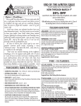
January 2003
Volume 5, No. 1
A Monthly Publication for GM Dealership Service Professionals
wheels at one time or another. This is
accomplished by attaching a transfer
case to the transmission output, to route
torque to both front and rear axles. Each
axle contains a differential to route torque
to right and left wheels.
Multi-wheel-drive systems fall into two
broad categories, determined by the kind
of transfer case used.
In all-wheel drive systems, the transfer case has only one speed or range.
4-wheel drive systems all contain a
transfer case that has two speeds, called
high range and low range.
As you will see, understanding the various features, characteristics and operating conditions is no longer a simple task.
Operating Characteristics
All-Wheel Drive
All-Wheel Drive and 4-Wheel Drive
General Motors offers a record number of vehicles that are driven by all
four wheels. You’ve probably heard
them called 4-wheel drive, 4x4s, allwheel drive, 4-wheelers, and possibly
others. But the components in these
systems are not all alike, their operating principles don’t work alike, and their
operating characteristics aren’t alike.
The following is intended to clear up
some of the confusion.
Definitions
All multi-wheel-drive systems are capable of providing engine torque to all four
Some all-wheel drive systems are
called on-demand. Torque is provided to
only one axle until its wheels slip. Then,
torque is also supplied to the other axle.
The decision of when to distribute torque
to the second axle, and how much, may
be made electronically or mechanically.
Another kind of all-wheel drive system
is called full-time. In these, torque is
supplied to both axles all the time, in various amounts. When wheels on one end
continued on page 2
Contents
All-Wheel Drive and 4-Wheel Drive . . . . . . . . . . .1
Know-How Broadcasts for February . . . . . . . . . . .2
4T65E Transaxle Conditions . . . . . . . . . . . . . . . .3
Engine Off Natural Vacuum Diagnostic . . . . . . . . .4
Transmission Oil Cooler Flush and Flow Testing Kit 6
Labor Time Guide Redesigned . . . . . . . . . . . . . . .6
Smoke Machine Revisited . . . . . . . . . . . . . . . . . .7
J-45059 Angle Meter . . . . . . . . . . . . . . . . . . . .7
Bulletins . . . . . . . . . . . . . . . . . . . . . . . . . . . . . .8
Vibe driveline is typical On-Demand
AWD system
Service and Parts Operations
1
continued from page 1
of the vehicle begin to slip, torque is
routed to the opposite end, where traction is still present.
Although operation of all-wheel drive
vehicles is mostly transparent, they can
make more noise and have more unusual
characteristics than 2-wheel drive systems. There are more parts rotating, and
more gears meshing.
When an on-demand system engages
the second axle, the occupants may hear
and feel the components working. The
driver may also be aware of sensations
and noises when making turns, even on
high-traction surfaces where the second
axle is not called on to operate.
4-Wheel Drive, Part Time
In part time 4-wheel drive systems,
torque is normally sent only to the rear
axle. When the driver chooses, the front
axle can also be engaged. Further, the
driver can select between high and low
ranges. Some part-time systems also
offer an Auto function that selects
between 2-wheel and 4-wheel drive
modes according to need, without the
driver having to do anything. Even in
these systems, however, the driver must
choose between high and low range.
on hard pavement, driveline binding can
cause the tires to “crow-hop,” which can
be heard and felt. This results because all
four of the tires do not rotate exactly the
same number of rpm, either side to side
or front to rear. Eventually, this difference
causes the driveline to begin to bind, or
”wind up,” and one tire or other must
temporarily break traction with the pavement to relieve the pent-up energy. On
unpaved surfaces, tires can slip as necessary to overcome binding, without causing crow-hop or noise.
Running the engine with the transfer
case in Neutral may result in noise, and
shifting into or out of Neutral can result
in some normal gear clash.
4-Wheel Drive, Full Time
The automatic 4-wheel drive system
provides torque to all four wheels all the
time, similar to the all-wheel drive system. But like other 4-wheel drive systems, it also has a low range. The driver
can select (depending on the model) 4
HI, 4HI Lock, 4 LO Lock, and neutral.
GM TechLink is a monthly magazine
for all GM retail technicians and
service consultants providing timely
information to help increase knowledge about GM products and
improve the performance of the
service department.
Manager, Product Readiness:
R. M. (Bob) Savo
GM Parts and Service Operations
[email protected]
Publisher & Editor:
Mark Stesney
GM Parts and Service Operations
[email protected]
Technical Editor:
Jim Horner
[email protected]
1-248-816-3641
Production Manager:
In a part-time system, the occupants
may feel or hear “something” when the
front axle engages. The transfer case
makes more noise in 4-high mode than in
2-high mode. And the extra gear reduc-
Marie Meredith
Desktop Publishing:
Greg Szpaichler, MediaWurks
[email protected]
FAX number:
1-248-649-5465
Typical full-time 4WD transfer case
4-Wheel Drive, Active
This system provides the driver with
five choices: 2 HI, Auto 4WD, 4 HI, 4 LO,
and neutral.
These vehicle can be driven continuously in Auto, although there is a fuel
economy and noise penalty.
Typical part-time 4WD transfer case
tion of 4-low mode is prone to making
even more noise.
Part time systems have no differential
or other device to allow front and rear
propshafts to turn at different rates. So, if
the vehicle is operated in 4-wheel mode
When driven in 4-HI or 4-LO, these
vehicles can experience crow hopping as
well. However, when driven in Auto, the
operation of the clutch pack compensates for different driveshaft speeds.
All Systems
Some noises in these vehicles aren’t
new -- they’ve been present in
Know-How Broadcasts for February
Emerging
Issues
February 12,
2003
Technology
Close-Up
February 27,
2003
9:00 AM, 12:30 PM,
3:30 PM EasternTime
9:00 AM, 12:30 PM,
3:30 PM EasternTime
Write to:
TechLink
PO Box 500
Troy, MI 48007-0500
GM TechLink on the Web:
http://service.gm.com
General Motors service tips are
intended for use by professional technicians, not a "do-it-yourselfer." They
are written to inform those technicians of conditions that may occur on
some vehicles, or to provide information that could assist in the proper
service of a vehicle. Properly trained
technicians have the equipment, tools,
safety instructions and know-how to
do a job properly and safely. If a condition is described, do not assume
that the bulletin applies to your vehicle or that your vehicle will have that
condition. See a General Motors dealer servicing your brand of General
Motors vehicle for information on
whether your vehicle may benefit from
the information.
Inclusion in this publication is not necessarily an endorsement of the individual or the company.
Copyright© 2003 General Motors Corporation
All rights reserved.
- Thanks to Tracy Timmerman
2
continued from page 2
unusual or typical is to operate a similar
vehicle under similar conditions.
It’s necessary to drive the vehicle
under conditions that duplicate the customer’s concern. Be sure to try all
ranges, in both 2- and 4-wheel drive.
Try the Auto range if equipped. Drive in
straight lines, and also in circles.
Typical active 4WD transfer case
4WD/AWD vehicles all
along. But today’s vehicles are made to operate
and ride more quietly, so
these normal noises and
sensations are more
noticeable.
One way to determine
if a noise or condition is
4T65E Transaxle
Conditions
Owners of 2003 vehicles equipped
with the 4T65E automatic transaxle (RPO
MN3, MN7, M15, and M76) may experi-
TIP: In part-time 4WD systems, it’s
important that all tires are the same circumference, to avoid driveline binding,
and the resulting crow-hopping. Tires
should be not only the same size but
also the same brand and type. This is
because circumferences can vary a little among brands and types. It may not
be much, but it can be enough to
cause problems. Proper and even tire
inflation is also extremely important
and frequently overlooked. And excessive wear of one tire can cause different circumferences.
- Thanks to BJ Lackey
Current Transfer Case Applications
ence harsh shift, TCC shudder during
decel, TCC applied in 2nd gear, and DTC
P0742. This may be caused by an internal failure of the PWM solenoid.
Determine the date code, located on
the electrical connector. Replace the
solenoid if the date is between 2217 and
2240. The suspect solenoid leaks
between the O-rings, shown.
Transmissions with build dates before
date code 254 (stamped on upper right
side of transmission tag) are considered
to contain the suspect PWM solenoids.
To determine if the solenoid is the
cause of the conditions, test drive the
vehicle with the Tech 2 connected and
monitor Transmission Release Pressure.
The status should be YES until TCC
applies, then the display should read NO.
Suspect the PWM solenoid if the status remains NO during accel, the
upshifts are harsh, and the vehicle shudders during downshifts during decel.
Another approach is to connect a Tech
2, shift to Drive range and manually
apply third gear with the Tech 2. If the
engine stumbles and/or stalls, suspect
the PWM solenoid.
Replace the PWM solenoid (item 334
in the 4T65E Technician’s Guide). The
current part number is 24214974, and
the Labor Operation Number is K6557.
IMPORTANT: Do not replace the valve
body if all valves appear to operate
freely.
- Thanks to Darryl Butler
3
With even a tiny pinhole in
the pop bottle or cap, this will
not occur because the leak
permits the pressure within
the bottle to equalize with the
air pressure around the bottle.
Engine Off
Natural Vacuum
Diagnostic
The EVAP system on a vehicle is
intended to prevent evaporated fuel
(vapor) in the fuel system from leaking
out into the atmosphere. According to
OBD II rules, the vehicle must perform
self-tests periodically to detect and indicate the presence of leaks. The present
standard requires being able to detect
leaks as small as 0.020-inch (0.51 mm).
The new Engine Off Natural Vacuum
(EONV) diagnostic system is used on the
following 2003 trucks with V6 and V8
engines:
- federal emission vehicles with GVW
of 8600 pounds (3900 kg) or less.
- California emission vehicles with
GVW of 14,000 pounds (6350 kg) or
less
What’s Different
About the EVAP
Hardware on EONV
Systems
Railway tanker collapsed
due to trapped vacuum
on an empty plastic soda pop bottle and
put it in the refrigerator. After a few minutes, look at the bottle.
As the air temperature in the bottle
drops, so does pressure, indicated by the
Previous leak detection methods were
performed with the engine running.
EONV monitors EVAP system pressure
or vacuum with the key off. So it may
take up to 40 minutes for the PCM to
power down.
For the applicable vehicles, the EONV
diagnostic replaces only the previous
small-leak detection method. All of the
other EVAP system component tests are
still used during engine operation. These
include large leak, restricted vent, excessive vacuum, and others.
TIP: This is important to remember
when performing a parasitic draw test on
vehicles equipped with EONV.
Then, after shutdown, the EONV test
runs, provided all of the engine-on tests
passed.
Operating Principles
EONV uses the natural pressure
changes in the fuel tank to detect leaks.
Pressure in a sealed container follows
temperature changes. That is, pressure
rises when temperature rises. Pressure
drops when temperature drops.
Actually, none of the hardware has changed. All of the
same plumbing, solenoids,
valves, and fuel tank
pressure/vacuum sensor are the same.
The software in the PCM has changed to
make the test run, and the canister vent
solenoid is wired to battery voltage
instead of Ignition 1.
Plain bottle, left, collapsed after
refrigerating, right
partial collapse of the bottle.
This is an oversimplified representation
of what happens to a fuel tank after shutdown when the fuel and tank cool down.
While a vehicle is driven, the fuel in
the tank is warmed, even on returnless
fuel systems, by warm air from the
engine, radiator and exhaust system.
Pressure increases in the fuel tank. This
is true even in cold ambient temperatures.
To avoid battery rundown, the diagnostic limits the number of tests run over a
specific period of time. When an EONV
test passes, the calibrated time between
tests is lengthened.
Step-by-Step Operation
Although the EONV test runs after
engine shutdown, the process actually
begins even before the engine is started.
That’s because the EONV test can be
enabled only after all other engine run-
After shutdown, pressure rises for
awhile, then eventually drops when the
fuel in the tank cools. The EONV system
uses the presence or absence of natural
pressure changes to detect leaks. If there
is even a tiny leak, the expected pressure
changes do not occur.
In the sealed system, a finite amount
of pressure or vacuum will be seen. With
a 0.020-inch (.51 mm) leak present, little
or no pressure or vacuum is observed.
Experiment
At room temperature, tighten the cap
EVAP system components unchanged
4
ning EVAP tests have run, which requires
a long cold-soak shutdown. For all practical purposes, this limits the EONV to
occur not more than once per day. A long
cold-soak meets these requirements:
diagnostic passes, meaning the
system is leak-free, and the test is
over. The pressure threshold is a
function of predicted ambient
temperature and fuel level.
- start up intake air temperature (IAT)
is between 39°-86°F (4°-30°C)
- If a vacuum occurs, the diagnostic
switches directly to vacuum testing
without bleed-down.
- start up engine coolant temperature
(ECT) is less than 86°F (30°C)
- start up IAT and ECT are within 15°F
(8°C) of each other
After startup, the following must also
be satisfied before EONV is enabled:
- ambient temperature must be
between 40° and 96°F (4° and 35°C).
For more information on this, see
Sub-Functions below.
- fuel level between 15% and
85% full
- engine run time, distance traveled,
and engine coolant temperature
must indicate that the system is
adequately warmed up
- certain DTCs not present. Refer to SI
for specifics.
There are three tests that make up the
EONV diagnostic: volatility, pressure, and
vacuum.
Volatility Test -- The EONV diagnostic
is very sensitive to large amounts of fuel
vaporization due to high volatility fuel.
The volatility test makes sure the vaporization rates will not negatively affect the
test results.
The EONV volatility test runs immediately after key-down if all the enable criteria have been met. The PCM monitors
pressure for a calibrated amount of time
with the canister vent open and uses preprogrammed values to predict fuel volatility. The logic behind this test is that if
pressure builds in the system with the
canister vent open, it will certainly be
able to mask a 0.020-inch (.51 mm) leak
with the vent closed.
If the test determines that the volatility
of the fuel is high, the PCM aborts the
diagnostic. If the fuel is moderately
volatile, the diagnostic runs, with compensation for volatility. For low fuel
volatility, the diagnostic runs without corrections.
Pressure Test -- The pressure test
begins by closing the canister vent solenoid and observing the pressure increase
inside the fuel tank. At this point, the fuel
is still warm enough for some amount of
vaporization to occur.
- If the pressure increase reaches the
calibrated pressure threshold, the
- If the pressure threshold is not
reached, the PCM records the peak
pressure that is reached, and adjusts
the vacuum threshold for the
vacuum test. Then, the PCM opens
the canister vent valve and waits for
system pressure to bleed down.
The pressure must decay a calibrated
amount from the peak pressure for the
PCM to consider it a peak, and switch to
the vacuum test. The adjusted vacuum
threshold equals the difference between
the pressure peak and the pressure
threshold.
Vacuum Test -- During vacuum testing, the PCM closes the canister vent
valve and monitors the tank vacuum to
determine if the vacuum threshold is
reached.
- If the vacuum threshold is reached,
indicating that the system can hold a
vacuum, the diagnostic passes, and
the test is complete.
not suffice. The PCM:
- Uses vehicle speed and airflow to
calculate an offset value, which is
subtracted from the intake air
temperature to predict ambient
temperature.
- Equates the estimated ambient
temperature to intake air
temperature for a calibrated amount
of time after a cold start.
Refueling Determination -- The PCM
looks for a net increase in fuel level over
the course of a test. The PCM also looks
for an abrupt change in vacuum over a
calibrated amount of time, as well as
changes in fuel level or system pressure
that indicate a refueling event. The PCM
detects refueling events only when the
vent is closed.
If a refueling event is detected, the
PCM aborts the diagnostic and opens the
canister vent. The canister vent must be
opened quickly to prevent the canister
vent from corking closed. Corking is a
condition when the canister vent solenoid is not opened quickly enough, causing pressure in the EVAP system to hold
the canister vent solenoid closed.
TIP: These individual test results cannot be displayed on the Tech 2. After at
least three successful completions, the
“pass” flag will display.
Rationality Test -- The rationality test
determines if the refueling detection was
caused by an intermittent signal, or an
actual refueling of the vehicle. During the
test, the PCM checks to see if the current fuel level is greater than the initial
fuel level for a calibrated amount of time.
If the calibrated amount of time passes
and the PCM is not able to determine
whether the fuel level is greater, the refueling event is declared irrational and a
DTC is set for the sensor that falsely
detected the refueling event.
Diagnostic Result
Other
The PCM quantifies the diagnostic
result, incorporating the results of the
pressure and vacuum tests. The current
result is compared with the previously
stored results. If this moves above the
fail threshold within the PCM, the MIL is
turned on and DTC P0442 is set, indicating a leak larger than 0.020-inch (.51
mm).
TIP: Because the PCM remains on during the EONV test, serial data may be
observed using the Tech 2. You can
watch the vent valve commands and the
values from the FTP sensor, for instance.
After the PCM completes the EONV test,
it powers down and serial data stops.
- If the vacuum threshold is not
reached, the PCM must compare
this with previously stored tests
before determining whether to call it
a “fail.” This is explained below.
Sub-Functions
The EONV system must perform several sub-functions to run the EONV diagnostic.
Determining Ambient Temperature - The EONV must estimate ambient
temperature. Because EONV occurs at
the end of the drive cycle, measuring
intake air temperature at start-up will
5
TIP: If a customer is going to take their
vehicle to an I/M inspection station after
service involving clearing DTCs, explain
that they should wait four days. The
EONV test usually runs only once per day
due to the cold-soak requirement. And
the I/M status bit “flag” will set
ready/complete only after at least three
successful completions.
- Thanks to Jack Woodward, Chad
Lehner and Jeff Kemph
Transmission Oil
Cooler Flush and
Flow Testing Kit
GM studies indicate that restricted transmission oil flow is detrimental to the life of any
automatic transmission. Plugged oil coolers and
oil cooler line restrictions cause insufficient
transmission lubrication and elevated operating
temperatures which can lead to premature
transmission failure. Many repeat repair cases
can be prevented by following published procedures for transmission oil cooler flushing and
flow checking.
J-45096 TransFlow is a transmission oil cooling system flusher and flow tester and will be
released in December.
A major advantage of this new tool is that it
uses conventional Dexron III automatic transmission fluid as the cleaning agent. Unlike earlier oil cooler flushing tools, it doesn’t use detergents, other chemical cleaning agents or hot
water, so there is no hazardous waste to dispose of.
The J-45096 TransFlow is installed in a
wheeled cabinet similar to the ACR 2000 airconditioning service station. It is equipped with:
- 32 quart oil supply vessel
- 34 quart waste oil vessel
- air pressure supply fitting
- digital flow rate indicator
J-45096-KIT. All of these
are itemized and illustrated in the User’s Manual.
Contact Kent-Moore at
1.800.345.2233 for additional information.
In the flush mode, air
pressure forces clean
transmission fluid
through the oil cooler and
lines. This removes dirty
oil and blockages. To
enhance the cleaning
action, the oil is agitated
with bursts of air. The
cooler is flushed first in the backflush direction,
then the normal flow direction.
Waste oil is collected in a built-in waste tank.
After flushing, use the digital flow rate indicator in the J-45096 to perform a flow test. The
User’s Manual includes minimum flow rate
charts.
TIP: Minimum flow rates vary, depending on
whether the oil cooler is made of aluminum or
steel. And the flow rates also vary with temperature. Be sure you determine both these facts
before performing the flow test.
The flow test indicates whether the oil cooler
and cooler lines still have restrictions, which
must be addressed before the repair is completed. If required, the TransFlow will provide an
encrypted 7-digit warranty code following the
flow test.
The entire flush and flow test procedure
takes only 5-8 minutes.
- 10-foot 12V DC power cable
- 10-foot black supply oil hose with quick connect fitting
- 10-foot clear waste oil hose with quick connect fitting
The TransFlow equipment is connected to
the vehicle’s transmission oil cooler lines using
the current cooler line adapters. Two adapters
are included with the TransFlow. Five other
adapters have been released in the past. And
three of the common ones are available in the
The waste tank can be emptied either using a
suction hose in the port provided or by draining
from the built-in drain fitting at the bottom of
the tank. In either case, the waste oil can be
disposed of the same as any other drained
transmission fluid.
Procedures in SI will be changed to accommodate the new J-45096 flush and flow tester.
- Thanks to Dan Popoff, Russ Dobson and Dave
Roland
The menu lists the operation categories
by letter and by name. If you are unsure of
the exact terminology or number, this is
probably the best way to conduct your
search. Simply click your choice. These
names follow SI terminology.
Labor Time Guide
Redesigned
INFORMATION FOR SERVICE MANAGERS AND WARRANTY ADMINISTRATORS IN THE US
EXAMPLE: J Engine
Effective February 1, 2003, the GM
Labor Time Guide will be redesigned. It will
now have the same overall appearance and
function as other GM service documents,
such as SI and owner’s manuals.
The new Labor Time Guide will be sent
to you on two CDs, one containing the
application and the other containing the
data.
In the future, you will receive updates
every second month (months with ‘even’
numbers, such as April, June, etc.).
Usage Tips
To use the new Labor Time Guide, you
must first “build” the vehicle in question.
This is done by using pulldown menus to
specify model year, make and model.
TransFlow
connectors
In most cases, the next screen presents
sub-categories within the broad category.
Again, click on your choice. These names
also follow SI terminology.
EXAMPLE: Engine Mechanical
EXAMPLE: 2003 Buick LeSabre
Click Next, then click Labor Time Guide.
You can now search for specific labor
operations three ways.
- By name, using common industry
nomenclature
- By number, if you know it
- By menu
Spaces are provided for you to type in
the name or number.
6
Within the sub-category, your search
results are arranged by 5-digit labor codes,
followed by the labor operation titles.
Click on your choice to see the operation
number along with the labor time associated with that number, expressed in hours
and tenths.
TIP: “Add times” are also displayed
when appropriate.
- Thanks to Terrie Nicholson and Lisa Scott
TIP: You may want to refer to the earlier article first. If necessary, you can find a
copy of it on the TechLink website at
http://service.gm.com.
The EEST was developed to help you
locate tiny leaks in the EVAP system,
which are defined by OBD 2 as 0.020inch (0.51 mm) or larger. It does this by
pressurizing the system with vaporized
mineral oil, which appears as smoke
when it escapes from a leak. The tool
includes a bright light to help you pinpoint the smoke.
The EEST is also equipped with a precision flowmeter, to help you determine
whether you’ve repaired the leak once
you’ve located and fixed it.
Using the Smoke Tester
Smoke Machine
Revisited
In the November 2002 issue we covered the operating principles and diagnostic tips for the EVAP system on the
Pontiac Vibe and Chevrolet Prizm. This
month, we’re covering the EONV system
used on some 2003 trucks.
So, it’s appropriate to revisit the
J-41413-200 Evaporative Emission
System Tester (the EEST, or “smoke
machine”) which we first covered in the
November 2001 issue. Here are some
additional pointers you may find useful.
J-45059 Angle Meter
The new essential J-45059 Angle
Meter has just been shipped to dealers.
It is used to ensure proper fastener tightness when using the torque-to-angle procedure.
The new meter is unlike earlier
torque/angle meters in several ways.
First, it does not require an anchor arm,
so it’s very convenient to use, even in
confined places. Second, it does not
measure the initial torque, just the final
angle. So you’ll use your normal torque
wrench, plus the angle meter.
A Brief Look at the
Science of Tightening
Fasteners
Friction is the resistance to relative
motion between two surfaces. It is present between the threads of a fastener
and the threads of a component, and
between the bolt head and the surface of
the component. When a threaded fastener is tightened with a wrench, up to 90%
of the torque applied to the fastener is
necessary to overcome friction. Only
about 10% of the force is used to hold
the components together. This is called
clamp load.
Fastener friction and clamp load can be
affected by thread cleanliness, thread
The EEST can be connected to the
EVAP system two places, depending on
instructions in SI. These are the underhood EVAP service port with the green
cap, and the fuel filler neck.
You can connect at the service port
without disturbing any fittings or connections in the system.
TIP: If the leak you’re looking for happens to be between the filler neck and
the filler cap, removing and replacing the
cap for testing could cause the leak to
disappear.
TIP: It’s recommended that the fuel
tank not be full before performing a
smoke test.
size, how often the fastener has been used, and
the fit of the wrench on
the bolt head.
Consistent clamp load
is always important, but
has taken on a new level
of concern in modern,
lightweight engine components. Ovetightening can
lead to distorted parts
(such as cylinder bores)
and undertightening can
lead to leaks and parts
coming loose.
Torque-to-Angle
It’s become fairly common to temporarily
assemble parts to the
proper clamp load before
machining them. For
instance, cylinder bores are machined
with bore plates bolted and torqued into
place on the engine block. Connecting
rod and crankshaft bearing bores are
machined with the caps torqued into
place. When these parts are assembled
in the plant, or reassembled in the service department after repair, it’s necessary to apply the same consistent torque
to the fasteners to ensure that the parts
assume their proper as-machined shapes.
When a bolt is tightened, it stretches a
7
This is because in some vehicles, the
fuel filler neck enters the tank from the
side. If the fuel is above this level, smoke
from the service port has to pass through
liquid fuel to reach the filler neck and cap.
Most or all of the smoke will dissolve in
the fuel and may not reach the filler area.
So to be sure you’ve tested everything in
the system for leaks, it may be necessary to “smoke” the system from both
the service port and from the filler neck.
Numerous filler neck adapters are supplied for this purpose.
Importance of Testing with
the Flowmeter
Many vehicles do not have an EVAP
service bay test to determine if an effective EVAP leak repair has been done. So,
the flowmeter in the EEST is the only
practical method to be sure you’ve actually located and repaired a small leak.
TIP: You will learn in the accompanying
article that the EONV small leak self-test
will not report a pass/fail until it has run
three successive small leak diagnostics.
This takes three days of operation, at the
very least. Again, use the flowmeter to
determine if you’ve made a proper repair.
With most systems, using the flowmeter is a good way to prevent comebacks. But with EONV, it’s impossible to
know you’ve made an effective repair by
any other means.
- Thanks to Jack Woodward
little. This is called elastic deformation. When
the bolt stretches, its
clamp load is very predictable.
When a bolt turns
one revolution, it
moves a distance equal
to the distance
between two adjacent
threads. For instance, a
bolt with 18 threads
per inch moves 1/18inch per revolution.
Engineers can determine the amount of
stretch a bolt needs, to
apply the proper clamp
load. This is related
directly to the amount
the bolt is turned, in
degrees. By specifying how far the bolt
has to be turned (measured in degrees),
after a preliminary torque is reached, the
engineers can precisely control clamp
load.
A typical cylinder head installation may
call for tightening the bolts in stages. For
instance on the L18 head bolts, first
torque to 30 Nm. On the second pass
verify 30 Nm and torque 120° in
sequence. On the third pass, depending
on bolt length:
continued on page 8
Bulletins - December 2002
This review of service bulletins released
through mid-December lists the bulletin number, superseded bulletin number (if applicable), subject and models.
ENGINE/PROPULSION
SYSTEM:
01-04-18-001A; replaces 01-04-18-001;
Driveline Characteristics for All-Wheel and
Four-Wheel Drive Systems; 2003 and Prior
LD Truck Models with AWD or 4WD
02-04-21-006A; replaces 02-04-21-006;
Inoperative 4WD/AWD Lamps or System;
2002-03 LD Trucks with Electronic Shift or
Active Transfer Case (RPO NP1, NP4, or
NP8)
02-06-01-022A; replaces 02-06-01-022;
Information on Engine Ticking; specified LD
Trucks 2002-03 with 6.6L Duramax Diesel
Engine (VIN 1 -- RPO LB7)
02-06-03-012; Proper Diagnostic
Procedures for No Start, No Crank, Battery,
Generator, Gauges, SES, SIR, Brake
Security, Theft, ABS, Hot, DIC Messages,
Lamp, Light, Diagnostic Testing; 1997-2003
Passenger Cars, LD Trucks, Hummer H2
02-06-04-026A; replaces 02-06-04-026;
Engine Backfire and Related Driveability
Issues; 1999-2002 Chevrolet and GMC B7
School Bus and C6-7 Conventional Cab MD
Models with 7.4L or 8.1L Engine (VINs B, E
-- RPOs L21, L18) and IMPCO/Quantum
Technologies LPG Fuel System
02-06-04-052; Engine Stalls, No Start,
Hard Start (Repair Fuel Pump Feed Circuit);
1990-2002 Chevrolet and GMC H6-7 CSeries MD with Gas Engine
02-06-04-053; Revised DTC P0403
Exhaust Gas Recirculation (EGR) Solenoid
Control Circuit; 2000 Chevrolet Venture,
Oldsmobile Silhouette, Pontiac Montana
with 3.4L Engine (VIN E -- RPO LA1)
02-06-04-055; Vehicle is Difficult to Fill
with Fuel (Install Fuel Filler Baffle); 2003
Chevrolet Express, GMC Savana, Except
with Left Side Door and Cutaway, Cube and
Cab-Chassis
02-06-05-005; Exhaust/Muffler Heat
Shield Rattle, Popping Noise Under Vehicle
(Install Heat Shield Retaining Straps on
Muffler); 2002 Cadillac Escalade, GMC
Denali with 5.3L or 6.0L Gas Engine (VINs
T, N -- RPOs LM7, LQ9)
BRAKES:
TRANSMISSION/TRANSAXLE:
02-05-22-004B; replaces 02-05-22-004;
Trailer Brakes Applied When
Headlights/Park Lamps Are On, Brake
Controller Illumination (Modify Brake
Controller Wiring Harness) specified 200203 LD Trucks and Hummer H2
02-05-27-001A; replaces 02-05-27-001;
Antilock Brake System (ABS) Indicator
Illuminates When Power Takeoff (PTO) is
Engaged (Replace Electronic Brake Control
Module EBCM); specified 2001-02
Chevrolet and GMC Trucks with Air Antilock
Brakes (RPO JE5) and Allison Auto
Transmission
02-07-30-032A; replaces 02-07-30-032;
Allison Transmission Control Module
FastLearn Procedure Update Required After
Transmission Repairs; 2002-03 Chevrolet
Silverado, GMC Sierra with Allison 1000
Series Automatic Transmission
02-07-30-040; Difficult Shifting from Park
to Drive Range (Replace Shift Indicator
Slide within Floor Console); 2001-02 Pontiac
Aztek
02-07-30-042; Allison Transmission
Service Repairs; specified 2003 Chevrolet
Kodiak and GMC TopKick models with
Allison 1000-2400 Series Transmission
GENERAL INFORMATION:
99-00-89-015B; replaces 99-00-89-015A;
Light Service Support Vehicle (LSSV); 19992003 Chevrolet Silverado, Suburban, Tahoe
4WD Models with Military Upfit
HVAC:
02-01-39-007; Automatic Dual Zone
HVAC Battery Draw; 2003 LD Trucks and
Hummer H2
STEERING:
02-02-32-012; Rattle/Knock Noise When
Turning While Driving Over Rough Roads
(No Fix at This Time, Fix Under
Development); 1999-2002 Chevrolet
Cavalier, Pontiac Sunfire
SUSPENSION:
01-03-10-012A; replaces 01-03-10-012;
Guidelines for Using E2020 Wheel
Alignments, E2000 Toe Adjust and E0200,
E0201, E0203, E0204 Wheel Balance; 19892003 Passenger Cars and LD Trucks, 2003
Hummer H2
DRIVELINE AXLE:
02-07-30-043; Allison Transmission
Service Repairs; 2001-03 Chevrolet
Silverado and GMC Sierra HD 2500 and
3500 with Allison 1000 Series Auto
Transmission (RPO M74)
02-7-30-048; Pressure Control Solenoid
Replacement for 4T65-E, 4T40-E and 4T45E Transaxle/Transmission; specified 2000-03
vehicles with RPO Codes MN4, MN5, M13,
M15, MN3, MN7 OR M76
BODY AND ACCESSORIES:
02-08-42-005; Snowplow Roof Beacon
(Lamp) Inoperative (Install Bypass Harness);
2003 Chevrolet Silverado, Suburban, Tahoe,
GMC Sierra, Yukon, XL with Snow Plow
Provision (RPO VYU) and Roof Mounted
Lamp Provisions (RPO TRW/5G4)
02-08-44-018; Diagnostic Information for
No Audio Out of Speakers on One or More
Channels; 2003 Cadillac Escalade, Chevrolet
Silverado, Suburban, Tahoe, GMC Sierra,
Yukon, XL, Hummer H2 with Premium
Bose Sound Systems
02-08-46-010A; replaces 02-08-46-010;
Programming OnStar Module for Canadian
French Voice Recognition; specified 2003
Passenger Cars, LD Trucks, Hummer H2,
with OnStar
02-08-48-001; Stationary Glass Urethane
Adhesives -- Additional Materials
Recognized; 2003 and prior Passenger Cars
and Trucks, 2003 Hummer H2
02-08-49-004A; replaces 02-08-49-004;
Instrument Panel Cluster (IPC) Gauges
Read Zero at Times, Gauges Inop at Times
(Reprogram (PC); 2002 Chevrolet TrailBlazer,
EXT, GMC Envoy, XL, Oldsmobile Bravada
02-08-63-003; Bumper Fascia Cover
Retainers Pulling Out of Fascia (Trim
Fascia); 2002-03 Chevrolet Avalanche
02-08-64-022; Cycling Power Folding
Mirror to Remain in Locked Position After
Transport; 2003 LD Trucks with Power
Folding Exterior Mirror (RPO DL3), Hummer
H2 with Power Folding Exterior Mirror (RPO
DL7)
02-08-110-006; Revised Sunshade
Replacement; 2002-03 Chevrolet TrailBlazer,
EXT, GMC Envoy, XL, Oldsmobile Bravada
02-08-127-001; Availability of Rear
Parking Assist Sensor Service Harness;
2001-03 Chevrolet Venture, Oldsmobile
Silhouette, Pontiac Montana
J-45059 Angle Meter from page 7
- tighten bolts 1, 2, 3, 6, 7, 8, 9, 10,
11, 14, 16, 17, an additional 60°
- tighten bolts 15 and 18, an
additional 45°
- tighten bolts 4, 5, 12, 13, an
additional 30°
Measuring the tightening in degrees is
the purpose of the J-45059 Angle Meter.
Using the J-45059 Angle
Meter
These are the highlights. Refer to the
instructions that come with the meter for
full details.
The J-45059 Angle Meter is designed
for use with a standard 1/2-inch drive
extension and a ratchet or torque
wrench.
TIP: The bolt must already
be tightened to the specified
initial torque before final
angle-tightening.
Begin by turning the
meter on; the last-set value
will display. Use the
up/down arrows to set the
display to the desired angle
value. The range is 0-199° in
1° increments.
Attach the meter to the
1/2-inch extension, as close
as practical to the socket,
8
using the spring-loaded clamp.
Install the socket to the bolt. Without
turning the bolt, apply pressure in the
direction of tightening to remove
all free play from the wrench.
Then press the On/Zero button
and hold until the meter sounds a
short beep and flashes.
Tighten the bolt. When the preset angle is reached, the meter
sounds a long beep and flashes.
After use, the meter will shut
itself off within a minute to conserve battery power.
- Thanks to Tracy Flood and Ron
Minoletti