1
BabyWarmer
ServicemanualKANMED
ServiceManual
o
KANMED
BABYWARMER
Partno: BW-50-079
/ 58
C(
0413
Modifications
Any modlffcationson the control unit, control unit eledronics, heating pad, water mattressand baby nest
wlllvold K.rrl'IMED's
resoonsibilitiestotallv and are not allowedwithout the written consentof KANMED.
Caution
Pleas€readthls manualcarefully-Incorrectuseand serviceof patientwarmingequipmentmaycause
serlouspatientinjury.
CONTENTS
1
4
5
6
7
PAGE
Introduction
Principlesof operation
SparePartsand exchangeunits
Dismantling-Reassembling
Procedures
Repairing,
Troubleshooting,
TemDerature
measurement
Softwareinformation
WiringDiagram
Manufaduredby:
KANT1ED
AB
GArdsfogdevSgen
188
SE-16866 Bromma
Sweden
Tel: +46 8 564 80 630
Fax:+46 I 564 80 639
www.KANMED.se
2005-03-24
Page'l of I
BabYWamet
SeNicemanualKANIVIED
1 INTRODUCTION
BabyWarmer and how to verify thEt it is functioninqproperlywe
For a generaldescriptionof the KANIYED
from internetin several
referto the usermanuat.ln aua"yo, oo not i,uveone it can be downloaded
Se www KANI\4ED.se
lanquaqes.
basrcfunctionsof the KANMEDBabywarmer and how do determinefaults
d".*i;ile
i;i: .:,il;"';i;t
and do smallerrepairs
and qualifiedHospital
technicians
servicepolicvstatesthat only properlytraineddistributor
KANIYED's
PcB
the
main
on
may carryour repajrs
technicians
ensuresthe deljveryof a
i^ii""ij *" ".t'v", ti makeiull use of our PcB exchangeprogram becausethis
warranty'
PCBwith 3 months
replacement
testedand calibrated
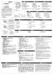
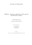
2 PRINCIPLE OF OPERATION
SeealsodiagramPage3 and 9
waterbedfor infants
controlled
BabyWarmeris an elect callyheatedand precision
The KAN14ED
pocket
in th€ water mattress
into
a
pad,
is
inserted,
which
tt consistsof a control unit and a heating
power-switchesPS1and PS2'
via
unit/
control
lv
ttre
p"a
is-suppiied
r'"iting
ii;tr!;i];;
fi;;;$"
T1, T2 and 13
ir'r" n""ii"g i"d *"t"i"s the helting elementRLandthermistors
of the
T3 sensesthe temperature
while
mattress
in
the
i.:n." tf'" t"mperatureofihe water
illnaiz
heatingelementin the Pad.
PS1to limit the element
Usingthe informationaboutelementtemperaturesuppliedby T3, the CPIJcontrols.
selectedtemperature,
the
lower
than
is
temp-eiatureto alout +3oc as long as the actual water temperature
temperatureis
the
set
when
and
mattress
in
the
water
of the
via T1 the cPU monitorsthe temperarure
reached,the CPUcontrolsPS1to keep the water temperatureat the set value ,
psz ina"p"ndent from the cPU and if for 'ome reasonthe temperatureof the water exceeds
fi."nfloit
the beeperand the overternp
39oC,T2 will switchoff PS2and stopthe heatingaltogetherand alsoactivate
'LED,
t l r . e . - w a t c h d o g m o n i t o r s c P U o p e r a t i o n a n d i n c a s_e o f a c P l J f a i | s r e s w i t c h e s o f f h e a t i n g V i a t h e s a
SS and also;ctivatesthe beeperand the eledronicfailure LED'
is used to sto.e calibrationvaluesfor T1 and T3 input circuits'
The EEPRO14
or DCvoltaqe12 - 24 v
tne iuppty voltageto the controlunit can eitherbe mainsvoltage115/ 230 V AC
but the first choiceof the unit will alwaysbe the
simultaneously
aotn iupptyvbttaq"scan be connected
by
the oN/oFF switch or is not presentat start up'
."i". ri'prjrv. Ii ihe main disappears,is switchedolf
to
unit
DC
supply
RE1will closeand connectthe
"safety logic".andall safeiy circuitsare
ni"".n tiitt of tf'" *"rming, the CPUissuesa test signalto the
the cPU continueto
i".iJ au|"ingtf'" .o .ulled ;elf test. only if all tests aie successfullycompletedcan
oDerateand startthe warmjng,
Page2 of I
BabyWarmer
ServicemanualKANI\lED
Fig.l BLOCKDIAGRAMKBW50
t /
"q"4
t l
\
\
Et I
ii
z,
o\
r
i
I
_ z S{rl
@o@@
Page3 of 8
tr
BabYwarmer
ServicemanualKANMED
3 SPARE PARTSAND EXCHANGEUNITS
3.1 SPARE PARTS POLICY
keepsand suppliesspare parts considerednecessaryto keep a good servicelevel
KANII4ED
Theseare to be found in the spare part list.
of
must not b€ replacedunlessyou havethe possibility
WARNING: Certaincomponents
carefully
5
2
REPAIRING
ca|rying out a calibrationof the unit. Study section
oeforecarryingo.lt any PCBrepairs.
3.2 EXCHANGE POLICY
and
runsan exchangeseruicefor the 14ain_
and keeprepairtime low, KANMED
To simplifyrepairprocedur€s
FrontPcBof the KBw50.
Designation
MainPCBKBW50, Exch.Unit
FrontPCBKBW50,Exch.lJnit
Exchange part No.
700-0234-EU
700-0235-EU
ExchangelJnitswi||besUppliedatafixedprice(marked:''repairprice''onthespar-e-partspriceIi
priceis-equiva|enttotheestimatedaveragerepaircost)independentofthetypeoffau|tiftheretur
faultyPCBis foundto be repairable.
For returnedfaulty PCBSwhich are found not to be repairable,we offer you to buy an Exchangeunit at a
"sellingprice"on the sparcpartspricelist).
specialprice(marked
w!ll
an extrachargeto coverthe costof the missingcomponents
For returnedPcB,swhichare cannibalised,
Pice.
be addedto the Exchange
3.3 SPAREPARTLIST (SP
too-4267
700-0234
700-o234EU
700-o234EU
700-0280
7AO-0324
700 0242
700-0260
700-0259
700-0269
700"0233
700-0001
700-oo79
too-o232
7AO-0244
100-o279
700-027t
700-0268
7AO-O235
100-0264
700-o272
700 0230
700 0253
100-0274
700-0255
700-0459
700-0231
BW-50-07x
1
1
1
1
Bottom Dlate
IVIAiNPCB KBW50
l4ainPCBKBW50(repairprice)
MainPCBKgW 50 (sellPrice)
HousinoKBW50
FuseT3.15A
KBW50
PROIVI
Grcundcableassv.l.BW50
GroundcableKBW50
Batterv LR6.alkaline
1
10
1
1
1
1
1
10
10
1
FuseT1A 1250V
FuseT 2A 1250V
14ains
inletand fllter
sLud
equalisation
Potential
RearDanelKBW50with label
cableassv.7-poolKBW50
Handle
Front PCBKBW50
FrontDanelKBW50,with label
KBW50
Cableassy.3-pol
1
1
1
1
1
1
1
1
E d q ec o v e l
LiqhterPluq
3ooleDIN Dluq{battervcable)
Elastoseal
22uF,50v 105'C
Cagacitor
Transformer
'
'net
from inte
user manualscan be downloaded
Page4of8
Seruice
manualKANI\IED
BabvWarmer
4 DISMANTLING AND REASSEMBLINGPROCEDURES
wARluNG:
CAUTION:
Alwaysdlsconnectthe mainscable beforeopeningthe Instrument,
Work only on properlygroundedstatic free working stationsfollowingESDrules.
The following proceduresare descrlbedbelow :
4.1 SOTTOMPLATE
4.2 RUBBER
EDGECOVERS
4.3 MAINPCB
4.4 FRONT/ REARPANEL
4,5 FRONT
PCB
4,6 HANDLE
4,I BOTTOM PLATE
.
.
.
Placethe instrumentupsidedown
Removethe 6 screws
Slidethe bottom plate towardsthe front panel until it comesfree from the rear edge cover and then
lift off the bottom plate and disconnectthe ground wlre, Don't forget to reconnectthe ground wire or
it may causeshort cuts.
4.2 RUBBER EDGE COVER:;
Edgecoversare only removedlf you have to exchangefront or rcar panels.
Edgecovers are glued ( ELASTOSEAL
A07, se SPL)to the housingbut not to the bottom plate.
1 Breakthe bondingof the glue from the 3 sidesof the housingby applylngforce and if nessecarycut with a
to replacethe runneredge.
thin bladewithoutdamagingthe painting.Sometimesit will be nessecary
2 Grip the edge cover in a corner and lift it a few mm to free the insidegrooveof the cover from the
protrudingpart of the front oe rear panel and pull the cover from the housing
REllOUNTING:Apply a thin layer of ELASTOSEAL
A07 on that part of the housingthat
will be coveredby the edge cover before mounting the edge cover,
4.3 MAIN PCB
1. Dismountthe bottom plate
2. DisconnedconnectorsP1, P4, P5 and P6 (se paqe 12). NoTE: when dlsconnecting/ conneding P1.
support the PCBin order to avold heavy bendingwhich will damagecomponents.
3, Removethe 4 pcs PcB-mountingscrews
4, Grip the PcB by the battery holder and relaysand pull the PCBtowardsthe rear panel until sockets
JZ8 come free from pins PZ8 on the front panel and then lift the PCBout from the housing
4.4 FROI{T AND REAR PANEL
1. Dismountthe edge cover accordingto procedure4.2
2, Disconnectthe Danelto be removedfrom the l\4ainPCB
3. Removethe 4 screwsthat flt the panelto the housingand then pull off the panelfrom the housing
and disconnect
th€ groundwire
Page c or d
BabYwamet
SeNicemanualKANI\,4ED
4.5 FRONT PCB
1. Removethe front panel accordingto procedure4.4
2. Removethe 2 nutsandthen pulloff the PCBfrom the panel
4.5 HANDLE
(Phillips)
throughthe holein the handleand unscrewthe screws
Threada screwdriver
NOTEr]f for some reasonthe handleis not remounted,the mounting holesfor screwsmust be fitted with
lvl5screws(max. length 25 mm) to prevent liquid from enteringthe unit
5 REPAIRING,
5.1 GENERAL
usingproper
electronic
engineers
Troubleshootingand repairingshouldonly be carriedout by experienced
and circuitdiagramsprovidedin this manual
to descriptions
toolsand test equipmentand with reference
measurement
See Doint6 abouttemDerature
PCBSERVICE
we recommendto use our EXCHANGE
5.2 WARNINGS AND CAUTIONS
amplifierN4.connectorP1and
WARNING WhenevervoltagerequlatorN7, operational
associatedcomponentsare replacedor re-soldered,the KBW50has to be calibrated
cando this.
according
to section7. OnlyKANMED
WARNING Whenoperatingthe KBW50with the bottomplateremoved,AC voltagehigherthan 300 v will
be exposed,Take precautionsto avoid electricalshocks.
WARNING Evenafter disconnectinglvlainsPowerfrom the unit, capacitorsmay still carry
voltages.Take care to avoid electricalshocks,
cAuTIoN
The KBW5ocontainsstatic sensitiveClllos deviceswhich mav be damagedby improper
stations
handling,Do not handleexcepton properlygroundedstaticfree working
Handleall PrintedCircuitBoards(PCB)by thelr edles, do not touchany partsunnecessarily.
packing
CAUTION All PCB'S
sentbackfor repai.or exchangemust be properlypackedin conductive
materialorthey will not be repaired!l
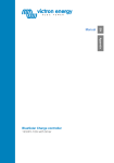
6 TEMPERATUREMEASURING
EouiDment
needed:
Precision
thermometerwith skinsensor
A foam mattress about 50 mm thick
Standardhospitalbaby blanket
1. Placethe heating pad in the pocketof the water mattrcss and put it on the foam mattress
2. Tape the skin sensoron the top centre ol the water mattress and cover with the blanket There
must be water and no air bubblesin the water mattress,(l\4akesure there is very good contact
betweenthe sensorand the water mattressto avoid false readinqs)
3, Start the heating with and note the temperatureof the water mattr€ssabout 10 min after the set
temperaturehas beenreached
4. The recorded temperature should be "set temperatu16" +/- 0.soc
'
Page6of8
BabYWarmer
SeryicemanualKANMED
- 0'soc
)
:i,?i'ii[:i:f,[":;1H?-"j,x.":il]?3,"J,"i'j"'e,s
L
+r
lirnltatlonr
ternperature
T1
r2
Element
T3
@
@
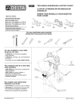
Note: The T1, T2 and T3
To obtain absolut€ tru€
20
27
22
KO
12,492
11,942
i-e-p"rat,,e"c
2A
29
36
8.4083
7,/2r.t
23
24
25
26
27
imperature'c
Tcozo
37
38
39
40
7,0983
6.8082
6,5314
10,000
9,5722
KA
6,2675
6 , 0r 5 5
5,175r
5,1170
7 SOFTWAREINFORMATION
;:il?l'3l.""'":lii['"?',",.{rui,i:{1,'i"1"'$TJi!ir
pi6r'4veisioninaicationtales plac:irr-:Y:l
or a remp!L- " '- lows'
of 5 flickering
consrsLs
FlicleringtemP_LEU
25
30
34
Software History
p*outu".r'on
1.A2
1_03
1.04
Versionsexlsr:
Up to now the followlngSoftware
Sw,version Issued
9635
v1.02
96 47
v1.03
v1.04
98 39
serles
1 : groduction
hcorooratesTl / T3 tesnng
allV1 02 PROM5
ReDlaces
acaeotsnew calibration box
sens;s 12l24 V external bafierY
lmProvedsafetY
Page 7 of I
ComPatibilitY
allV1,02and V1 03
replaces
BabYWamer
manualKANMED
Seruice
8. Wiring Diagram
Fig.t3 Wlrlngdiagdm
Page I of I