1
[;] = &l ~
j ~ -=
Whirlpool
ConsumerEurope
Services
AVM 870
PHILIPS e
~
Whirlpool
Service
Manual
MICROWAVE
Combi
A VM 870
Model
AVM 870 stainl
Version
853887001081
.,
Introduction, safety
481271490015
Technical data
481271450039
TexVLegend
481271450038
Spare parts list
4812 71480163
Exploded view
4812 714 60032
Exploded view
4812 714 60052
Exploded view
4812 714 60053
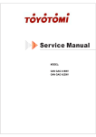
Wiring diagram
481271470035
This documentation
is only intended
9ulations.
Date: 25.08.1993
Document-No.: 481271410155
Register Nr.:
tor qualified
technicians
who are aware of the respective
safety
re-
Subject to modification
(~
:. .., ~~ ~.
~~ i- ~~ ~'f" ~.
Whirlpool
Europe
~.
\\'Iurl(lool
Consumer
Services
481271490015
INTRODUCTION
Before leaving the factory each oven is carefully
It must however, be installed and used correctly.
checked.
Despite all the steps laken to make the oven safe, the safety is dependent
understands
how to use and maintain the oven.
on the correct
installation
and the fact the user
The information
in this section should be used as areminder
thai the oven is safe and thai anyone who uses it must first
read the instructions
tor use in order to be able to use the oven correctly and obtain the best results.
SAFETY
To avoid
injury to yourself
.Always
If there
.When
the internal
servicing
connections
an oven before
wires are insulated
-all
the earth connections
are electrically
-do
not modify
interfere
-MICROWAVE
and not touching
or anyway
sure thai each
not start arepair
CAUTION
always
work to the following
rules
when servicing
an oven.
you reconnect
it to the mains,
make sure thai:
are correct
-the
-make
.00
to the appliance
disconnect
the plug tram the mains before starting work.
is no plug switch-off the electricity supply at the control box.
you have finished
-all
and damage
replacement
the door,or
the cabinet
and mechanically
sharp
sound
with the safety devices
built-in
part you use conforms
if you have any doubt as to your ability
or anything
to the oven
to the manufacturer's
to complete
specifications
it.
RADIATION
PERSONNEL
SHOULD
NOT BE EXPOSED TO THE MICROWAVE
ENERGY WHICH MAY RADIATE FROM THE
MAGNETRON,
WAVEGUIDE OR ANTENNA IF THEY ARE IMPROPERL Y USED OR CONNECTED. ALL INPUT AND OUTPUT MICROWAVE CONNECTIONS,
WAVEGUIDES,
FLANGES AND GASKETS MUST BE SECURE.
NEVER OPERATE THE DEVICE WITHOUT A MICROWAVE ENERGY ABSORBING LOAD ATTACHED.
NEVER LOOK INTO AN OPEN WAVEGUIDE OR ANTEN NA WHILE THE DEVICE IS ENERGIZED.
NEVER OPERATE AN OVEN WITH CABINET OFF WITHOUT MEASURING
THE MICROWAVE
LEAKAGE AROUND
MAGNETRON
AND VISIBLE MICROWAVE CONNECTIONS
(WELDING JOINTS).
00 not operate
the oven if the following
conditions
exist:
-The
doof does not close firmly against the dOOf support
-The
dOOf trims
-If
there
-If
the dOOf does
is any visible
-HIGH
of the dOOf being warped
or the hinges damaged.
or seals are damaged.
damage
not close
to the oven.
properly.
Avoid operating the oven if known components
known defective. They must be replaced.
WARNING
because
in the interlock
system,
oven dOOf or microwave
generating
assembly
are
VOLTAGE
IT IS POSSIBLETO
COME IN CONTACTWITH
LETHAL HIGH VaL TAGE WHEN WORKING WITH HVTRANSFORMER,
HV
CAPACITOR, AND MAGNETRON.
THEREFORE NEVER TRY TO MEASURE THE HIGH VOLTAGE. ALWAYS TAKE UTMOST CARE WHEN PERFORMING
ELECTRIC MEASUREMENTS
INSIDE THE OVEN.
Technical data
4812 714 50039
-~
2.
PHYSICAL REQUIREMENT
2.1
Electrical
Measured at l1nambient tempoof25°C , 230V and 1 liter load
Operating voltage:
Performance within spec.:
Test voltage (safety requirements):
2.1.1
207-244V
210-244V
207-244Y
Rated Input Voltage:
(HD 270 SI)
207-244V (230Y)
216-254V (240V)
2.1.2
Rated frequency:
50 Hz
2.1.3
Phases:
Single phase
2.1.4
Rated Input Power:
-MWO:
2.1.5
Rated Input Current:
-MWO:
-Blower, lamp,
mains filter + el.nik:
3200W cold oven
3100Wafter 10 min operation
14.5A cold oven
13.5A after 10 min operation
0.7A
2.1.6
Peak current:
Max. 20A with duration of <3 ms
Max. 40A with a duration of<10 ms
2.1.7
Fuse:
Germany
UK
CH+DK
S
lnternal Fuse rnarking:
TI OA Special
MW Output Power:
1700W::!::10%
(acc. to IEC 705)
(without any utensils in the cavity)
MW Power regulation:
Switching on/off. + cycling
Cycle time 40 S.
4 levels available, 1700W, 850W, 425W
continuos and 200W
Timer:
15 min.
Tirner accuracy:
See functional requirements
2.1.8
2.1.9
.2.1.10
2.1.11
!:
.,
1
"
16A (D, PH)
35A (S, PH)
16A (D, PH)
16A (D, PH)
, .
',;)
,-
~~
~---~
-~
---
--~-JjJii
Technical data
2.1.12
Mains cord:
4812 71450039
All cords fit with receptacles für connection to
mains filter. No plug für wall socket.
2.1.13
Mains filter:
Separatelyapproved by SEV Of VDE and
SEMKO.
2.1.14
HT -capacitor:
Separatelyapproved in Germany
2.1.15
Cavity tamp:
Long life 2000 hrs halogen lamp, 240V 10W
Not replaceableby customer.
2.1.16
Radio interference::
See Quality requirements
2.1.17
Microwave teakage:
See Quality requirements
2.1.18
[mmunity:
2.1.19
-Asymmetrical
Low energy pulses
Medium energy pulses
High energy pulses
1.25kV
1.25kV
1.25kV.
-Symmetrical
Low energy pulses
Medium energy pulses
High energy pulses
1.0kV
1.0kV
1.0kV
Mains interruption:
10ms
«10 ms no star
> 10 ms no damage)
2.1.20
ESD:
15Kv(150pF/150Q)
cr SPECrFICA
~
TION: ~~~.
A Vj'
f\ [",jasretom
92~O9-29
DA Norl'köping AB
'
~---~
""
853887001081
Sh: 190
,
,~
---""
f;;;~t~C
() (19)
Technical data
2.2
Mechanical
2_2.1
Physical properties
Weight:
4812 71450039
Gross 66.0 kg
Net
61.5 kg
Out er dimensions:
597x662x468/518 (WxDxH) height depending
on mounting ofbottom runners)
Dept without handle (mm):
628
Cavity dimensions
535x348x201 (37.4 1)
535x348x 187 (34.8 I)
gross:
net:
Door opening:
505x20 I
Box dimension, package:
785x699x630
Built in dimension:
595x450
,.
Box dimension, package:
625x405x485
!!
Max. allowed G-force on
product:
tl
,
I 1\',
40g
I
.
, .-,
d.:.J!:o 1:
I
0:-':
\11.'>
df.
!
COITIls,n\'1 rest
'()()21
I
---~-I,'I(~/'\ "frON:
';:,("1
Name:
)
Or. date.
~
'.,'
879
.i.
Ci tilge date:
92-09
f"frAD.", !'~r.rrköp ir
A VM
',.-,.188'7() '-.108,
~-'
'
,cl.:;;
,--~
,--
4812 71450038
PRO-2000 ProfessionalMicrowave Ovens FUNCTIONAL DESCRlPllON
1.
Power On
2.
Short Form Cooking Instmction
2.1
2.2
2.3
2.4
3.
Programming Mode
3:1
4.
ProgrammingStarted
Diagnostic Mode
4.1
4.2
4.3
4.4
4.5
4.6
4.7
4.8
4.9
5.
Manual Setting
Memory Cooking
Multiply Function
CookingFinished
Total CookingTime
Nurnberof Door Openings ;a
Numberof Starts
Fault Codes
BuzzerVolume
Key Beep
Disabling of Manual Timer
Option NurnberDisplay
RealTime Setting
Test Mode
5.1
5.2 -5.27
5.28
5.29
5.30
EnterTestMode
Various Tests
Programmingthe EEPROMto FactoryDefault Values
FactoryDefaultValues
Output Power
6.
Cooking Time Table
7.
Time Out
8.
Multiple Portions
4812 71450038
1
PowerOn
At power on the ovenwill normallygo to standby, and a ":" will bedisplayed.
Programming,diagnostic,and testmodeare alsoenteredwhen poweris switchedon.
If power is tumed on while
2.
the POWERl and the PROGR3
buttonsare pressed
The ovenenteIs programmingmode. A "P"
is displayed
the PROGR3and the PROGR7
buttonsare pressed
The ovenenteIsdiagnosticmode. A "d" is
displayed
the dOOfis openand the STOP
buttonsis pressed
The ovenenterstestmode.
Shor1Form Cooking Instruction
Whenthe ovenis in standby, time will bedisplayedif the real time clock is set,otherwise
":" \\111be displayed.Cookingcan be startedeithermanually, or by loadingtime and
,.
power from memory.
2.1
Manual Setting
To settime and power manually,follow thesesteps:
*
Setthe desiredtime by tuming the timeTknob. Time will be setaccordingto the
cookingtime table (seeunder 5), and the maximumtime is 15 min. Powerwill be set
to the highestlevel, and will be indicatedby a blinking LED. The lamp and fan will
be tumed on.
*
Powermay now be setto required level by pressinga POWERbutton.
*
If the dOOfis closed,the ovenmay now be startedby pressingthe START-button.
Whenthe ovenis cooking,the powerLED is continuouslyon.
*
Time and powercan not bechangedwhile the ovenis running.
*
If cookingis interruptedby openingthe door, the powerLED will startblinking.
Time and power may now bechanged.
When cookingis finished,the ovenreepsthree times and the display startsblinking.
Blinking stopsafter 30 seconds,or if the dOOfis opened.The lamp and fall are on für 30
secondsafter finished cooking.
2.2
Memory Cooking
To startcooking by loadingtime and powerfrom apresetmemory,follow thesesteps:
* Pressthe desiredPROGRAMbutton. Time and power will be loadedfrom memory
and displayed.The power LED will be continuouslyon, and the prograrnLED will be
blinking.
*
Releasethe PROGRAMbutton. Ifthe dOOfis closed,the ovenwill now start cooking.
481271450038
If cooking has beeninterruptedby openingthe door,the LED indicating the selected
program will startblinking. The oven may be startedagain in Olleof the following ways
after closing the door:
* Pressthe start button. Ifmore than Olleitem offood has beenselected(see2.3 below)
the total nurnberof items will be displayedfür 1.5 seconds.The ovenwill startcooking
again "ith the displayedtime and power.
* Pressthe button at the blinking LED and releaseit againimmediately.The ovenwill
start cooking again with the displayedtime and power.
* Pressthe button at the blinking LED and hold it für 3 seconds.time and powerwill
again be loadedfrom memory,and whenthe buttonis releasedthe oven will start
cooking.
*
Pressany other PROGRAMbutton. Time and power will be loadedfrom memory,and
whenthe button is releasedthe ovenwill startcooking.
2.3
Multigly Function
Cooking time that has beenloadedfrom memorymay berecalculatedfür more than olle
item of food.
:..
* Pressthe selectedPROGRAM buttonwhile the ovenis cooking. For eachtime the
button is pressed,the time für Ollemore item of food will beaddedto the cooking time.
The total numberof items will bedisplayedfür 1.5secondsafter the button is released.
* The total nurnberof iternsrnay becheckedby pressingany other button exceptfür the
STOPbutton.
*
If the oven is startedby the START button after interruption, the total numberof items
will bedisplayedfür 1.5 seconds.
The numberof items is limited to 8, and it is also restrictedby the maximum total cooking
time. Whenthe numberof portion is lirnited, this will beindicatedby 5 shortbeeps.
2.4 Cookingfinished
After finished cooking, the ovenbeeps3 times, and the display startsblinking. The
blinking stopsafter 30 seconds,or if the door is opened,whichevercomesfirst.
481271450038
3
Programming Mode
When prograrnmingmodehas beenentereda "P" is displayed.As soonas the manual
timeTknob is turned,cookingtime will be displayed,and the power level will be setto 3
(highestpowerlevel).
If the STOPbutton is pressed,or if 30 secondshavepassedwithout any operation,the
oven will go to normal operation.
3.1
PrograrnmingStarted
If the ovenis in programmingmode,and time and poweris displayedand
4
the TllvffiR-knob is turned
clockwise
The cookingtime will be incrementedin
stepsaccordingto the cookingtime table (see
under 5)
the TllvffiR-knob is turned anticlockwise
The cooking time will bedecrementedin
stepsaccordingto the cooking time table.
a POWER buttonis pressed
The powerlevel will beset,and indicatedby
':k a blinking LED.
a PROGRAMbutton is pressed
If cookingtime is displayed,time and power
will be storedin the selectedmemory.
Storageis confirmed by 4 shortreeps.
the START buttonis pressed
No action
the STOPbuttonis pressed
The ovenleavesprogrammingmodeand is
readytor operation.
Diagnostic Mode
Whenthe diagnosticmodehas beenentereda "d" is displayed.Ifthe STOPbutton is
pressed,or if 30 secondshavepassedwithout any operation.the ovenwill go to normal
operation.
4.1
Total cooking time
If the POWER 3 button is pressed,the total cookingtime is displayed.The largestnumber
of hours that can be recordedis 9999. When poweris turnedoff, thesedataare stored in
the non-volatile memory.
4.2
NumberofDoor o~nings
If the POWER2 button is pressed,the total numberof dOOfopeningsdivided by tell is
displayed(e.g. 753 is displayedas 75). The largest numberof dOOfopeningsthat can be
recordedis 99999. Whenpower is turned off, thesedataare storedin non-volatile
memory.
4.3
Number of Starts
If the POWER 1 button is pressed,the total numberof startsdivided by tell is displayed
(e.g. 753 is displayedas 75). The largestnumberof startsthat can be recordedis 99999.
Whenpower is turned off, thesedataare stored in the non-volatilememory.
481271450038
4.4
Fault Codes
If the DEFROSTbutton is pressed,the latestfault codeis displayed.The fault codesare
listed in the servicemanual.
4.5
BuzzerVolume
If the PROGRAM I button is pressed,the buzzeris setto high volume.
If the PROGRAM1 button is pressedagain,the buzzeris setto low volume.
4.6
K~ BeeR
If the PROGRAM 2 buttonis pressed,key beepis tumed on.
If the PROGRAM 2 buttonis pressedagain, key beepis tumedoff..
4.7
EnablingfDisablingofManual Timer
If the PROGRAM3 button is pressed,the manualtimeTis enabled.
If the PROGRAM3 button is pressedagain,the manualtimeTis disabled.
4.8
ÜDtion NumberDimlav
If the PROGRAM5 buttonis pressed,the option numberis displayed.The option number
dependson the versionof the oven (maximumMW power)and is setby diodeson the
control board.The availableoptionsare describedin the servicemanual.
4.9
Real Time Setting
A real time clock is available.It can only be used,however,ifthe ovenis alwaystumed
on. The clock must be seteverytime powerhas beentumed off.
If the PROGRAM 8 buttonis pressed,the colon will be displayed,and the hoursdigits
will startblinking.
The hours may now be setby turning the timeTknob.
Whenthe PROGRAM 8 button is pressedagain, the minuteswill startblinking.
The minutesmay now be setby turning the timeTknob.
Whenthe PROGRAM 8 button is pressedagain, the ovenwill displaya "d".
Whenthe stopbutton is pressed,the ovengoesto normaloperatingmode.
4812
4.10
714 50038
Faultcodes
EO
EI
E2
E3
E4
ES
E6
E7
No fault
Relay 1010 cannot be syncronized
Relay 1009 cannot be syncronized
Write to EEPROM was unsuccessful
Relay 1010 short-circuited
Relay 1010 interrupted
Relay 1009 short-circuited
Relay 1009 interrupted
When pressing PROGRAM 5 a code will tell what oven type the control card is intended foT:
Code:
01
02
03
04
05
06
A VM
A VM
A VM
A VM
A VM
A VM
880 with current transformer
880 without current transformer
870 with current transformer
870 without current transformer
860 with current transformer
860 without current transformer
Diagnostic mode is terrninated by pressing the STOP b\i\ton
5.0
Test Mode
The microprocessor also contains a test program which will test the most vital microprocessor functions and the
function of the Fm display.
5.1
Enter Test Mode:
If power is turned on while the dOOfis open and the STOP button is pressed, the oven will enter Test
Mode. The display will show '88:88' and all LEDs are lit.
5.11
The dOOfis closed.
Everything is turned off.
5.12
Turn the timeT knob clockwise.
The LED foT program 3 is lit. The buzzer beeps.
'8t is shown in the first display digit.
5.13
Turn the firner knob anti-clockwise.
The LED foT program 5 is lit. The buzzer remains silent.
'8' is shown in the 3rd display digit. The fan/lamp relay
is activated.
5.14
Push POWER 3 foT minimum 0.5 sec.
The LED foT power 3 is lit. The buzzer beeps. The
illumination of the cavity is lit. The fan starts. '8' is shown
in the display digit 3.
5.15
Push POWER 2
The LED foT power 2 is lit. Ifthe fan/lamp have been
switched-off foT about 5 sec., the relay foT power level will
be activated. '8' will be shown in the display digit 2.
5.16
Push POWER 1
The LED foT power 1 is lit. The left main relay will be
activated (1009). '8' will be shown in the display digit 1.
5.17
Push DEFROST
The LED foT defrost is lit. The left pre-magnetizing relay
will be activated. (1007). '8' will be shown in the display
digit 4.
~I
\
4812 71450038
5.18
PushPROGRAM 1
The LED for program1 is Iit. The fight maiß relay will be
activated(1010). '8' will be shownin the display digit 3.
5.19
PushPROGRAM2
The LED for program2 is lit.. The fight pre-magnetizing
relay will be activated(1008). '8' will be shownin the
display digit 2.
5.20
PushPROGRAM3
The LED for program3 is lit. The buzzerbeepsweakly.
'8' is shownin the display digit 1.
5.21
PushPROGRAM4
The LED for program4 is lit. The buzzerwill beeploud. '
'8' is shownin the displaydigit 4.
5.22
PushPROGRAM5
The LED for program5 is lit. The fan/cavity lamp will be
activated.'8' will be shownin the display digit 3
5.23
PushPROGRAM6
The LED for program6 is lit.. The relay for power level
(1006) will beactivated.'8' is shownin the display digit 1.
5.24
PushPROGRAM 7
The LED for program 7 is lit. The left main relay will be
activated(1009). '8' is shownin the displaydigit 1.
5.25
PushPROGRAM 8
The LED for program8 is lit. The left pre-magnetizing
relay will beactivated.(1007). '8' will be shownin the
displaydigit 4.
5.26
PushSTART
The fight maiß relay will be activated.(1010). '8' will be
shownin the displaydigit 3.
5.27
PushSTOP
The testmodeis terminated.
5.28
Programming the EEPROM to factory default values:
While being in testmodepush consecutivelySTART -POWER 3 -PROGRAM 4 in row. Within 5
sec.the EEPROMis the programmedinto factory defauitvalues.If the programmingwas successful,
the LED for power1 is lit and the buzzerwill reep 9 times.
5.29
Factorydefauitvalues:
The following combinationsof time and power are the defauitvaluespre-programmedin the
EEPROM
A VM 860
A VM 870
A VM 880
Power3:
Power3:
Power3:
Power3:
Power3:
Power3:
Power3:
Power3:
Power3:
Power3:
Power3:
Power3:
Power3:
Power3:
Power3:
Power3:
Power3:
Power3:
Power3:
Power3:
Power3:
Power2:
Power2:
Power2:
Program
1
2
3
4
5
6
7
8
0' 30"
0' 50"
l' 15"
0' 30"
l' 45"
2'15"
2' 45"
3' 30"
0' 25"
0' 30"
0' 50"
l' 00"
I' 15"
1'30"
2' 00"
2' 30"
0' 30"
0' 50"
I' 00"
I' 30"
1'45"
0'30"
I' 15"
I' 30",
4812 714 50038
5.30
6.
OutputPower
A VM 860
A VM 870
A VM 880
Power3:
Power2:
Power1:
Defrost:
Power3: 1700W
Power2: 850 W
Power1: 425 W
Defrost: 200 W
Power3: 2100 W
Power2: 1050W
Power1: 525 W
Defrost: 200 W
1300W
650 W
425 W
200 W
Cooking Time Table
The following timer incrementscan be usedin manualcooking or whenprogramming:
From
To
Increment
5 sec
3 min
5 min
8 min
12 min
3min
5 min
8 min
12 min
15 min
5 sec
10 sec
15 sec
30 sec
60 sec
~
7.
Time Out
If the door is left open,the fan and lamp will be switchedoff after 10 minutes.
8.
Multiple Portions
The maximumprogrammablenumberfor multiple portions is 8
J
4812 71450038
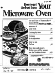
Positioning of the microwave stirrers.
If the drive chain for any reasonis taken off, changed or adjusted, it is most important that the
two microwave stirrers are placed in the position as indicated below:
Left waveguide
cv
Right waveguide
.@
Note the position of the split pins holding the stirrers in position
r~
-.-1 lWJ
ra =
~:. ..1
"'J
~
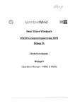
Model
Service
Version
Whirlpool
Customer
Europe
Services
A VM 870/stainl
853887001081
8538 870 01081
No.
Pos. No.
12 NC Code
Description
from
0020
002 1
011 0
0240
041 0
4819440 59528
4819 440 59526
4819 462 79586
481931088485
481940478053
Cabinet
Cover
Foot
Panel, rear
Hinge (Balance arm)
081 0
1000
111 0
1200
130 0
481946248382
4819440 59532
481949858459
481945948558
4819 464 18113
Shod< absorber
Door cpl. AVM 870
Grip door
Frame
Bearing microswitsches
130 1
130 2
130 3
1304
141 0
481946238676
4819 492 68657
4819 404 78544
481940478545
481945069529
Bearing
Spring
Bracket
Hoop
Inner glass
1430
2002
200 3
2004
2510
481945948563
4822 480 40112
4819 528 78071
481946298656
481938118151
Door frame outer AVM 870
Filter ,air
Wheel
Spring
Lampglass
255 0
2551
2560
3200
320 1
481941878842
481946278511
481941849579
481945349369
4819 453 49368
Piste, bottom
Bracket
Cap,protect.
Panel,control cpl.
Panel,control
3202
320 3
322 0
3221
334 0
481946418114
4819 404 78547
481946698749
481946698748
481941258288
Bracket
Bracket
Display chart
Recipe guide
Knob,timeswitch
3520
355 0
404 0
404 1
4042
481921478381
4819 280 18019
4819 131 58025
4819 310 88184
481946698747
Display
Buzzer
Magnetron
Air guide
Plate
4043
4060
4061
4062
411 0
481946238674
4819 361 18321
481940478539
482252231184
4819 148 68059
Guide,wave
Motor Antenna
Plate,mounting
Nut
Transformer
411 1
4120
412 1
4122
4200
4819 148 68062
4819148 68061
4819 404 78543
4819440 59527
481912148018
Transformer
Transformer HT
Bracket
Gap
Capacitor HT
421 0
4260
4420
4421
4422
4819 121 18162
481921838038
481936118133
481931088086
481945828005
Filter ,mains
Diode HV
Motor FAN
Plate,mounting
Grille
4423
4429
490 0
5020
502 1
481940478541
481951528166
4819 321 18207
481921478385
4819 209 88026
Bracket
Cabinet
Cable,mains SA
Board,printed Control AVM 870
Microprocessor
to
.
460032.-:,c,."
4062
721 3
~
~
4061
7211
721 2
-"\.c;>
'721O---,,~
721 7
721 6
490 0
.--J
6--.\\ ~
f,
6500
""
~
651 0
8501
~
& 404O
~
"&
(~:~ '
~~~:====~--- 6502
~""""""'
2510
-6 50 4 I
~~~" ~,
406
0020
7215
721 4
~~~
~
~
024 0
""",""rr->~""'"
;&1 0
562~
I
4041
4042 11/
611 0 ~
9010
0
-442
2551
~
~
~
'\.
~
4210
121
4421
120
442
081 0
002
5212
~,
1302
-130 0
~32 0
4111
122
/r=
2004
011 0
/
2002
'4260
~
""
~~
442
!
2550
1303
1304
2560
521
6170
~
@ ~ :.I
I
~
352 0
1::1
~ q'
3203
3201
i
~
t
4110
4422
5020
9720
3550
I
5211
5021
;:
~
502
I-"1\ %
~ ,
::~--""':~-
0 41
0
3
141 0
3202
1200
1430
322
~
~
621 0
r
3221
c
3340
,
,!,,:i.._;,-
1000
3200
1110
14812
714 80032]
r~
r. -l lYj
ra =
~~ ..1
~'j
~
Model
Service
Version
Whirlpool
Customer
Europe
Services
A VM 870/stainl
853887001081
8538 870 01081
No.
Pos. No.
12 NC Code
Description
5023
521 0
521 1
521 2
5213
481910148072
481921478382
4819 464 18112
4819 111 88002
481911388001
Potentiometer
Board,printed power
Bracket PCB
Combination,RC
Resistor 100 Ohm
521 4
561 D
562 0
5621
6110
4819 112 48023
481928248207
4819 282 48202
481928248261
481928068242
Resistor
Thermostat
Thermostat 95 C
Thermostat 100C
Relay
6111
6170
621 0
632 0
650 0
481928068316
4819280 28005
4819 277 18061
4819 271 38161
481925518184
Relay
Relay 48V
Power switch
Microswitch
Base,lamp
650
650
650
651
721
1
2
4
0
0
481940478546
4819380 28007
4819 492 68507
4819 134 48281
481951528051
Bracket
Reflector
Spring, cavity lamp
Lamp oven
Antenna
721 1
7212
721 3
721 4
7215
4822522 31178
4819535 98354
4822 358 50052
4819 492 38063
481941738109
Wheel
Shaft
Belt,driving
Spring
Hoop
721 6
721 7
901 0
971 0
9720
4822522 31177
4819 462 78677
4819 401 18135
4819 253 38021
481925338006
Wheel,chain
Cover piste
Clamp,cable
Fuse T1 DA
Fuse T100mA
--
trom
-
to
r~
-.l
~:. ..1
~.J
ra =
""~
Whirlpool Europe
Gustomer Services
Model
Service No.
Version
A VM 870/stainl
853887001081
8538 870 01081
Pos. No.
12 NC Code
Description
483
483
484
484
484
1
2
1
2
3
4819 320 58201
481932058206
4819 320 58199
4819 320 58202
481932058203
Gable
Gable
Gable
Gable
Gable
harness
harness
harness
harness
harness
484
484
484
484
484
4
5
6
7
8
4819 320 58204
4819 320 58205
481932058207
4819 320 58208
481932118208
Gable
Gable
Gable
Gable
Gable
harness
harness
harness
harness
harness
484 9
4819 321 18209
Gable harness
from
to
.-
460052
r~
~
=
.l
~WJ
81 "'J
I
ral
~.
.Whirlpool
Europe
Gustomer Services
Model
Service No.
Version
AVM 870/stainl
853887001081
8538 870 01081
Pos. No.
12 NC Code
Description
4851
4852
485 3
485 4
485 5
481932028015
481932028016
4819 320 28017
4819 320 28018
481932028019
Gable HT
Gable HT
Gable HT
Gable HT
Gable HT
485 6
485 7
4819 320 28021
481932028022
Gable HT
Gable HT
trom
to
.
460053
---
ElE:
8O
483 1
~
1
4
._~
::::::~~~~7~~§02
2
3
,:
13
~J===r;/
~.
~
~IO
.
01~===~~::::::~~
483 2
(I
-2
~~41
('
4
.~
~.'
~3
-10
484 1_~"';;:~~:::::=:==,",,8
.4
84 2-ES:"'o;~~::~====
=7'
484 3-8"""~~::::===,
484 4
~
~ci""""",
Rod -8
~
484 5-
Rod~
1:3~
~
,--~~ =;;::-
Yol'ow
2
484 6-§:;
-"~~::::::::::::::
484 7==-~~~
=?
Y.uo.
~
484 8~
:§
~(:§
Y"'ow
~. .YoI'ow
-'ö;~S~;~~~~
[-~
;:-
Y.llow
..
Y"'ow
4849_~_~
~~
,,~~~~
4812 714 60052
-g
~~I~
120ft
/F=======,~
~
~~
E5~
I~
~
//1
2o0tt.
4853,
k'
24L~::::::::~8
4854~
g ~ ,
k:
I~
~
../F=========ti
[60
~
i@;
~,
k=
400t~
~6~~
~k
32Lr::::::::::j~
~
~-
"
I~
/F=======~
~
--~
I/I
300""
~~
;;.1
4812 714 60053
,
,
I
1
I
I
I
~
Ö
0'
~
..,
-J
CD
---I
~IO
r~
CD
~
~
~
~
I-
0
...>-
--I
~.CI
~
~
~
0),
,
...I
~~
(:1
!!;
,
,
'
,
'
.,
~
..-
Ll)
'"
~
0
0
..-
I
1
I",.
I
I
~
1
I
I
~
>:
'
'
,
'
"', ,
0,
I
I
<0
I
I
I
, ,
,
'->-.;>
"'"
~~Q.
'I
~
~
.t:
ro
E
ro
...
CI
,:1:
:
,
0
'"
0
<,;;
on
Q;
:'->-.;>9:'"
r-~'
1.- 0-
.CI
C-'
"
(/)
~
~
X
X
~
.11
Q)
E
:0
~
-6
-ttn
"
11
""""""
000""
ddd
"""(1)
~
N
<
loJ
C-'
loJ
"""(1)
000""""
(/)~Q.
L4J0a:
0
-~
oZ-'
000:
ZI-<
<0:>-
&(/)
(/)1-1-
~oo
.~
,
,00:
0:,
1-,
Z,
0
0'
:
,~
I~:I::I:
I
I
:
,
~
0
0'
0:,
1
'C\J
~
-I'
,
I
I
;"->1.
I
'Q.
I "-'"
,-~
T
~T
,<
'0
(0,
-~
~
I
1
1
1o
~L4JOW
::>::>~::>z
z<
IoJ"&:ZC-'(/)Zo:=>Z
-,-'<=>_::>-L4J<
::><-'00:0:0-'0:
0
CD(/)
.O"'CDO:C-'EI)ZCDO
~
W
0
W
0
0
~
::!!::OL4JO<=>
0:
~~L4J
0
loJ~i~g~ffiffi~
0
3
~
O~!;:O>-O:-'-IO:
O>-~O:C-'CDCDEI)O
0:
=>
>-i5L4J~
OujWOO:O:O-lO:
C-'~O:C-'EI)(/)CDO
0
OL4JL4J
CD
01
Q.
~
.,
.
...loJ
~
~
@
~:I:(/)(/)
<,
0,
::::
@@
e
@
@@O
/"2>'l1ö;\
\;:;11.::;1
~
Q.
m
~)-G>Q.
"
, w
'"
--_J
'gl-
~~
-I-t-0
~)-G>
~
IZ
IW
IfI
~
CD
I-
CI
c:
>-
~
:c
.:I
.fO
o
C\J
~
0
~
...ja:
Ga.
1\
---~~
0
~
~
Q~G
~o
a.o
Ine@
J
, CD
'0:
t
~
,
,
,
0
~
~0:
0:
0
(\j
a
CD
:_~
>(:1
~0
>-
'J:
~
m
Co
..(:1
I"
1-
1<i5
10
IC\J
I
I
IZ
I>
0
10
11{)...
CD
0
>-
(:1
>-
~
I
I
"0'
:..,"'-'"
~
-J
CD
I
I
i=°
~
Cj5'VJ~:f;
I--I~I-«:I:«
)(
0
I
I
~
I
I
0:
°3:I:(/)
Q.o
I
I
I
I
I
o~
ZO
-0
Z
~~
~~
v,
,~
'0
:Q.
,
""
0
''0
,
.:I
~
I-
-'
I
1
-' ,
I
C\J I
~~
0:0:
o~~::>
I-
LJ..
"'I'""'
91
I
Z
~
01
~
g~
Z
< lJ.J
~:I:
~o:
~g
1oJ
0 ~
0" LU
~
-I