1
iz8)~
NocrdzeeWind
Near Shore Windpark
WbrlWm vergunningaanvraag NSW
Bijlage VI:
- Onderhoudsplan -
Bijlage 11
Operation Manual- NM80 & NM92
Near Shore Windpark
WbrlWm vergunningaanvraag NSW
Bijlage VI:
- Onderhoudsplan Bijlage 11
Operation Manual - NM80 & NM92
Document opgemaakt ten behoeve van WbrlWm vergunningaanvraag Near Shore
Windpark.
Opgemaakt door:
Aangeboden aan:
NoordzeeWind consortium
Ministerie van Verkeer en Waterstaat
Directoraat-Generaal Rijkswaterstaat
Bestaande uit:
Directie Noordzee
Shell Wind Energy BV
NV NUON Duurzame Energie
2288 BC RIJSWIJK
Postbus 5807
2280 HV RIJSWIJK
Koopmansstraat 1
Rev. Datum:
Status:
o 18-03-03
1 16-06-03
Concept; voor commentaar
Definitief; voor vergunningaanvraag
s/'d I.O:)!1i ~3N Ai: iom: (S
99 EOO,9ll :JU
l6HN/o8HN
lernU!lA UO!:ieJado
~1H:;MlCON'
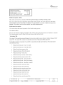
Preface and Revision
This operating manual relates to tbe NM80/2750 & NM92/2750 On-shore
The manual is the wind turbine generator owner's and operating manager's "vade mecum". Jt contains
safety and operalIng instructions, together with a general description of the wind turbine generator's
layout and design. Tt also describes thc possible error situalIons and how to reset the control system and
resume operations. This manual provides together with the Service Manual information on the service
maintenanee of lhe plani, to enable the owner or operator to lake care of it and ensure tbat at all times the
wind turbine generator is operalIng safely and eorrectly.
The manual is subject to revision based on eurrent experience. Tbis will maintain oplImum performance
and availability. The revision control system is described in the following..
icing
The contents ofthe manual and the procedures in it have been generated by NEGM's R&D and Serv
Departments and prepared in eonsultalIon with suppliers and in accordanee with approving authorities'
recommendations and requirements. NEGM (TIC) urges users oftbis manual to forward any suggestions
for correclIons or improveinents so that these ean be incorporated in the next revision.
Manufacturer:
NEG Mieon AIS
Alsvej 21
8900 Randers
www.neg-micon.dk
--
.._.~......._....__._"----_.._.-
RevIsion
Date
Description of changes
OL
24-10-2002
New document
------
02
03
i
TIC 726'003 GB
Date: 24-01.2003
~.._.._._~.._._._....._-
Page
Operation Manual- NMBO & NM92
Editor: PKR/MBN
2 of 59
,õ,pproval sign: MBN
I
..~-_._....._..~.-
~ii-GMlCON'
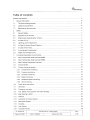
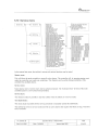
Table of content!:
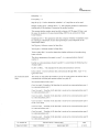
Preface and Revision ...... ..... . . ...... ....... ....... ................ .... 2
1 Generallnformation .............. .......... ................ ....... .......... .. .........6
1.1 The wind turbine generator.. ........... ...... .... ............. ................ . ......... ..6
1.2 Liability and guarantee .. ........ .... ........ ......... ....... ..... ...... ...6
1.3 Maintenance and servicing .. ........... .......................... .................... . ..... ..... .......6
2 Safety.......... ..................... ..... . .......... . ....... ............7
2.1 General Safety.. ................... ........ ....... . .. ........ .... 7
2.2 Approach to the Turbine ............ ..... ........ ....... ......... ..... .........7
2.3 Entering and Ascending the Turbine.... ......... ........... ...7
2.4 In Case of Fire.. ........... ........... .. ......8
2.5 Lightning and thunderstorms.. ....... ...................... ......... ........... ...8
2.6 In Case of Unusual Sound Patterns ..... ............. . ....8
2.7 In Case of Run Away ................ ............ . . ...... . ................... ...... ....... ....9
2.8 In the Nacelle Compartment ....................... ....... . . ........... ........... ..9
2.9 Safety and emergency line.... ........ ....... . ...... .............. .......... .. .........9
3 Functional Description of wind turbine.. .. ......... .......... ........... .............. ....... .... 11
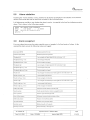
3.1 Wind Turbine Main Data Overview NM80 ................... ............. ....... .......11
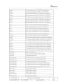
3.2 Wind Turbine Main Data Overview NM92... . ........... ........... .....11
3.3 Wind Turbine Component Overview . ...... .................. .......... ..12
3.4 Control System.. ........ .... ........... .............. .................. ......13
3.5 Turbine monitoring system.. ............. ......... ....15
3.5.1 Temperature monitoring ....... ........ .... ..... ............ ......... .............. .......15
3.5.2 Pressure monitoring. ....... .... . ........ ........ ....16
3.5.3 Humidity monitoring ................. .... ....................... .. ...... ........... . .....16
3.5.4 Slade monitoring .............. ..... .......16
3.5.5 Rotational speed monitoring.. . .. ........ . ......... ....... ........ .....16
3.5.6 Grid monitoring.... ............. ......................... . ............... .... ..........17
3.6 Power drive and control... . ....... ..........19
3.7 Generator ........ . ...... ............................ .......... ......20
3.8 Frequency converter.. ........ ..... .. ......20
3.9 Hub, Slades, Rotor System and Srake Strategy.. ...................... .....21
3.1' Gearbox.. ........ ......24
3.10 Main Searing & Shaft. . . . .. ............... ........23
3.12 Lubrication & Cooling System ... . .....26
3.13 Disc Brake System ... ............27
3.14 Coupling . .. ...... . ..... ................. ........... ................ ...27
3.15 Yaw System.... . ...... ..... .. ....................... . ...28
3.16 Controller Panels.. . ...................... ........ ..29
TIC 726'003 GB
Date: 24-01-2003
Operation Manual - NM80 & NM92
Editor: PKR/MBN
Approva! sign: MBN
--a-;
~~~
~N-(al,i:coN'
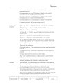
3.16.1 Main panel in tower .................... . . ........ ......... .........30
3.16.2 Operation panel (part off main panel) .................. ..... ...... . ......... ......30
1.1.1 Frequency converter panel in tower ........... ................ .. ....... . . ..... . ................. ...30
1.1.2 Control panel in nacelle.... .... ..... .......................... . ................................ ...31
1.1.3 Controller panels in rotor hub. .............. ......... ......................... .... .................. . ... ..31
3.17 Machine Base Frame, Sub Frame & Nacelle Cover ... .......... .. ..... ......... ..32
3.18 T ower & foundation............................ ............. ................. .. ... ......33
3.19 Lightning protection ............ ........ ................ . . ..... . ........... ................................. ..... .34
3.19.1 Total concept for lightning protection of wind turbine.. ...... .... .......... .. ..... ..34
3.19.2 Overvoltage protection of components in lightning protection zone 2.. . ......... ... ....... ....34
3.19.3 Overvoltage protection of components in Iightning protection zone 1.. . ..... ..34
3.19.4 Overvoltage protection of wind measurement equipment in zone OE.. . ............. ..35
3.19.5 Measurement report and documentation ...... ........ ............ .. ........... .. ..35
3.19.6 Blade protection ........... ....... .............. ........ .. ....... . . ....35
3.19.7 Blade tuming system .... ........ ....... ............ . ...... ......... .. ..... . ....................... ......... 35
3.19.8 Spinner and transmission system.. ....... ..................... .. ...... .... ....... .. ....35
3.19.9 Main bearing.. ...................... ..........35
3.19.10 Gear. .... ............... ...... ...... .......... . .........35
3.19.11 Nacelle.... ....... ....... . ..... ...... .... .............................. .35
3.19.12 Yawing system... ......... ... ...... ..36
3.19.13 Tower ........ ................ .................... .......... ............ ......36
3.19.14 Earthing system ......... ......... ......................... .......... ....36
3.19.15 Medium voltage plant. .. ... ............ .......... . ... ................................ ......36
3.19.16 Control system ............. . ....... ............. ...................... .......36
4 Operation of controller.. .................... ............. .................. . ....... 38
4.1 Keyboard .. ........... ............ . ............... .. ............... .................. . . ..........38
4.2 Display.. . ........... ......... . .......39
4.3 Operator panel.... ... .... ..... ...... ........ ...... ... ............. ........ ... ..... . ... ..39
4.3.1 Panel configuration.. . . . ........... ................ . .............. . ... .39
4.4 Operation box ... ... ......... ......... ... .... ... ........... ......41
4.4.1 Emergency switch. . . . . ........... ... ...41
4.4.2 Yaw switch.. .....1
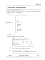
5 Description of menu system ................ . ............................... .....2
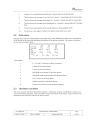
5.1 Status menu. . ................. ..... . .......42
5.2 Grid menu.. ..... .... ..... .43
5.3 Operation counters ......... . ........ ... ........................................ . .....43
5.4 User parameters.. . . ............ ...... ........ .... ..5
5.4.1 Set user parameter.. .. .... ................................... ....... .... .. ... ............... ... .....46
5.4.2 Set date/time. .......... .....46
5.4.3 Set communication protocol.. . ........... .....46
TIC 726'003 GB Operation Manual - NM80 & NM92 pa~
Date: 24-01-2003 _.. ~.. Editor: PKR/MBN Approval sign: MBN _~._.....__... ~ 4 o~_.J
~E-GMlÇON'
5.5 Temperature menu ........................... ..... ...... . ............................. ........... ..........9
5.6 Pressure menu.. ..... ... ...... ...... ........... ...... ........... .... ...... . . . ..... . .....50
5.7 Alarm log ...... ..................... . . . ... ................ ....... . . ............ .....................50
5.8 Alarm statistics ... ........... ..... . .............. .............................. .51
5.9 Alarm snapshot ...................... ............. . . ............. ......... . ....... ....... ... ......51
5.10 Service menu ......... ............. ..... .................... ...... .. ... ......... .........55
5.10.1 Minlmaxregister..... ..................................... ....... ..... ......... .......................57
5.10.2 InpuUOutput.... ................ .............. ....... .. ...57
5.10.3 Operation counters ... .......... . . . . .................... ...... ............................. ..............57
5.10.4 Wind sensors.. . .. . ... ............... . ..................... ............... . ... .................... .....57
5.10.5 Softare versions ....
........ .. ...... ..........57
5106 wrG setup..... .
..58
59
Appendix....
Main specification NM80 ..
.... .........59
.............. ...59
Main specification NM92 .
Operatìon Mamial- NM80 & NM92
TIC 726'003 GB
Date: 24-01-2003
Approval sign: MBN
Editor: PKR/MBN
_.__.~_._-"._...
I
Pa~
5 of
--
~
~lN::MlCON"
1 General Information
1.1 The wind turbine generator
An NEGM wind turbine generator is a meehanical plant functioning as a power station and supplying
electricity to the electrieity grid. Tt is vital for safeiy that tbc planl is hand
led correetly and in aecordance
with this manual. Compliance with tbe manual's rules and inslructions will ensure the plant a long service
life and the minimum operating and maintenance eosts.
NEGM's operating and control manual must be read earefully before operating the eontrol system,
mounting the tower or maintaining the plant. The safeiy regulations deseribed in the next cbaptber must
also be read and followed scrupulously.
1.2 liability and guanmtee
The turbine owner has general responsibility tor the operation and safety oflhe plant and must prevent all
risks of the grid being brought down by its operation, NOimally the owner will cooperate with NEGM's
Servicing Deparment over this, on the basis of a Servicing Contract.
lf major renovation work or the replacement of large parts is to be carried out after the expiry of the
guarantee or servicing period, the owner must contact NEGM's Servicing Department. It must be borne in
mind that detailed knowledge of and experience with lifting equipment, weights and the weight
distribution ofthe ditferenl components is necessary in order to avoid accidental damage or injury to parts
or persons during this work.
NEGM accepts 00 liability tor direct damagc or injury or consequential claims arising where the turbine
owncr himselt caiTies out work to the plant or has it done by persons not approved by NEGM.
The turbine owner should inspeet the plant at regular intervals to familiarize himselt with normal
operation and noise patterns. In this way, non-contorming operatiog torms or noises can immediaiely
reveal problems with the wind turbine generalor, allowing thc turbine owner to intervene and report the
matter to NEGM' s Servicing Oepaiimcnt.
The wind turbine generator should be kept clean and tidy on safety grounds, and also to make it easier to
deteet leaks.
Ouring the period tbat the tmbine is covered by NEGM's guarantec or servicing contract, servicing and
other work on the plant may only be undertaken by NEGM's service engineers or carried out by persons
working under NEGM's instructions and liability. lt tbe turbine owuer carries out work on the plant
himseltwithout express consent or instructions from NEGM's Servicing department or has tbe work done
by non-auiborised persons tor whom NEGM can have no responsibility, NEGM's guarantee and liability
tor scrvicing work shall be immediately void.
103 Maintenal1ce and servicirig
Prior 10 carrying out maintcnance or servicing work it is an absolule requireinent thaI ihc prescribcd
satety rules and requirements des
Regular serv
cri
bed in tbe service manual arc read and observed.
icing routines are described in the Service Manual, whieh has been prepared tor ibc use of
NEGM servicing staf
I.
TIC 726.003 GB
Date: 24-01-2003
Operation Manual - NM80 & NM92
-~--
Editor: PKR/MBN
I
Page
Approval sign: MBN
6 of 59
.__.__._._._..__.._-"--~._._~_..._-_.~..__..- --~..__._---"...
~£'G¡¡1JCQN'
2 Safety
2.1 Genera! Safety
A wind turbine power plant with its rotating mechanical parts presents many potentially dangerous
situations.
ons gaining access or
The door to the wind turbine lower must be kept locked to prevent unautborized pers
operating the control paneL.
The safety mIes, signs and instructions in the wind lurbine must be followed. If a sign is clamaged or
unreadable it must be reported and replaced.
The following safety instructions must be read, understood and unconclitionally followed.
Governmental or local safety regulations can extend or overrule parts of this chapter. Always be updated
on local regulations.
NOTE: If doing Service & Maintenance or oiher work on the turbine the safety chapter in the Service
manual must be read and followed. This safety chapter relates to nonnal visit and operating the turbine.
2.2 Approach ta the Turbine
Aclults must keep children under close surveilance.
Do not stand beneatb the rotor or near the wind turbine when tbe rolor blades are covered witb ice or in
lightning storms.
2.3 Entering and Ascending the Turbine
The wind turbine must always be shut down before ascent. lfthe slop eommand has not been given at the
control panel before leaving tbe tower floor, the wind turbine wUi aulomalically stop when the platform
hatch is opened during ascent.
A safety belmeI musl be used for head protection. Use suitable safety shoes for climbing the ladder.
The safely harness and fall arrest must be used during ascent and descent. lnstructions for using the safety
harness are locatedjusl inside the tower entrance
Signs
Glider on ladder
Safety harness
TIC 726'003 88
Date: 24-01-2003
.-
Page
Operation Manual- NM80 & NM92
Approval sign: MBN
Editor: PKR/MBN
I
_._.
7 of 59
~£GM.Cß)N'
Do not remain in the ladder shaft when another person is climbing and all hatches in the platforms must
be closed after passage.
The remote control system must be locked and the controller set to "service mode" before ascent or
inspection ofthe wind turbine ta prevent undesired remote start eommands.
Never climb the ladder or inspeet the turbine alone. For safety reasons at least two persons must be
present if any kind of
job has to be carried out on the wind turbine,
Smoking is not allowed.
All persons present must always be aware of ihc location of tbe other individuals. Remember to teil the
other persons when you intend to move to another location and what you will be doing, and make surc
that everybody understands and confirms your message before you move,
2.4 In Case of Fire
In case of fire in tbe nacelle or the wind turbine controller tbc planl must be evacuated immediately and
the power supply from tbe grid cut off as soon as possible, either at ihc power panel eIrcuit breaker within
the wind turbine or al the transformer station. lf possible the operations manager must be informed
withoul delay so that the neccssary procedures relating to the grid can be implementeel.
Put out the fire with the extinguisher if possible.
If the tire is out of control, the area around the wind turbine must be cordoncd off and tbe Police/Fire
Department/Service Depaitment informed.
2.5 Lightning and thunderstorms
A thunderstorm entails the possibility of lightning striking the wind turbine in spite of all lightning
protection cquipment.
Do not remain inside or near lhe wind turbine and so bc cxposed 10 a possible tàtal injury caused by
lightning.
When the thunderstonn bas passed over, personnel must wait at least an hour before approaching the
wind turbine, Continuing rustling or hissing sounds trom wet rotor blades show that they still carry an
electric charge, so do not go near or touch the plant.
lf the wind turbine is hit by lightning strike, tbe power supply must bc cut ofT and the NEGM Service
Department informed. Normally a strike will cause tripping ofthe maximum CUITent breaker and damage
oflhe lightning DEHN-Guard
2,(, lil Case of Uilusua! Sound Pattems
1t is always important for the wind turbine owner or operator to become familiar wiib the sound patterns
of the plant. An unusual sound or noise aften reveals that an abnormal or dangerous situation has
occurred or is under development.
lf unexplained or strange noises should occur during normal operation, thc Service Department should be
informed. Further thc wind turbine should be stopped if it is judged that continued operation could turn
out la be dangerous or cause greater damage and repair casts.
TIC 726'003 GB
Date: 24,01-2003
Operalion Manual - NM80 & NM92
Approval sign: MBN
Editor: PKR/MBN
I
--~.__.._..".
Page
ij of 59
~EGMlCON"
2.7 In Case of Run Away
An uncontrolled run away wil hardly ever take place, because it would require a combination of many
unfortunate circumstances. However, sbould an uncontrolled run away iake place the area around the
wind turbine must be evacuated immediately and the arca cordoned off. Do not try to stop or save the
wind turbine. The plant can bc replaced - human lives cannot be!
No persons must venture doser than 500 metres to a runaway rotor.
2.8 in the Naceile Compartment
A safety helmet must be used tor head protection. Use suitable safety shoes for climbing the ladder. The
safety harness and fall arrest must be lIsed dw.ing ascent and descent
At wind speed above 8 mis the nacelle hatch should not be opened unless the nacelle is positioned upwind
or downwind. Regardless the nacelle orienlation it is not allowed to open the hatches in wind speeds
above 15 mis.
2.9 Safety anel emergei1cy IIne
Tbe turbine is titted with two emergency lines, ane tor personnel protection named 'emergency line' and
one for turbine-protection named 'safety line'. The emergency line contains several E-stop push bottoms
and a switch at the bub hatch. Tbc safely line contains vibration ball and over speed module (TAC85). lf
the emergency line opens, the safety Iinc will be opened as well, because it is a 'slave' ofthe emergency
line.
The control related components are listed bel
.
.
.
Emergency stop push bullons
.
Battery supply witb charger
.
.
.
TAC85 module
ow:
!-ub hatch switch
Emergency relay
Vibration balI
Safety relay
lftbe safety line is opened, supplies to pitch system and stator contactor are removed, tbe blades wil do a
safety shutdown, and the converter disconnects immediately.
Notel: The shaft brake is not applied by hardware in this situation.
Note 2: During a grid loss the safety line will remain opened
lfthe cuiergcncy line is opened, all supply to pumps, contactors etc (control voltage) are removecl, and
the shaft brake is applied. The shaft brake will also remain released dnring a grid loss, because the
emergency line is supplied by a backup-battery. Thc safety line during a grid loss wil! be opened because
lhe grid supplies it.
TIC 726'003 GB
Date: 24-01-2003
Page
Operation Manual- NM80 & NM92
Editor: PKR/MBN__...__J
9 of 59
Approval sign: MBN
-
~£-GM.KX)N"
In case of one ofthe two lines is opened, tbe controller will do shut down sequencing to imitate tbe
hardware opening the lines. lfsafely line is opened it will initiate a stop-function 'ldling stop'. lfthe
emergeney line is opened, it will also apply the brake immediately by using stop-function 'Apply shaft
brake imrnediately'.
The figure below sketcbes the twa lines.
lf one of lhe eomponents in the emergency line breaks the line, the emergency relay opens and siipply to
all contaelors and relays are removed. The shutdown ofthe turbine is done by hardware, but lhe main
controller wil imitate it.
Due to an emergency stop the turbine will do a shut down as described in the following:
. The siipply to all relays and contactars are removed
. The shaft brake is applied
. Tbe pitch system is driving the blades to the stop posilion under blade battery eontrol
. The stator eontactor disconnects tbe stator from the grid
lf one ofthe components in the safety line breaks the line, safety relay opens and lhe supply ta pitch
syslcm aud stator contactor are removed. The shut down ofthe turbine is done by hardware, but main
controller will imitate it.
Due to a safety stop the turbine will sbutdown as described in the following:
. Supply voltage to pitcb system and stator contactor are removed
. The shaft brake wil remain released
. Tbe pitch system is driving the blades to the stop position under blade battery eonll'ol
. The stator contactor disconnects the stator from the grid
TAC85 has two speed sensor inputs. One ofthe speed sensors is measuring the speed of the slow rotating
rotor sbaft (LSS) and the otber at the tàst rotating generator shaft (HSS). lf ane or both measiired speed is
above limits, the TAC85 will trip tbc satety line.
Tbc main controller does not automatic restart after an emergency stop. Operalor action is needed far
starting the turbine after an emergency/satety stop. After a safety stop caused by a grid fault lbe main
controller will aiitomatic reconnect the safety line after power is recognized, ifTAC85 or vibration balI is
not detected.
TIC 726'003 GB
Dale: 24-01-2003
-~...~.__._._-
Page
Operation Manual- NM80 & NM92
Editor: PKR/MBN
T
10 of 59
Approval sign: MBN
"_.~--
-
,,_._~....
~11-G MlCON'
3 Functienal Descriptien ef wind turbine
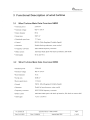
3.1 Wind Turbine Maln Data Ovenriew NM80
. Nominal power
2750 kW
, Nominal voltage
960 V / 670 V
. Rotor diameter
80 m
. Swept area
5027 m2
. Rotational speed max.
17.5 rpm
. Control
PRVS (Pitch Regulated Variabie Speed)
. Generator
Double feed asynchrouous, water cooled
. Frequeney converter
IGBT PWM frequency converter
. Brake system
lndividual blade pitch with back up balleries, disk brake
, !-ub height
60 mand 70 m
3.2 Wind Turbine Main Data Ovenriew NM92
, Nominal power
2750 kW
. Nominal voltage
960 V / 670 V
, Rotor diameter
92 m
. Swept area
6648 m2
. Rolor speed (max)
15.6rpm
. Conlrol
PRVS (Pitcb Regulated Variabie Speed)
o Generator
Doubl fed asynchronous, water cooled
, Frequency converter
1GBT PWM frequency converter
. Brake system
lndividual blade pilch with back up batteries, disk brake on motor sbaft
. Bub height
77,6 mand 80 m
Operation Manual - NM8Q & NM92
I TIC 726'003 GB
Page
,.
Approval sign: MBN
Editor: PKR/MBN
t Dote ~~~O1-2003
I
-_.__.
11 of 59
~cØGMJC()N"
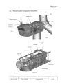
3.3 Wind Turbine Component OveNiew
Blade
Naeelle cover
Obs/ruc/ion lights ~
Hub
Anemometer
Vindvanes &
Cooler
Tower
Generator
Service
Crane
Disk Brake
Gearbox
Main shaft
Contra! panel
Machine frame
Main bearing
Yaw system
f..
TIC 726'003 GB
Date: 24-01-2003
Operation Manual - NM80 & NM92
Editor: PKR/MBN
-I
Approval sign: MBN
Page
12 of 59
~!i'MJCON"
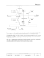
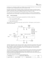
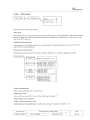
3.4 Contml System
Thc TAC controller is thc central control nnit or the main controller in the wind turbine. lts primary
purpose is to ensure tbat turbine's mecbanical components are not subjected to any excess strain,
wbatever ihc operating conditions. To achieve this, the main controller must monitor wind speed, wind
direction, temperature, pressure, speed of rotation, blades angle, current, voltage, etc. The monitor value
measuremenls are gathered via tbe converter controller, the hub controller and two input/output modules
called TOI#! and TOl#2.
An important parameter is the mcasurement ofthe rotation speed and acceleration oflhe generator. An
inductive dctcctor placed on the t1ange ofthe generator shaft continuously checks this. Knowledge ofthe
rolation speed and acccieration permits the freguency converter 10 adapt the generalor output to the grid
both at cut-in and at cbanges in wind speed during operation. A rpm sensor is also placed on the rotor
shaft t1ange, where the bolt heads are used as an indicator. The lurbine computer constantly monitors the
rotor shaft speed measurement to confirm that tbe generator shaft sensor is transmitting the con.ect signa!.
The main controller is in continual communication with thc hub controller and the converter controller.
The hub controller, which controls the tuming of the blades, is acting as a servo on a pitcb position
reference signa!. The converter controller, controls the generator torque, is acting as a servo on a
generator torgue reference signa!.
The bydraulic pressure levels are also monitored. When the start or stop command is given, the computer
caITies out various routines and testing functions which conlrol the hydraulic systems, for the mechanical
brake and the yawing system.
Tbe main controller keeps tbc turbine in touch with the surroundings. Thc turbine is linked to a wind
park monitoring server, or to the turbine owucr and a service department via a built-in modem. Using the
main controller display and keyboard it is possible to control all the lurbine's functions, Tt is possible to
control the turbine remotely from a pc.
The main controller collects and stores vital data about the wind turbine. This data can be downloaded via
tbe serial communication channels or via modem, and can then be used in analyses. Remote control ofthe
turbine and any such downloading of data require aceess to a special software program. Tbis software is
available on request from NEG Micon.
Turbine control system is distributed all over the turbine. The operalion panel and the main pancl are
placed at the same leveL. The turbine controller contains several components. The most central controller
componenls are des
cri bed in chapter regarding controller panels.
The connection between lhe controller components is dcscribed in thc following l1gure.
-
TIC 726'003 GB
Operatìon Manua! - NM80 & NM92
Page
I
Date: 24-01,2003
I
Approval sign: MBN
Editor: PKRJMBN
_..~-_..
I
13 of 59
~ifGMlCON"
Hub i Nacelle
r--H-ub U:
:1
controller i
-- I Encoder
'_~~I:~mi
conv.
Fiber
L1_ ' ..
Hub
-_._._--_..-
T ower bottom
Naeelle
Tower bottom
EncoderJCu
Fiber,RS422/485
TO#1-J
I' controller
Converter
Fiber
l-::~:l
CAN open
=
Maln controller
ISDN, analog _.....__
DCE3
~
~_o~em
If a sensor measures values outsicle the selected operating parameters, the computer immediately shuls
down lhe turbine. The eause oflhe operational stop is shown as texl on the control system display.
For many of the possible error types an aulomatic start-up procedure is accepted once the operating
parameters are normal again. For other errors a manual restart is necessar, using the control system or
via remote control. In some situations it may be necessary to adjusl or replace parts in the nacelle before
the unit can be restattecl.
Other areas of measurement not described here are located in the turbine control heavy CUlTent section,
where there are motor protection checks and checks on tuses, relays and contacts
NOTE : Read Cbapter 4 in this manual for more specifics on controllcr operation.
Date: 24-01-2003
Approval sign: MBN
Editor: PKR/MBN
._._.~.._...._"~
I
~
Page
Operatìon Mamial- NM80 & NM92
TIC 726'003 GB
F
1
. of 59
~cHGMlC()N'
3.5 Turbine monitoring system
Tbe main controller measure different turbine states variables via the two TO!'s, tbe converter controller,
the hub controller and the main controller il selves. The descriplion ofthe states is grouped by types temperatures, pressures, grid measurements, rotalional speed, etc. The following seclion describes tbe
variables.
3,5,1
Temperature monitoring
these
During operation, the controller monitors a number otturbine temperatures. Max!min values of
tempcratures are stored in the controller. Thc temperature measurements are used for controllng subparts
ofthe turbine like pumps, valves, motors, etc. The temperatures are also used tor troubleshooting, i.e. the
controller stops the turbine if one otlhe important temperatures exceeds or drops below a threshold
values. ¡ftbe alarm is on auto-reset, tbe speeific alarm is aetive until tbe temperature is within the reset
area. lfthe alarm has stop tbe turbine, the turbine automalie siartup, when tbe alarm is reset.
The controller measure the temperature at the following locations:
I. Generator temperature
2. Generator bearing fronl temp.
3. Generator bearing rear temp.
4, Generator slip ring box temp,
5. Generalor inIet temperature
6. Gear oil temperature
7. Gear bearing front temperature
8. Gear bearing rear temperature
9. Gear oil temp. after exchanger
10. Water temp. before eooler
1 L Waler temp. after cooler
12. Ambient lemperature
13. Nacelle temperature
14. Yaw rim temperature
is. Main bearing temperature
16. Operation panel temperature
17. Main panel temperature
18. Contro! panel temperature
19. Converter ambient temperature
20. Stator filter temperature
21. Converter grid side 1 lemp.
22. Converter grid side 2 temp.
23. Converter generator side 1 temp.
24. Converter generator side 2 temp.
25. Tower base temperature
TIC 726'003 GB
Date: 24-01-2003
._--~----~"
Page
Operatìon Manual - NM80 & NM92
15 of 59
Approval sign: MBN
Editor: PKR/MBN
I
----- .~..-
~EGM1CON"
26. Transformer temperature
27. Transformer room temperature
28. Transformer WL temperature
29. Transformer W2 temperature
30. Transformer W3 temperature
3 I. Generator WL temperature
32. Generator W2 temperature
33. Generator W3 temperature
Max!min values are used (by the turbine manufacturer) to establish whether there are any extreme
temperatures that may adversely affect turbine service inlervals.
3.5.2
Pressure monitoring
The controller continually monitors a number of pressures in the turbine. These pressures control the
operation oftbe pumps and are used to monitor the turbine's operating condition. Any pressure reading
outside the pcrmittcel levels wi!l result in the turbine being stopped and an alami message showing what
detected alarm.
The following pressure readings are taken:
1. Pressure gear oil
2, Pressure gear oil filter
3. Pressure shaft brake
4. Pressure yaw brake
3.5.3
Humidity monitoring
of RH is iuipOltant for safety of
The conlroller measure relative humidity (RH) in the turbine. The level
the turbine.
The controller measure the humidity at the following locations:
1. Humidity tower base
2. lIumidity nacelle
3.5.4
Blade monitoring
'fbe hub controller eonstantly monilors the angle of the blades. Tbe blades must always have a positon
determined by lhe main controller (the TAC), which sends a constant flow of information regarding the
desired position to ibe hub controller. The hub controller acls like aservo by following the position
demanded from thc main controller. lfthe blaeles do not turn as required, the turbine will be stopped and
an alarm is triggered. Alarms detected in hub are lransferred to the main controller, which handles fUlther
alami sequencing, including displaying alarm-messages anel eventually alarm call to hotlne. Thc turbine
is also stopped ifthe difference in the position ofthe blades during turning exeeeds parameter-defined
limits. In emergency situations, the hub is able to turn the blade to stop position using balleries.
3.5.5
Rotationai speed monitoring
lneluctive sensors are fitted on the turbine's low and bigh-speed shafts (I-SS, LSS). These sensors give
signals to the main controller, which in turn converts these 10 nnmber of revolutions. The measurement
point for the rotational speed is redundant, two sensor at the HSS and two sensors at tbe LSS. Tbe
TIC 726'003 GB
Date: 24-01-2003
Operation Manual - NM8ü & NM92
Editor: PKR/MBN
.._._----_.._.
Approval sign: MBN
I
Page
16 of 59
~-
~m;:MJCON"
redundant sensor eonfiguration enables more reliable and more accurate measurement. lf one sensor fails
it is possible to carr on operating the turbine untU lhe problem is tixed.
The speed on HSS and LSS is monitored constantly, and ifthe speed is found to be too fast, lhe main
controller wil! stop the turbine. A deeentralized safety module ealled T AC85, measure the speed of HSS
and LSS, and sbul down the turbine by braking the safety line iftbe speed is too high.
The speed signal is an importanI signal for the regulation algorithm. The control oflhe pitch position
demand and the control ofthe generator torque demand are depending on the measured rotational speed.
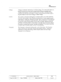
Grid monitoring
3.5.6
The turbine is connected 10 lhe grid trough an autotransforrer with ihree voltage levels.
1. WTG own consumption (400V)
2. Rotor eonnection via eonveiter (640V)
3. Stator connection (960V)
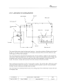
The figure below is a rough sketch ofthe electric part ofthe WTG. The frequeney converter system is
marked with a dotted line.
DoubJy-fed
inctuction
.~,
Stater
generator
Stator eB contactor
¡i
i
I
II
II
I
I
r-------------------I:I
I contactor I
Stotor
'Joltage
: I Converler
geov
I .. Rotor
_ II
Aulo
transformer
I Rotor Frequency converter syslem I
Mein CB
I
640V
1û-20kV
I
I
__ ____~:__ ~~~____ __ ______J
WTG
400V
consumption
50-100kW
!
WTG WfG
consumption consumption
current voltage
The 960V measurements 'Stator eUITent' and 'Stator voltage' and lhe 640V measurements 'Rotor cUITen!'
and 'Rotor vohage' the converter controller uses to calculate the active and reactive power 'P _generator'
and 'Q_generator'. Thc 400V measurements 'WTG consiimption curren!' and 'WTG consumption
vollage' tbe main controller uses to ealciilate the WTG own consumplion active and reactive power
'P_consiimplion' and 'Q_consumption'.
Tbe main controller has three processors, onc ofwhich exclusively monitors and measures grid condilions
on lhe WTG own consul1ption line. To perform this task, the processor uscs an AID converter with six
analog input channels and a digital signal processor for the calculations ofthe various signais. The
converter measures the grid condition at the grid side otthe convertcr and the stator si
de oftbe generator,
to secure tbe converter and the generator.
The grid
- data measnred can be divided into tbc following groups.
Operation Manual - Nfv80 & NM92
TIC 726'003 GB
----~-,-
Date: 24-01-2003
.,
-
Editor: PKR/MBN
Approval sign: MBN
I
Page
17 of 59
~E'G.MjCON"
Voltage
Voltage is measured continuouslyon alIihree phases. The values (RMS phasc to
ground) measured are stored anc! averaged using different averaging times.
Voltage measurements, current and power factor are used to calculate turbine
production and inlemal consumption. Voltage mcasurements are Turther used to
stop the turbine in case of over voltage or under voltage.
Current
The CUITent is measured continuouslyon all three phases. The values measured
are slored and averaged using different averaging times. CUITent measuring and
measuring of voltage are, among othcr things, used to calculate turbine production
and auxiliary consumption. During operation, when the generator is connected to
the grid, the current measurements are also used to monitor wheiher the load is
symmetrie in all three phases. lf asymmetry is too high between the three phascs,
the turbine is stopped and an alarm message is displayed. The current measuring
is further used to monitor failures of one or several phases.
Frequency
The frequency is measured continuouslyon one ofthe pbases, Tbe ti'eiiuency
values measured are stored and averaged using dilferent factors. Frequcncy
measuring is, among oiher things, used to stop tbe turbine in case ofhigh
frequency or low frequcncy.
TIC 726'003 GB
Date: 24-01-2003
Operation Manual - NM80 & NM92
Editor: PKR/MBN .J_.
Approval sign: MBN
Page
18 of 59
~EGM.ICON'
3.6 Power drive ~md contral
The electrical power drive systcm used in NM80-92/2750 is a double fed asynchronous generator and a
frequency converter. The lrequency converter is connected to the generator rotor through slip rings. The
trequency converter can control lhe electromagnetic torque by acling on the electromagnetie tield and lhe
rotor current. As the frequency converter controls the electromagnetic tield in the generator the reactive
power can also be controlled. Regulating the pitch angle oflhe blades and lhe generator torque controls
the speed ofthe turbine. Filters are built in to meet utility requirements regarding barmonic currents and
voltages. Prior to grid connection, ibe generator is energized trough the rolor circuit, to completely
eliminate current surges. In the figure be10w is seen a sketch of a double fed system. The Power range for
the turbine is 0-2750 kW, within avoIlage variation oLlolO%, frequency variation of -510 +3% and
power factor from 0.9 inductive to 1.
~
P Mech
P Stat
s=slip.
Filter
t s*P Stat
s*P Stat t
TIC 726'003 GB
Date: 24-01,2003
Page
OperaUon Manual - NM80 & NM92
Approval sign: MBN
Editor: PKRIMBN
I
.._-_._.
19 of 59
--
~£'G lIi1xx)N"
3.7 Generator
The chosen generator suppliers have more than ¡ 000 generators operating in field. The LP 54 protected
generator bas been designed according to NEGM. specifications. A 6-pole generator running at a nominal
speed of 1 ¡ 00 RPM is used, compared to a4 pole generator tbere wil be !ess stress on the bearings. PT
100 sensors measure lhe temperatures ofthe eleetrically isolated balI bearings. Eleclrical isolaled
bearings, electrical isolated generator suspension and electrical isolated shaft are used to proteet against
damaging circulating currents.
ed. The waler jacket cooling syslem is the primary cooling circuit.
Water jackeI cooled generators are standard for NEGM turbines. The liquid cooling circuil in tbe
generator consists of a liquid inlet gland and a liquid oLitlet gland. The losses from the generator are
transferred to the liquid in two separate ways atthe same time. Directly by heat conduction from stator
lamination to the Iiquid and further from thc internal air-cooling circuit.
The generator is water jacket cool
Tbe slip ring is bought from suppliers with experienee ti.om more ihan 1000 systems. The design lifetime
ofthe slip ring is at least
20 years and the service interval fol" the brushes is 8 month. Wear indicators are
mounted on the brushes, so thcreby service ofthe brusbes can be done, before the brushes are wom out.
3.8 Frequency converter
The four-quadrant operating frequency converter is designcd witb the latestlGBT technology. The
trequency converter controls the electromagnetic torque in the generator and thereby tbe speed in the
turbine. By controlling the electrical torque in the generator, the flcker is reduced considerably. The
converter also conlrols tbe reactive power in the wind turbine. Communication between the lurbine
controller T AC and the frequency converter is done by CAN bus. Tbc frequeney converter generates
harmonics and therefore the stator circuit is equipped with filters, to meet grid requirements regarding
harmonies.
TIC 726'003 GB
Date: 24,01-2003
Operation Manua! - NM80 & NM92
Edilor: PKR/MBN
..._...~-_."....__._,-~.
.,-
20 of 59
Approval sìgn: MBN
I
Page
--
~E'GMlC()N"
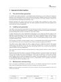
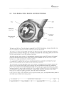
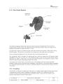
:Ul Huo, Blades, Rotor System and Brake Strategy
Piníon ~ _m . . -"'J --\~ - alade
Access hole
alede turning
Motor /Gear
Hub Flange for
rotor shaft
alade bearing with
inner race
Batterv bank
The hub is cast sa Iron. Tbe bub design is supported by full FEM calculations. Access to the hub is via
one of3 manholes at the rear oftbe bub, witb easy access fromihe naceUe
They blades are ofthe type LM38.8P. The blades are 38.8 m long and made from tibreglass-reinforced
polyester with a continuous tibreglass spar. The blade is mOlinted with a steel flange at the root end. Tbe
root has steel bushings to secure the strenglh ofthe blade.
The blade lurning system consists of 3 independently controUed series-wound DC motors wiib integral
brakes and absolute position encoders, each lurning apinion engaging with tbe inner race of a blade
bearing via a 3-stage speed planetary rediiction gearbox.
A4-quadrant DC amplifier that receives a velocity demand trom a controller in the bub drives each
motor. The hiib controller acts on input trom the turbine main controller.
The rotor system is a Pitch Regulated system - lhe variation is arranged between 0 degrees and plus 90
degrees. Tbis means that the leading edge is pointing into the wind direction during stop. Maximum
power output corrections throiigh blade pitch change will be made when a generator peak power outpul
has been recorded. In order to gain valuable time as to re-adjust the blade pitch and to avoid peak power
(at wind gust) to force high loads to tbe gearbox, variabie speed rotatíon is introc!uced to the NM80.
Please also see chapters regarding generator, electrical system and controller.
In the event of a safety system sbutclown or loss of powerIconIrol system, an independenl battery bank for
each blade tums ibc blade to the stop positíon.
TIC 726'003 GB
Date: 24-01-2003
Page
Operation Manual - NM80 & NM92
Approval sign: MBN
Editor: PKR/MBN
I
-"--"
21 of 59
~E'GNf1CON"
Tbe rotor can aulomatically be put in the Y-position by use ofthe aerodynamic torque from the rotor. A
sensor on the main sbaft wiIl apply tbe brake when the rolor has the right position. Eaeh blade has an
easy-to-fit maintenanee loek thai enables thc blade to be locked in the parked position.
The blade tuming system is the lurbine main brake system. The mechanical brake is only used tor
servicing which requires stationary gear shafts or brake disk.
Emergency stop is pertormed wben safety chain is activated as follows:
i. Disconnection of control voliage for all contactors
2. Disconnection of generator
3. mades turns toward feather position on batteries
4. Turbine idling
Norral stop is performed tor all other stop initiated by the control system as follows:
I. Blades turn wiih controiied speed towards featber position.
2. The generalor follows ihc power speed curve and diseol1nected at I1mi, at zero power.
3. Turbine idling
TIC 726.003 GB
Date: 24,0'1-2003
Operation Manual - NM80 & NM92
Editor: PKRfMBN
1
Approval sign: MBN
Page
22 of 59
~'1G.MlCON'
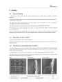
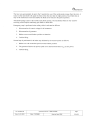
3.10 Malm Bearimg 8. Shaft
Flange
connection for
hub
Main Bearina
nJt;in ('~ht;ff
Main bearing
housíng
Oil pump, tank and
fiter
The main bearing is a double spberical roller bearing ofthe highest quality. Suppliers ofthis bearing are
FAG and SKF. Thc main bearing arrangement is similar as on the other NEG Micon turbiues, and for
wbich good experience is gained.
The bearing is lubricated by an oil bath in the bearing housing and at regular intervals the oil is
automatically changed by means of a separate oil pump with fiter anel tank. Excess oil returns to the oil
tank.
The main shaft is supported by the main shaft bcaring in front and connecled to tbe gearbox input shaft at
the other end.
ow tor e1ectrical power and communicalion lines to go from the nacelle to
the pitch systcm in lhe 1mb. Tbe main bearing housing is bolteel directly onlo the base trame.
The main shaft is hollow to all
TIC 726'003 GB
Date: 24-01-2003
..~.._.._...- ......... ...~_._-_._._...
Operation Manual- NM80 & NM92
Approval sign: MBN
Editor: PKR/MBN
I
_.
2
~:~:9-- J
~ll.GMlC()N"
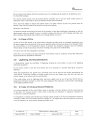
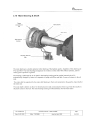
3.11 Gearbox
Gearbox (helical
pfanetary stage)
/
Clip Bushing
for main shaft
High speed shaft & brake
disc
gear suspensions
sliprings
Gearbox (two helica!
parallel axis stages)
Hof/ow shaft
NEG Micon uses eiistom-built gearboxes espeeially designed for the loads in a wind turbine with triplepoint suspension. Safety faetors required by the relevant standards have been considered when proving
that all loads indueed by the rotor are safely transferred.
Gearboxes selected for ihis projeet are based on weIl-proven designs but with adoptions to the special
ready been tested in
requirements of offshore wind turbines. Basie features oflbese gearboxes have al
wind turbines ofthe relevant size onshore. Further, all experienee derived trom reeenl failure analysis,
design improvement and verification testing on smaller wind turbine gearboxes has been addressed in the
design of
these gearboxes.
Thc gearboxes tor NM 80/2750 are of a triple stage hybrid-design, eonsisting of one helical geared
cal geared parallel axis stages. The toal gearbox ratio is seleeted sueh thaI the
planetary stage and two heli
blade tip speed is optimised at the seleeted generator referenee speed. Power control is affeeted by a
combination afblade angle adjustment and speed variation.
TIC 726'003 GB
Date: 24,01-2003
Operation Manual- NM80 & NM92
Editor: PKR/MBN
Approval sign: MBN
Page
24 of 59
~'¡.GMiCON"
The low-speed shaft in the gearbox is implemented as a hollow shaft. Tt encloses the rear end ofthe rotor
sbaft, and the connection is by a strong clip bushing. This special connection between tbe rotor shaft and
gear box, torming a single unit in a tbree-point suspension (rotor main bearing and the two monntings on
either side ofthe gem-box) prevents alignment problems
The gear housing may be cast, welded or a combination, custom-design as 10 NEG Micon's requirements
and specifications. The front end ofthe gear housing forms the torque stay wbere all operation loads and
load reactions are transferred to the maehine base frame The ring gear otthe planet stage is an integral
par of the gear housing. The rear part of the gear housing holding lhe two parallel-axis stages, provides
the linking poinis for a mechanical brake.
The gear housing also serves as an oil tank, holding a suft1cient amounl of oil tor cooling and lubrication
of all gears and bearings. The housing is designed tor free flow ot oil and possible debris towards a deacl
end at tbe lowest point ofthe oil sump. In the inc!ined assembly position, the extemal lubrieation and
cooling system with its fiters is direetly connected to tbe lowest point
TIC 726'003 G8
L..
Date: 24-01-2003
Operation Manual - NM80 & NM92
Editor: PKR/M8N
l
Approval sign: MBN
Page
25 of 59
~cHGMlCaN'
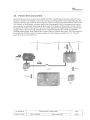
3,12 lubrication 8. Coolirig System
Generator
Heat exchanger
/
\
Termo bypass 450
~"
Water cooler
.
Oil pump and fHter
unit
\
Waterpump
r----- ---,
r-i-I----r
~ il I
I
I
I
i
I
I
/
Test nipple
I!Ii
Ii I .¡ I ..J
I
I
I
I
I
I
I
I
L_____ ___J
I
Test nipple
I
L______\_
Gearbox
Water pump unit
Tbe exlernal lubrication system bas three main functions - it provides circulation, filration and cooling of
the gear oi1. The gear Dil pump circulates tbe oil lbrough a mainstream fiter unit with a thermo by-pass
and tbrougb an oil/water heat exchanger.
The cooler liquid removes heat from the generator and is in turn cooled by a radiator on the nacelle roof,
where airllow behind the blades bas a very effcient action. Apart from the generator and ibe radiator, the
circulation syslem consists of an electric pump, hoses and the beat exchanger, in which the gear oil is
cooled. The syslem is simple and has proved to be both extremely emcieot and reliable.
Water cooling also means that no air !1ow in tbe nacelle is needed. The nacelle cabin is effectively sealed
and protected from altack from cooling air, whicb often contaios humidity, salt, dirt or dust and thereby
corrodes or diities components, joining surfaces and bolts.
The cooler liquid is an antifreeze/water mixture. The cooling pump works continuously except in the case
of emergency stop.
TIC 726'003 G8
Dale: 24-01-2003
Operation Manual- NM80 & NM92
Editor: PKR/MBN
I
Approval sign: MBN
-
Page
26 of 59
~ÐGMlÇOW
:3,3 Disc Brake System
Hydraulic Disc
Brake caliper
Rr:=lt"" ni~k
Mounting holes
forcoupling
Attachment
"/",f",
Mounting bolts for
shrink disk
The brake has integral indicators that inform the control system ifthe linings become wom. Due to
limited number ofbrake actions, the expected life time oftbe brake !inings is long. The linings will be
replaced as prccaution on regular intel'Vals (0' I year).
Thc Disc brake is fitted to an attachment plate. This platc is bolted to the gearbox, which givcs a slrong
and stiff support. Thc brake disc is connected with a shrink disc to the output shaft ofthe gearbox
Tbere are filtings and equipment to loek the brake disk for servicing and other tasks
The mechanical brake is designed for parking and has a back-up system that will keep tbe brake
disengaged in the evcnt of a power cut The mechanical brake is only used for servicing which requires
stationary gear shafts or brake disk. The brake has integral indicators and temperature sensors, which
inform the control system ifthe !inings become wom or bot.
Thc hydraulic unit for tbc brake is an AVN-Bl2 type. The bydrau!ic unit will at normal operation;
maintain a steady pressure to keep the brake disengaged. At grid failure it wil keep the brakcs disengaged
for a limit period and at braking it wil ensure a controlled rcduction ofthe presslle providing a soft cut in
of the brake.
3,14 COl.pling
The generator is linked to ihc outpul sbaft ofihe gear by a coupling, which transmits the driving moment
to the generator without excessive loading on lhe generator bearings. The couplings and shaft are
screened tor safety reasons and protected from accidental contact. A rpm sensor is mounted on the
generator sbaft f1ange to measure rotation speed.
TIC 726'003 GB
Date: 24-01-2003
Page
Operation Manual - NM80 & NM92
Editor: PKR/MBN.J
_._".~"_._.~.,,_.._"'."'_.~... --,.
Approval sígn: MBN
.._-- ------
27 of 59
~£-G Mi:CON"
:3.5 Yaw System
Hydraufic Yaw
Brake calíper
YawMotor
/awgear
Balts for base
frame
Yawgear
pinion
Bali bearing ring with
internal gearing
Tbc yaw system is a derivative ofthe system that is in use on the majority ofthe NEG-Micoo turbines.
The main cbaracteristic is simplicity due to the use of a minimum number of different paiis and dear
separation of functions. Special adoptions make it suitable tor off-shore use,
The yawing syslem is composed ofthe following parts:
.
One 4 point balI bearing with intemal gcar and mecbanical loek.
.
Five planetary gear drives that are driven by squirrel cage induction motors.
.
Six hydraulic activated brake calipers.
.
One brake disc ring at tower top l1ange on which the calipers act.
.
One interface to enable the turbine controller to activate and deaetivate the yaw system.
.
One position-transducer that transfers the nacelle orientation to the controller.
.
One vane on top ofthe nacelle cover that transfers the wind direction to the controller.
.
One manual control box tbat enables manual yawing as is possible tor the panel ofthc controller.
TIC 726'003 G8
Dale: 24-01,2003
OperaUon Manual - NM80 & NM92
Editor: PKR/MBN
I
Approval sign: MBN
. -".~--
Page
28 of 59
~E-GMlL"DN"
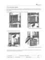
3.16 Controller Panels
The control ofthe wind turbine is split between several panels situated in the tower base, nacelle and rotor
ow, to describe the location
hub. The panels are divided logically in relation to their function and listed bel
in the turbine.
4. platform: Converter panel included converter controller and fiter module:
3. Platform med main operating control panels
2. Platform with Switch gaar (Ieft) og meter box
Tower base. platform with HV/LVMtransrormer
The following tower plan sbows controller panels and medium voltage components. The drawing is not to
scale and must be regarded for information only.
TIC 726'003 GB
Date: 24-01-2003
Operatìon Manual- NM80 & NM92
Editor: PKR/MBN
I
""--_..._..
Approval sign: MBN
.-
Page
29 of 59
_.,
~£'GMlCON"
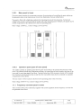
3.16.1
Main panel in tower
The power panel conlains the components necessary for protecting and controlling the parts making up
power cabinet below.
the generator stator circuit (main power circuit). See illustration of
The panel is filted with a ligbtning conductor for protecting the circuit from transients. Cui'rent and
voltage in this circuit is measured and the results sent to the operating paneL. Similarly, all signals used to
control components in this cabinet derive from the operating paneL.
Main voltage: 3x960Vac. ; Control voltage: 230 Vac/24Vdc
Power panel
Operating panel
~
ri~' I
§
~,
~
í¡-:;~~;~:;~~::::-':;!i '~
\_~J
:
fO :1 '
¡~lE''''-..i:.
n
3,16,2 Operation panel (part off main panel)
The cabinet contains an operating panel allowing lhe wind turbine to be operated from the base of the
tower. The cabinel includes lhe components necessary for conirollng the units locatcd at the base oflhe
tower and for receiving signals from them. Transient protection ofthe necessary circuits will be located
here. External communications links to and from the wind turbine must also be connected in a separate
compartmenl oflhis cabinet.
Tbe hour meIers wUI be located on the front oflhc operating panel in the tower base.
Main voltage 3x400+N Vac; Control voltage 230 Vac/24Vdc
1.1.1 Freql.ency converter panel in tower
These contain all the power electronics together with control equipment for the frequency convertel' for
thc generator 1'0101' circuit.
-TIC 726'003 GB
Page
Operation Manual- NM80 & NM92
.....__.
Date: 24,0.1-2003
30 of 59
Approva! sîgn: MBN
Editor: PKRIMBN
-
I
-
(~E'GMlCON'
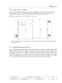
1.1.2 Control panel in nacelle
Thc cabinet includes the components necessary for controlling the units locatcd in the nacelle and for
receiving signals from them. The cabinet eontains an operating panel allowing tbe wind turbine to be
operated from thc nacelle during servicing. See illustration ofnacelle control panel bclow.
iVain voltage 3x400+N Vae; Control voltage 230 Vac/24Vdc
j r::,=:
'm'
.
~,
'"
'"
.1
i_~.- ..
Control panel included the TOl#2 and thc operator panel (OP) for remote control the main controller
in the tower base.
1.1.3 Controller panels in rotor hul:
There are four panels for controlling the pitch system: one main control panel, and three identical blade
panels. Tbe main control panel contains a 3-axis controller, wbich communicates with lhe main turbine
controller (TAC Tl computer) via an RS485 serial link. The 3-axis controller receives pitch position and
rate dcmands from the TAC Tl computer, and generales individual analogue velocity demands for tbe
pitch drives for each bladc. In addition to the 3-axis controller, the main control panel has a battery
charger for cbarging the emergeney stop batteries in each blade panel and power supplies for eacb blade
box. Each blade box houses the pitch drive for that blade and the battery pack for that blade.
~'
TIC 726'003 GB
Date: 24-01-2003
Operation Manual- NM80 & NM92
Approval sign: MBN
Editor: PKR/MBN
I
, ,-
Page
31 of 59
~£GMiCON"
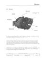
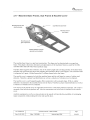
3.17 Machine Base Frame, Sub Frame 8. Naceile Cover
Mountíng area tor main
Cast Machine base frame
bearing hausing
Mounting area for
Yaw system
Mounting area for
gear suspensions
Welded Subframe carrying
generator end auxiliaries
The machine base tìame is a rigid cast conslruction, The shape can be characterized as an open box
frame. Tbis sbape is the direct dcrivative and optimisation oftbe machines frames as used for lhe 600750-900-1000- I 500 kW NEG-Micon product range
The Base frauie supports the sub frame. Oue to the relative bigb sides and the geomctry oflhe base frame
end plate, the sub trame tbat carries the generator and auxiliaries faces a stitT support. Tbe sub tìame itself
is composed of 6 parts; 4 folded beams and 2 stiffener beams bel
ow the frame.
The nacelle cover is supported on botb tbe machine frame and the sub frame by means of rubber-stee!
elements. Theret(Jre a proper load distribution as weil as a reduction of vibration level is obtained,
The nacelle cover is a self supporting glass fibre construction with a smooth shape. With six rubber
elements it is attaehed to tbc machine frame and sub frame. Therefore a proper laad distribution as weil as
a reduction ofvibration level is obtained.
Thc rear top ofthe nacelle cover is supported and tòrmed as a beli-hoist platform (optional). Thc cooler is
mmmled at the helio-hoist platlòrm raiL. Also the anemomeler and wind vane is mounted on the nacel!e
cover.
Auxiliary equipment as wel! as a crane solution in the nacel!e wil! provide tbe possibility of exchanging
major components wiibout taking the rotor and nacel!e down.
TIC 726'003 GB
Date: 24-01-2003
Operation Manual ~ NM80 & NM92
Editor: PKR/MBN
Approval sign: MBN
Page
-J
32 of 59
. ~..~--~..._.- ~_.
~EGMJCON'
3.18 Tower 8. fOl.mdatiol1
The tower is lubular formed by rolled steel plates, All weIds are regularly inspected during manufacturc
by an independent inspection body. The tower is sandblasted and effectively surface-treated for off-sbore
sites. The standard colour is grey-white, corresponding to the colour ofthe nacelle and blades.
The tower top f1ange is constructed as a wide !lange which functions as an internal brake disk for the
yawing brake systcm. The yawing ring is bolted directly to the top flange. 1'0 ensure perfect f1atness arrl
toleranees on lhe integrated top f1ange and yawing brake disk, the lalter is welded separately to the upper
tower shell, wbich is % rn high. Tt is then maehined, and finally the tower top is welded to tbe other tower
sbells, which make up the top section.
Thc individual lower sections are bolted with !lange joints. At each point where the tower is joined, a
platfonn is inserted for inspection and tightening of tower bolts. The top platform gives a convenient
standing height under the yawing system. Frorn here tbere is intemal access to the nacelle,
Access to the tower is through a lockable door at the base. Below the door platform the high voltage
transformer is placed directlyon the foundation concrete. At the door platform the MV - switchgear is
placed as weIl as a turbine control panel lor remote control ofthe turbinc control system in the nacelle.
At tbe first platform the power panel is placcd. And at the second platform the trequency converter is
mounted.
Thc ladder is of aluminium and is in one pieec right from the base of ihc tower to the top platform under
the yawing system. lt is filted with a fall protection system mounted on the centre of the ladder rungs.
The tower wall and the ladderfittings act as a back boop.
The tower can be equipped with a lift. The lift wil endjusl below the tower dampers at the towcr lop.
Thc towcr and nacelle are lit by ligbt litings. There are also power sockcts for tools etc.
A dehumidification device is installcd at tbc base of the tower to control the intemal climate. This
ensures a good internal climate, effectively protecting the tower and boli assemblies trom corrosion,
wbatever the outside conditions.
Two types of offshore foundation are applicablc for this turbine: A mono-pile foundation or a traditional
concrete foundation. On the mono-pile solution an outside access platfonn is wclded to the foundalion
sleel section. On the concrete solution the foundation it selves serves as a platform.
TIC 726'003 GB
Date 24-01-2003
Operation Manual - NM80 & NM92
Editor: PKR/MB~_~_J~~...._._
Approval sign: MBN
Page
33 of 59
_._.-
~E'GMICON'
3.19 lightning pirtection
3.1!U
rotal coiicept for iightiiiiig protectioii of wiiid turbiiie
To assess possible strike points on the NM80-92/2750 wind turbine, the Rollng Spbere method is used.
An imaginary sphere is rolled over the wind turbine. Wberever the sphere touches the wind turbine,
lightning strike is possible. The method takes into consideration the fact that lightning does not always
strike the highest point. The diameter of the imaginary sphere is determined by the desired protection
leveL. Here protection level
1 is applied, the strongest under lEC 61024. At protection level i the radius
of the imaginary sphere is 20 m. All points whicb tbe sphere can touch on the wind turbine are possible
strike points and are called lightning protection zone O. Within lightning protection zone 0, componenls
must be able to wiihstand a direct lightning strike.
Componenls in ligbtning proteetion zone 0 must be able witbstand the ful! ligbining current, set for
offsbore turbines at 200 kA 10/350 e'S.
In the areas in which the imaginary sphere lorms shae!ows there wil! be no direct lightning strikes bul the
components in tbese areas must be able 10 tolerate the fuU eleetro-magnetie field.
This area is ealled zone OE, Zone OE wiI for instanee be the area where meteorologIcal equipment is
mounted.
Tbe naceUe and glass fibre housing are eonstructed as a Faraday cage witb a metal network in/under the
glass fibre housing. The naeelle ean then be considered as being in zone 1. In zone 1, possible lightning
transients are further reduced, Tbc level is 6 kV 1.2/50e,s or 3 kA 8/20 8e,s.
The wind turbine tower is also lighining-protected to level i.
Metal electrical cabinets in lightning protection zone i should be regardecl as lightning protection zone 2
intemally. The level for lightning transients in lightning protection zone 2 is 0.5-2 kV 1.2/50 e's,
depene!ing on signal type.
Components in the indiviclual lightning prolection zones are overvoltage-protected at the levels indieated.
3.19.2 OlielVoitage protectioii of compoiieiits iii lightiiiiig protectioii :wiie2
ElectronIc eomponents and other eleetronic equipment sllpplied by NEG Micon Control Systems bave
been tested to IEC 801-5. Supply cables have been tested to 2 kV common mode and i kV differential
mode.
For communication purposes, optical cables are usee!, so bere lightning arrestcrs are not relevant.
3.19.3 OvelVoitage protectioii of compoiieiits iii iiglitiiiiig protection ;wiie1
In lighting proiection zone I are items sneb as the power panel, frequency eonverter panels. operating
panel and control paneL. Supply intake in tbe power panel is overvoltage-protectee! by lightning arrestcrs
with a nominal e!iseharging eurrent of 15 kA 8/20e,/s and a limil discharging current of 40 kA 8/20etls.
Signal cab
les are protected by sereens. In addition signa
I cables from thc control panel are protectee! by
varistor damps, eapable of dealing wilb disebarging enrrent of2.5 kA 8/50",/5.
Power transformers have lightning arresters on the primary side. VariOlIs control transformers also have
lightning arreslers on tbc primary side.
TIC 726'003 GB
Date: 24,01-2003
Operation Manual- NM80 & NM92
Editor: PKR/MBN
Approval sign: MBN
I - ...._..__.._.._....
Page
34 of 59
~ifGMiC()N'
3.19.4 Overvoitage protection of wind measurement equipment in zone OE
Wind measuremenl equipment is mounted where no direct Iighting strike can reaeh it. Tbis is done by
placing a lightning conductor on the boom on which tbe wind measurement equipmenl is mounted.
Cables tìom the wind measurement equipment are led by pipes 10 tbe control panel, where the individual
conduclors are overvoltage-protected by varistor damps eapable of dealing with a discharge current of
2.5 kA 8/20~s.
3.1!Ui Measurement report and docl.mentation
At handover a report wil! be drawn lip demonstrating/measuring ibe transition impedance trom critical
systems to earh, together with relevant documentation from the subcontractor and operating and
maintenance guidance for periodic checks.
3.19.6
Blade protection
The turbine uses LM glass fibre blades or alike. The blades are lightning-protected with LM's standard
solution wiih two sets of receptors on each side of the blade tip and with conductors ¡eading down
througb lhe blade and connected to the blade tlange. Leakage ofthe lightning current is not practised, i.e.
the lightning CUlTent passes through the blade bearing. A non-corroding liquid damper using glycol is also
instal!ed, and electrical!y connected to thc receptor.
3.19.7
Biade tuming system
Lighting ciirent passing through blade bearings wil! not cause any significant damage, as there is
extremely good e!ectrical contact through the blade bearing because either it is not in motion or it is
moving slowly, 50 there is no lubricant film.
3.19.8 Spinner and transmission system
Tbe gearbox is partial!y insulated, as it is suspended on rubber mountings, NEG Micon uses a discharge
system placed on the locking wheel ahead of the main bearings, thus minimising lightning current
through the main bearing, The di5cbarge system consists of combs/col!ector sboes with replaceable
copper brushes.
3,19,9
Main hearing
Due to the current development stage ofthe tendered wind turbine, the technical solution has not yet been
finalised, in calculations, investigations and testing
lf come out thals necessary tbe main bearing wil! get a brush device to guide the lightning eurrent before
it reaeh the main bearing
3.19.10 Gear
Due to tbc current development stage ofthe tendered wind turbine, thc teclinical solution has not yet been
finalised.
3.19.11 Nacelle
The nacel!e is exeeuted as a Faraday cage. The nacelle boiising is in glass fibre with integral cable
network or a cablc network immediately beneath the housing. Thc cable network is connected to the
metal trame ofthe housing, which in turn is equipoientially bonded with the base tì.ame.
Operation Manual- NM80 & NM92
TIC 726'003 GB
Date: 24'01-2003
Approval sign: MBN
Editor: PKR/MBN
.-
I
_._._-."
Page
35 of 59
~.lì":;.MlCON'
All major components in the nacelle are equipotentially bonded with the base frame.
The weather station on top of the cooler behind the nacelle is f1tted with lightning conductors. The
lightning conductor is equipotentially bonded with tbe base frame.
Lightning current from tbe blades is conducted to the base frame via the discharge system on the main
shaf! with copper brushes or carbon collector shoes. The base frame is part of the Faraday eage, so that
minimumlightning current is conductcd through the main bearing.
3.1!l.2 Yawiiig system
The lighining current is eonducted through the yawing bearing. The yawing bearing is pretension and
moves only very slowly, so for tbese reasons and due to its large dimension, there is good electrical
contact through the yawing bearing.
The yawing bearing is diuiensioned to 300,000 rpm at a much higher rotational speed. The yawing
bearing is expected to undergo approx. 10,000 rotations during the lifespan ofthe wind turbine.
3.1!l.3 Tower
The lightning current is conducted down through the tower. The lower itself is used as conductor. Joints
between tower sections are zine-eoated, giving good metallic contact all the way round.
3.1 !U4 Earthiiig system
The earthing device/system earth is executed as a foundation earth. The volume of the foundation
compared with the specif1c resistance of earth means that the expected transition resistance to neutral
earth ((ir each foundation wil! be less than 2 ohm.
System earth is executed as a TN-S system. The TN-S system has a point in the supply system, the power
transformer's star point, conneeled directly to earth, while exposed parts of tbe wind turbine are also
connected to earth. Throughout the whole installation tbe TN-S systern has separate neutral and earth
conductors.
All protection conductors are as a minimum dimensioued and marked in accordance with the prescribed
nonns in the Directive lor Electrical Installations and Machinery, wbieb also refer to 439-1 low voltage
panels.
3.1!U5 Medium voltage PllIllt
The power transfonner has a lighining arrester on the high-voltage side.
3.19.16 Coiitml system
Reference is made to section "Total concepl for lightning proiection olwind turbine"
A lighlning sIrih detector of a make sueh as Jomitek is also titted. Lightning strikes over 0.5 km are
registered with a time stamp.
In the case oflightning strike in tbc lower cooslruction in which the lightning detector is rnounted, a relay
signal is immediately emitted as an indication of lightning strike. In the case of a direct strike in the
vieinity of the lower constniction, no indication wil be given. Nor will disruption to the 230 V supply
trigger an indication, Tbc lighlning delector registers both weak and very strong strikes. In the case of
error in tbc power supply, the lighlning detector will continue to register ligbtning strikes and save this
information until full power supply is restored and the relay signal can be released, The power supply is
monitored and in case of error a relay signal is emitted.
TIC 726'003 GB
Date: 24-01-2003
Operation Manual- NM80 & NM92
Editor: PKR/MBN ,J
_._..._.._"_._~,,..~~._.. ...._~.._.~~_...._.
Approval sign: MBN
Page
36 of 59
~llG MIX;ON'
Tbe lìghtning detector system fulfils all relevant EU norms and Danish regulations, including tbc Heavy
Current Order, the Low Vollage Directive and EMC. Park communication is done optically and will not
send transients to other turbines.
TIC 726'003 G8
~-
Dote: 24-01-2003
-
Page
Operalion Manual _. NM80 & NM92
37 of 59
Approva! s¡gn: MBN
Editor: PKR/MBN
I
"_.._._..__.-
~EGMlC()N"
4 Operation of controller
To describe tbe controller user interface, ibe description is splil into tbree sections, keyboard, display and
operator paneL.
4.1 Keyboard
The keyboard is designed with pushbuttons to operate in the menu system (numerical buttons, arrow
buttons, enter button), and push bottoms to overall operation command to lhe main controller (start, stop,
reset, yaw buttons). The following iable gives a brief description oftbe keyboard.
Numeric buttons Tbc numeric buttons is used for changing parameIer values in tbe controller, e.g.
date, time, parameIers, etc.
Arrow buttons There are foll arrow keys on thc fronl panel: .-, --, l and Î. These buttons are
used to move througb the menu system. Thcre is an accelerator on these buttons in
long menus, i.e. if an arrow button is held down thc view in the menu will scrol!
faster and tàster up or down through the menu.
Pressing this button (.-) moves the cursor one space to the lelt, or cbange lhe
view to a higher level in the menu system.
Pressing this button (Î) moves tbe cursor one space up in lhe menu system or in
the CUlTent menu.
Pressing this button (--) moves the cursor one space to the right, or moves the
user to a lower leve! in the menu system.
Pressing this button (l) moves the cursor one space down in tbc menu system or
in the current menu.
Enter
Thc Enter button is used tor conlinning thc parameters entered by means ofthe
numeric buttons and for staliing or stopping thc various test functions (see Service
menu).
Yaw buttons
These two buttons are used tor manual yawing. Manual yawing is staiied and
stopped by pressing these two keys.
Reset
Wben this button is activated, a!anns wil! be reset, if conditions for reset is OK.
Staii
Use ihis button to start the wind turbine. lfthe turbine has any activated alanns
while pressing lhe Start buiion, tbe effect is likc pressing the Reset button. lfthe
turbine doesn't have any active alarms, the turbine starts up the lurbine,
Stop
Pressing Stop button stops the turbine using the b!ades. Thc display sbows a
ua! stop message.
man
Prev.
Press this button to relurn 10 the previous menu.
Clear
This button wil! c!car al! data in the line where the cursor is localed. This is done
by pressing the Clear kcy and conlirming with the Enter kcy.
r--
TIC 726'003 GB
Date: 24,01-2003
Page
OperaUon Manual - NM80 & NM92
Editor: PKR/MBN
1
38 of 59
Approval sign: MBN
"._,~.~~~_L,._,.._
~E'G.Mí:CON"
4.2 Display
The display is a text-based version, witb 4x40 ebaraeters. The display is illuminated when pres any ofthe
buttons, and after a period with no menu aclivity the light will aulomatically turn off
The main conlroller has eight LED's, wbieh have the following information:
~
~
-
~J
Receiving data
I
--
,
I
L Sending data
~
~
~i
~
i lI I
_-J
I~ -,
L-~
Generator sensor signal
I
Rotor sensor signa!
I
Wind sensor signa!
I
4.3 Operator panel
At the eontrol panel loeated in the nacelle, an operalor panel is present. The operator panel is a remote
control to the menu in thc maio controller located in tower base. There is no ditTerence in using the
interface at the main controller in tower base and the interface at the control panel in the nacelle.
4.3.1
Paiie! Goiifiguratioii
An operation panel is located in the lurbine naeelle, making it possible to control the turbine from the
naeelle. The operation panel has the same keyboard and display as the main controller. The
communication between the TAC and lhe operation panel is via fiber optic cables.
The Localmenu is activated by switching a random DipSwitch ON.
The panel wil! show the LocaliVenu on tbe Display: (The display wii scrrJiI when !ine 5 is displayed)
TIC 726'003 GB
Date: 24-01-2003
Page
Operation Manual - NM80 & NM92
Editor: PKR/MBN
1
Approval sign: MBN
r
39 of 59
(~ÐI,MlCON'
Line l: Program-number
1999159 - Rev. 01-04-16
Line 2: 10 Number
(Key 0-9)
00000011
Line 3:
Protocol Mode
(Key left/right)
DCEO
Line 4:
Baudrale
(Key left/rigbl)
19200
De/ault OP settings
LiDC 1 shows program-number and I"evision-date. This line is only fol" infonnation.
LiD.
2
shows the operating-panel (OP) 10 number.
When using lhe OCE3-Protocol, make sure that the OP 10 & the TAC 10 are identical. Otherwise the
T AC and the OP wil! not communicate.
The 10 number is typed in using the keys "0 - 9". The "Enter" key saves the selected lO-number.
The ID-number can consist of max. 8 digits.
LiDe 3 shows the selected Protocol-Mode. Select either OCEO or OCE3 protocol using the "RightArrow" or "Left-Arrow" key. "Enter" key saves the selected Protocol-Mode.
LiDe 4 shows the selected Baudrate. Select from 2400 -/ 38400 baud using the "Right-Arrow" or "LeftAn.ow" key. Thc "Enter" key saves the selected BaudRate.
Line:; shows the selected Character sct. The OP receives cl1araeters from the TAC. This funclion can
convert the received character to a special cbaracler, like "æ, ø, å" in Danish.
(ä, Ö, ü in Gennan)
Generally:
"Right-Arrow" switches the eurrent value one step up. (e.g. ti'om 9600 to 19200 in seleeting BaudRate)
lfthe highest value is reacbed, (38400) and the "Right-Arrow" is pressed again, the lowest value wil! be
displayed. (2400)
"Left-Arrow" switches the current value one step down. (c.g from 19200 til 9600 in seleeting BaudRate)
Ifthe lowest value is reached, (2400) and the "Left-Arrow" is pressed again, the lowest value wil be
maintained. (2400)
"Enter" saves the selected values to the OP-Eeprom.
l)scaril Changes: Press "Up-Arrow" or "Down-Arrow". This wilT reslore the original value.
A change is only valid by pressing "Enter",
TIC 726'003 GB
Date: 24,01-2003
Operation Manual - NM80 & NM92
Approval sign: MBN
Editor: PKR/MBN
I
Page
40 of 59
-
~.¡¡GMlCON"
4.4 Operatiori box
The operation box is located in lhe turbine nace!!e, making it possible to manua!!y control the yaw
system. Tt is possible to move the box around the nace!!e. This is used, for examplc, during maintenance
work. The operation box has two switches: an emergency stop and a manual yaw switch for clockwise
and counter-clockwise yawing.
4.4.1
Emergel1C)f switch
The emergency bulton on the operation box is eonnected to thc emergeney line. If this push button is
aetivated the turbine will perform an emergeney stop.
4.42
Yawswitch
The yaw switch has three positions - yaw CCW, yaw CW and neutral spring released position. lfthe yaw
switcb is turned as indieated in the tigure below at left, the turbine wi!! yaw counter-clockwise. When lhe
switch is released, the switch automatica!!y turns to the natural position, Similar action for yawing
clockwise.
I YAW
TIC 726'003 GB
Date: 24-01-2003
Neutra! position
i YAW('W
Operation Manual - NM80 & NM92
Approval sign: MBN
Editor: PKR/MBN
I
- .-
Pa
41 (
._._~
~:9 1
~£-GMlCON"
5 Description of menu system
The main controller menu system contains a status menu, and a number of sub menus. The arrow keys on
the front are used 10 toggle between the menus.
Af
ion
ter power-up, the main controller will display a start-up screen showing the software lype and vers
of software executed on lhe main controller.
The status menu displays the fundamental statcs ofthe turbine. lfthe menu system isn't used for a period,
the menu system automatically returns to the status menu. Pressing the right arrow key accesses the main
menu. The main menu shows the menu stmclure ilustrated below.
Main menu
Status
Grid
Status menu
.. Operation counters
Temperature
Pressure
Us er parameters
Alarm log
Alarm statistics
Service m en u
Configuration
5.1 Status menu
The status menu shows the slatus of the wind turbine:
2002-08-23 11: 36: 11 Generation
Rotor: 16.5 RPM Generator: 1101.2 RPM
2751 kW 15.6 mis PD 5.35° AP 5.33°
Generation
1 sec.
Yaw fault (0)
wind speed (mis)
Pmver (kW)
Nacelle position
-5.3
1 min
-1. 3
15.6
14.9
2751
2750
10 min
0.2
14.2
2750
348 0
25 .
Yaw counter
Line number:
1. Date, time and CUlTent operating status for lhe turbine.
2. Rotor rotational speed, generator rotational speed.
3, CUlTent production, wind speed, pitch demand (PO) and actual pitch (AP).
4. Status line, this line describes tbe status for tbe lurbine. Tbis line shows any alarms
recorded in the turbine. If no alarms/warnings are active the operation mode is displayed.
-
Dale: 24-01-2003
Page
Operation Manual- NM80 & NM92
TIC 726'003 GB
42 of 59
Approval sign: MBN
Editor: PKR/MBN
._---_.~.
I
."._.~ .....-
~'¡'G Mii:O¡;ff
5. Location of I -second data and location of I -minute data and lO-minute data.
6. This line shows the average ofyaw fault tor l-second, I-minute data and lO-minute data.
7. This line shows the average wind speed for l-second, I-minute data and lO-minute data.
8. This line sbows tbe average power production for l-second, I -minute data and lO-minute
data.
9. This line shows the position otthe nacelle relative to tbe geographic north,
10. The last line is tbe degree of cable twist relative 10 the cable twist centcr.
5.2 Griel mem.!
The grid menu contains measured data on the 400V power lines dedieated for turbine own consumption.
At thc bottom otthe menu tbe total power produetion ofthe turbine is printed. The values in this menu
are one-second average values.
Ll
L2
L3
389
790
373
771
385
795
304.2
284.7
Voltage
Current
KW
KVAr
Cos phi
-5.1
3
7.9 kW
-4.7
0.99
0.99
Quad.
303.0
-3.9
0.99
3
3
-13,7 kVAr
50.0 Hz
Line nnmber:
i.
L I, L2, and 13 describe the phase concerned.
2.
Voltage for the three phases.
3.
CUlTent fOf tbc tbree pbases.
4.
lndividual power output for the three phases.
5.
lndividual reactive power output for the three phases.
6.
Power faclor for tbe three phases.
7.
Quadrant position for the three phases.
8.
Total power, reactive power and grids frequeney.
5.3 Operation cm.mters
This menu contains data about the turbine operation - productiou counters, eonsumption counters, and
timers for differenl operations. There are further counters and timers on all motors, major conlactors and
mechanical parts. these are found in the Service menu.
TIC 726'003 GB
Date: 24-01-2003
Operatîon Manual - NM80 & NM92
Editor: PKR/MBN
I
Approva! sign: MBN
--
Page
43 of 59
-----
~BGM1CON"
TotaL
kWh
Subtota
i
kWh
Tatal
G kWh
kWh
Sub G
hours
hours
hours
hours
Acc. reactive effect
kVArh
Absorbed energy
kWh
Power consumption (aux.)
Time
Time
Time
Time
Time
kWh
hours
hours
hours
hours
hours
hours
hours
on
ready
alarm
ok
service
Time Tl
Time T2
Availabili ty
%
hours
Power down T 3
A short explanation ofthe inforrnation inthe menu:
Total
This counter is sbowing the total production for the turbine.
Subtotal
The sub counters have tbe same function as the counter 'Total, but they have lhe
possibility, to be cleared, by the userlturbine owner.
Gen. G
Tbe coimter is sbowing the production delivered by the generator.
SubG
Thc sub counters have the same funclion as the counler 'Gen. G', butthcy bave
the possibility, to be cleared, by the user/turbine owner.
Absorbed energy
Counter for the negative produced energy measured by the tree measurement
points,
Acc. reactive effect Counter tor accumulated reactive effecl that the turbine has used.
Power Counter for used power for turbine own consumption.
consumption (am.)
Time on The time for grid connected to tbe turbine
Time ready The time for sbaft brake released.
Time alarm The time the turbine bas been standing with an alarm
Time ok The time where the turbine has been wiihout any alanns.
Time service The time where tbe turbine has heen in service mode (Service key).
Time TI The Tl counter records the time during which lhe turbine brake is releascd and
the wind speed lies between the minimum and maximum wind speed limits.
Time Tl The Tl counter records the time during which the turbine measures wind speeds
between tbe minimum and maximum wind speed limits.
timer.
Availability The turbine availability is calculated by using the Tl and Tl
Power down T3 Thc T3 is a ¡¡mer for no griel present.
Thc availabitity otthe turbine is calculated for each turbine by the following foltmla:
Thc TI and Tl counters are summation counters counting from the start-up otlhc tllbinc.
TIC 726'003 GB
Date: 24-01-2003
Operaìion Manual - NM80 & NM92
Editor: PKR/MBN
J
Approval sign: MBN
~
Page
~~ of 59
~BGl\;ÚC()N'
5.4 User parameters
Under tbe User parameter menu tbe following items can be found:
Baud
-...-...J....... i--.--i
,Show
alarm (0/1)
___ -l_~ Time with display light (sec)
l-~-~~~ pa~~_~:;~~:----:t----
~;;'~f~
Data bits (7/8)
Parity (0/1/2)
Stop bit (1/2)
Modem contral (0/1)
Handshake (0/1)
I_~ime with di~_~I_~~__~~_~~_~__:~ec) j
---r
(bytes)
---_-_rf~-:f~;~~t;tt1~_~D)---------J
L Set date/time
~byles)
----,
or pulse dial
,
CCITT or BEll
Echo contral
l
i Set communication protocol
---~
L-__
Cam1 to com2
! Cam
---L
l
,_____I
. Set com. parameters Garni
i Set com. parameters com2
1 ta comS
I Comi
Cam 1la
tamenu
com6
f"'~ Com2 to cam1
CamS to cam1
: Com6 to com1
Menu to com1
i Set communication parameters r4 Set com. parameters com5
I Set com. parameters com6
1...........
! Cam2 ta com1
¡ Cam2 to comS
¡ Com2 to com6
: Set com. links carni
.i~. .8.. .e...t....c. .o..m... .links
com2
: Set com. links com5
Set com. links com6
~ Com2 to menu
1'1
,Cam 1 to com2
CornS to com2
Com6 tocam2
Menu ta com2
WfG ld. no.:
WTG telephone no.:
WTG name:
1 Alarm call1
2 Alarm call2
3 Alarm eall 3
4 Alarm call4
5 Alarm call 5
6 Service call1 .
7 Service call 2 :
Start call1
..
1'-----_..
I CornS to cami
! CornS to com2
¡ CamS to cam6
__~ Cam5 ta menu
i
Com1 to cornS
; Com2 to cornS
Com6 tocomS
Menu to com5
Stop cal11
alarm ca1l parameters
Start call 2
Stop call2
Start call 3
Stop call3
i Com6 la cam 1
¡ Com6 to com2
Start ca114,
i ; Com6 to coms
Stop call4
I~ Corn6 to menu
Corni to com6
Start cal! 5,
Stop call 5
Cam number alarm call
Communication silent
Com2 tocom6
: ComS to com6
¡ Menu to com6
Call again
Retry times
for connection
Select cam port
Print event log
Print aiarm jog
Print service log
Print alarm statistics
Print operation counters
Print all
Print menu syslem
Print parameter list
Generator over speed1
TIC 726'003 GB
Date: 24-01-2003
Operation Manual - NM80 & NM92
Editor: PKR/NlBNJ_..
Approval sign: MBN
Page
45 of 59
~Ei:J!CON"
5.4.1
Set m.er parameter
This menu contains parameters for setting tbe display functions.
lfthis is sel to zero there will he no displaying of alarms in the last
line in lhe menus.
alarm (0/1)
Show
ter last key activation.
Time with display light (sec)
Specifies the time the backlight is on af
Time with display sound (sec)
Time length of the key sound, after pressing a key on the 'I AC
controller.
5.4.2
Set date/time
Set dalc (YYYYMMDD)
Sets the year, month and day
Set Time (HHMMSS
Sets tbe time in the 'I AC controller.
5.4.3
Set communication protocol
Tbe TAC Tl controller has tbe possibility to use tbe same protocol on two communIcations ports. This is
only for DCE protocols. DCE x is an abbrevialIon fOf 'DanControl Engineering protocol x'. FDV 2.00 is
an abbreviation for 'Forenede Danske Vindmølleproducenter' (United Danisb Wind Turbine
Manufacturers ).
DCE 1 com port
This line is llcd for selecting tbc communications port fOf the DCE 1 protocol.
DCE 2 com port
This line is used for selecting the eommunications port for the DCE 2 protocol.
DCE 3 com port
This line is used for selecting the communicalIons poit tor tbe DCE 3 protocol.
FDV 2.00 com port
'Ibis line is used for selecting the communicalIons port for the FDV 2,00
prolocol.
Alarm call com port
This line is used for selecting the communications poit tor tbc alarm call. Thc
is port.
tmbinc will send lhe alarm message out on th
Set communication
parameters
Set eommunicalIon parameters com i
Set communication parameters com2
Set communication parameters cornS
Set communication parameters com6
For eaeh ofthe tom communicalIon ports there are the following set ups.
The baud rale at which the computer receivcs and transmits via the seria!
communications port selectcd.
Data bits (7/8) - NU11ber of data bits reauired for lbe serial channel selected.
Options are 7 or 8 biis.
Parity (0/1 /2) - This parameIer is used to select the parity for the serial channel
selected.
The options are as follows:
No parity = O.
TIC 726'003 GB
Date: 24-01-2003
Operat¡on Manual- NM8Q & NM92
Editor: PKR/MBN
1
Approval sign: MBN
Page
46 of 59
.._.-
~BG lJ1.XX)N'
Odd parity ~ 1.
Even parity ~ 2.
Stop bit (1/2) - Used to determine whether 1 or 2 stop bits are to bc used.
Modem control (0/1) - Selting this to ''1', the computer modem is restricted to
sending only if the modem is conneeted to anoiher modem.
This means that the modem must be able to deteet a OCO signa!. Iftbis is not
the case, the modem wil! eease transmitting. (OCO is an acronym for Data
Carr Deleet).
Handshake (0/1) - This parameter lells the computer whether a handshake must
be exchanged. Handshake means that inpul/output control depends on the
input/output status.
Xoff (bytes)- Software control of data flow.
Xon (bytes) - Software control of data t1ow.
Tone or pulse dial - Is used to delermine whether calls are 10 be made using
tones or pulse.
Tbe above parameters also apply to com 2, i.e. communicalions channel
number 2.
lnsofar as communications channcl number 3 is concemed, the following two
changes apply:
ccrn or BELL - The standard ofthe lelecommunicalions network.
Echo control - Used in lurbines tbat communicate through fiber. Type "I" to
ignore the echo.
Set couimunication
links
Tbis menu is used when lhe lurbine is set up in a park where the turbine has to
communicate w itb the park master turbine or a park PC.
Set communication links com 1:
Com i to com2 -Transfer of all data that is received on comlTImications port 1
to communications port 2
Coml to com5 - Transfer of all data that is reeeived on communications port i
to eommunications port 5
Com 1 to com6 - Transfer of all data that is received on eommunications port I
to communications port 6
all data that is received on communications port I
Coml to menu - Transfer of
to the TAC menu
Com2 to com 1 - Transfer of all data ihat is received on communications port 2
to communications port i
Com5 to com i - Transfer of all data ibat is received on eommunieations port 5
to communications port 1
Com6 to eom i - Transfer of all data that is received on eommunieations port 6
to communieations port I
TIC 726'003 GB
Date: 24,01-2003
Operation Manual- NM80 & NM92
Editor: PKR/MBN
I
Approval sign: MBN
.~_.-
Page
47 of 59
--
~:l'G M1CON~
Menu to com 1 - Transfer of all data tbat is received from tbe menu to
communications port 1
Set communieation links eom2 - This menu is identical to thc menu for
communications port I, bLit for communications port 2.
Set communication links com5 - Tbis menu is identieal to the menu for
communications port 1, but for communications port 5.
Set communication links com6 - This menu is identical to the menu for
Communications port i, but for communications port 6.
Set alarm cal!
parameters
WTO ld. no. - This is an 8-digit identifïcation number for the wind turbine.
WTO telephone no.: - The wind turbine telephone number.
WTO name: - The name oftbe turbine.
1-7 Alarm cal! 1-7 - The first -)- seventh number tbe wind turbine cal!s wben
an alarm occurs
Start cal! 1-7 - Start time for wind turbine cal!s 10 tbe tirst number
Stop cal! 1-7 - Stop lime for wind turbine caUs to the tirst number
lt is only possible 10 cbange the sta,i and stop time for "Alarm cal!" numbers.
The alann cal! numbcr is used for customers who do not wish to reeeive calls
e.g. in tbc night.
Tbe service m,mber is used for ealls to those persons or companies responsible
for servicing the wind turbine.
Com number alann cal! - The communications port that is used for sen
ding the
alarm calI.
Communication silerrt - Silent time on the telephone line before an alaim is
permitted.
Call again - Interval between retries to a spccitic rrumber
Retry times - Number of retries to a telephone number in case of failure to
eonneet.
Wait for connection - This checks and wails until the DCD (Data Carrier
Delect) is presenl before the controller is starting to send data.
Print data
Select com port - The communications port selected here is used to send the
dala sclected in lhe below mentioned lines.
Print event log (press Enter) - Using the arrows 10 place the cursor in tbis line
and then pressing tbc enter key, will print lhe entire event log out.
Prirrl alarm log (press Enter) - Using the arrows to place the cursor in this line
and then pressing tbc cnter key, wil print the entire alarm log out.
Print service log (press Enter) - Using the arrows 10 place the cursor in this line
and then pressing the enter key, will print the entire service log out.
TIC 726'003 GB
Date: 24,01-2003
Operation Manual - NM80 & NM92
Editor: PKR/MBN
Approval sign: MBN
I
_._~_."..__.._.-
Page
48 of 59
...-
~E'G1VfJXX)N"
Print alarm statistics (press Enter) - Using the aiTOWS to place the cursor in ihis
line and then pressing the enter key, wil! print lhe alarm statisties.
Prinl operation counters (press Enter) - Using the arrows to place the cursor in
this line and tben pressing the enter key, wil prints the operations counters.
Print all (press Enter)- This makes a print to the selected port witb all the
menus, event log, alarm log, service log, alarm statistics and operations
counters.
Print menu system (press Enter)- This makes a print oftbe menu system.
Print parameter list (press Enter) - This makes a print ofthe parameIer list.
Over speed test
Test generator over speed 1 (press enter)
5.5 Temperature menu
Tbe Temperature menu shows the temperalure at each ofthe measurement poinis used. The temperatures
are as follows:
Generator iemperature (maximum of generator winding temperatures)
Generator bearing front temp.
Generator bearing rear temp.
Generator slip ring box temp.
Generator inlet temperature
Gear oi! temperature
Gear bearing front temperature
Gear bearing rear temperature
Gear oil temp. after exchanger
Water temp. before cooler
Water lemp. afier cooler
Ambient temperature
Nacelle temperature
Yaw rim temperature
Main bearing temperalure
Operation panel temperature
Main panel temperature
Conlrol panellemperature
Converter ambient temperature
Stator fitcr temperature
Converter grid side 1 temp.
Converter grid side 2 temp.
TIC 726'003 GB
Page
Operation Manual- NM80 & NM92
-
Date: 24-01-2003
Approval sign: MBN
Editor: PKR/MBN
I
49 of 59
. ..~--,-
~IH;MlCDN'
Converter generator side I temp.
Converter generator side 2 lemp.
Tower base temperature
Transformer temperature (maximum oftransformer winding temperatures)
Transformcr room temperature
Transtormer W I temperature
Transformer W2 temperature
Transformer W3 temperature
Generator W I temperature
Generator W2 temperature
Generator W3 temperature
Thc last six temperatures are hotspots in the transformer and the generator windings.
5.6 Pressure menu
This menu presents the displaying the various pressures that can be monitored:
Pressure ge
ar ail
bar
Pressure ge
ar ail filter
bar
Pressure shaft brake
bar
-0.,,-....".... ~.."... J-.."l....
"1"'..
5.7 Alarm log
Tbe alarm log is used to show the most recent 100 alanns recorded. The alarms are displayed in the
following way: Log no., date, and time and alarm text.
1 * 2002-01-30 09:06:57.6050
009 Grid spikes Ll
2 2002-01-01 19:06:55.4530
is
An asterisk "*,, before the time indicates tbat ibc alarm is active. The alann "Grid spikes" is active in tb
example.
TIC 726'003 GB
Date: 24,01-2003
..._.-
Page
Operatîon Manual - NM80 & NM92
50 of t:
Editor: PKR/MBN
__J_____...._u~.._.~._ Approval sign: MBN
-
J
~E-G lH1ÇON"
5.8 Alarm statistics
Choosing the 'Alarm statistics' menu, statistics for all alarms are displayed. The number of occurrences
and the most recent date and tbc total ¡¡me recorded for the individual alarm.
it is tÎuthermore possible to see whether the alarm is active. An asterisk in the last !ine indicates an active
alaim. This is shown in the following example:
Alarm
601 Manual stop keyboard
Tatal
o .5 hours 5 Times
Last
2001-01-30 16,06,55.4530
Active : *
5.9 Alarm snapshot
For every alarm tbat occurs, tbe main controller saves a 'snapshot' of a fixed series of values. Al the
moment the alann occurs the following values are logged:
Rotor speed tRPMl
Rotationa! speed ofthe rotor
Generator speed (RPMJ
Rotational speed of thc generator
Winclspeed icn
I-sec averagcd wind speed signal for thc "vind sensor 1 ¡eft
Winclspccd \en: avg. 1 min
I-min avcraged ,vind speed
Windspeed left 3vg. 10 min
10 min averagcd wind speed
Windspeed right
I-sec averaged wind speed signa! for thc wind sensor 2 r¡ght
Winctspecd right avg i min
I-min avcragcd wind speed
Windspeed right avg. 10 min
10 min averaged wind speed
Winddir. left
¡-sec averaged wind direetion!yaw muit signal from the wind sensor I len
Winddir. left avg. 1 min
l-min averaged wind direction
Winddir. !eft avg. i 0 min
i O-min averaged wind direction
Winddir. right
i-sec averaged wind direction!yaw fhu!t signal from thc wind sensor 2 right
Winddir right avg. 1 min
I-min averagcd wind dircetion
Winddir right avg. 10 min
JO-min aveniged wind direct
Cablc twist counter
Cablc twist counter relative to untwist center
Naeelle position
Naeelle position!direction re1ativc to gcogniphic north
Gem oil prcssure
Pressure of gear ail before geur inkt
Gear oil fiter pressiirc
DitTerenee in prcssurc bctore anel after oil fiter
Shaft brake pressiire
Pressure in the shatl brake calibre
Yaw brake pressure
Pressure in the yaw brake calibre
Hiimidity nacclle
Relative humudity in the naccllc
l-umidity tower base
Rclative humidity in the toqer base
-
._----
TIC 726'003 GB
Date: 24-01-2003
ion
---
Operat¡on Manual ~ NM80 & NM92
Editor: PKR/MBN
Approval sign: MBN
I
"_._._--_....
Page
51 of 59
~E'GMrÇ(N'
Transtormer W i temperature
Transfonncr temperature located in the winding L hotspot
Transformcr W2 temperature
Winding 2 hotspot
Transformer W3 temperature
Winding 3 hotspot
Transformer rooin temperature
Temperature measlIrecl in thc transformcr room
T ower base temperature
Temperaturc measured below the main panel
Main panel temperature
Tcmterature measured in the main panel
Operation panel temperature
Temperature measured in the operation panel located in the tower base
Converter amheint temperature
Air temperature rneasurcd at converter panel inlet
Converter temp. grid side i
Temperature measured on the converter cooling fan grid sidc 1
Converter temp grid side 2
Tcmperatiire measured on the converter cooliog fun grid side 2
Converter temp generator side i
,Converter temp. generator skie 2
Temperature measiired on the converter eooling fan generator side 1
Generator W J temperature
Generator temperature located in the winding 1 hotspot
Generator \V2 temperature
Winding 2 hotspot
Generator W3 temperature
Winding 3 hotspot
Generator bearing front temp.
Temperature measured in the generator bearing front nearby the generator
Generator bearing rear temp
Temperature measured in the generator bearing rear
Generator slip ring box temp.
Temperature measured in the slip ring box
-,
TemperatlIre measured in the gear bearing front !ocatcd at the HHS nearby the
rotor
.,-
Temperature measured on the converter eooling fan generator siclc 2
Gear bearing front temp.
Gem bearing rear temperature
Temperature measured in thc gear bearing rear loeated at the HES nearby the
generator
Main bearing temperature
Temperature mcasured in the main bearing
Water temperature before cooler
Water temperatiire measured between thc generator and thc cooler
Water temperature after cooler
Water temperaturc measured between thc cooler and the heat exehanger
Gear oH temperature
ai! temperature in the gear oil sump inside thc gear box
Gear oi! temp. afier exchanger
ai! tempcraturc incasured between the hear exchanger and thc gcm
Generator inlet temperature
Water temperature meaç¡ured bctwecn the heat exchanger and the generator
Yaw rirn temperature
Temperature measured at the yaw rim
Ambient temperaturc
Temperature rneasurcd below thc nacelle
Nacelk tcmperature
TemperatLIc mcasured in the nacelle below thc contral panel
Contral panel tempemture
Temperature measured in the control panel
Generator temperature
Maximum temerature ofthe trec generator winding temperatures
Transtormer tempcrature
Maximum temcratufC ofthe tree trnnsformer winding temperatures
Voltagc Ll
Voltage mcasured at thc phasc Ll on thc WTG own consumption line
Voltage L2
Voltage mcasured at the phase 1.2 on thc WTG own consiimption line
Voltage 1,
Voltage measured at thc phase 1,3 on the WTG own consumption line
Current tI
Ciirrent measured at the phase 1,1 on thc WTG own eonsumptionlinc
_._-
.._""
-
Date: 24-01-2003
Page
OperaUon Manual- NM80 & NM92
TIC 726'003 GB
Approval sign: MBN
Editor: PKR/MBN
~_.~-~.._--~._..-
i
-
52 of 59
"..~...~ ..._....-
~ll'GMíÇOW
Currcnt L2
Current measured at thc phase L2 on thc WTG own consumption linc
Current 1,
Cunent measured at thc phasc L3 on thc WTG own consumption line
Phase shifter measured at thc phase L1 on thc WTG own consumption line
Cos phi Li
Cos phi L2
Phase shifter measured at thc phase L2 on thc WTG own consumption linc
Cos phi L3
Phase shitì:er measurcd at thc phase 1.3 on thc WTG own consumption line
SinphiLl
rha:;e shHter ineasured at thc phase L i on thc WTO own consumption !ine
Sin phi L2
Phase shifter mcasured at thc phase L2 on thc WTG own consumption ¡ine
Sin phi L3
Phase shifter measured at the phusc L3 on thc WTG 0\VT consumption \ine
kWLl
Phase L i active power measurcd on thc WTG own consumption line
kWL2
Phase L2 active power mcasured on thc wro own consumption line
kWL3
kVAr 1,~
Phase L3 active power measured on th,~ WTG own consumption line
,Phase L I reactive power measured on thc WTG own consumption !ine
kVAr 1,2
Phase L2 reactive power measurcd on the WTG own consumption line
kVAr L3
Phasc L3 reactive power measured on the WTU own eonsumption line
Frequency L 1
Thase L I frequency measured on the WTG own consumption line
kWTotal
WTO total active production rneasurcd as a summation of all the voltage levels
kVArTotal
WTG total reactive production measured as a summation of all thc voltage levels
kWIsec
i -sec avcragcd active power production measured on all thevoltage levels
kWlmin
1 -min averaged active power produetion ineasured on all the voltage levels
kW10min
1 O-min averaged active power production measured on all the voltage levels
kVArlsec
I-sec avcragcd rcactivc power production measured on all thc voltage levels
kVAïlmin
I-min averaged rcactivc power production meusured on all the voltage levels
kVArIOmin
lO-min averagcd reaetive power production measiired on all the voltage levels
Turbine mode
Number of actuul WTU inode
Hub command
Niimber of eommand eommunicated to the hub controller
Pitch demand
A yeraged pitch position deinancl
Pitch demand blade 1
Pitch demand for blade I communicated to the hub controller
Pitch deinand blade 2
Pitch demand for blade 2 communicated to the hub controller
Pitch demand blade 3
Pitch deinand tor blade 2 communicated to the hub controller
, ,
Pitch rale/speed demand for blade i communicated to thc hub controller
Speed demand blade 1
-Speed demand blade 2
Pitch mte/speed demand for blade 2 eomiminicated to thc hub controller
Speed dcinand blade 3
Pitch mte/speed demand for bladc 3 cOlUlUiinicatecl to the hub controller
Blade 1 position
Actual piteh position tor bladc 1
Blade 2 position
Actual pitch position for blade 2
B1ade 3 posilion
Actiial pitch position for blade 3
Operating state blade i
8 operating status bit lor blade I
Operating state blade 2
8 operating status bit tor blade 2
I
TIC 726'003 OB
~.
Operation Manual - NM80 & NM92
I
Pa~
._.
Date: 24-01..2003
Approval sign: MBN
Eclitor: PKR/MBN
I
53 Dj
.._.~--~.
I~
~£GMiCON"
Operating state bladc 3
8 operating status bit for blade 3
Operating state blade unit
8 operating status bit fOf hub unit
Signa! state I
8 status bit fOf blade I
S igoal state 2
8 status bit for blade 2
8 status bit fOf blade 3
Signa! state 3
--
Signa! state ext input I
Extension 1 hub controller input
Signa! state ext. output i
Extension I hub control1cr output
COilvcrter torque f%l
Actual generator torque in % of inax torque
Convciter speed
Rotationai generator speed measiircd by thc converter controller
Conveiter grid side voltage
Voltage measurcd on thc frequency converter line
Converter grid sidc current
Currcnt incasured on thc frequency convcrtcr !inc
Converter activc power (tota!)
Activc power measured on the frequcncy converter !ine ancl the generator stator
\ine
Converter reactive power (total)
Reactive power measured on lhe frequcncy converter line anti lhe generator 8tator
¡ine
Converter cycle counter
Converter incremental counter ror thc communication to ihe main controller.
Converter status 1
8 status bits from thc convertcr
Convcrter status 2
8 status bits from the convertcr
Converter error I
8 alarm bits from the convcrter
Converter error 2
8 alalm bits trom the convcrler
Convcrter error 3
8 alami bits trom thc converter
Converter error 4
8 alarm bits from thc convertcr
Converter crror 5
8 alarm bits from the converter
Converter torque demand l%J
Torque demand in % from maiT) controller to the convertcr controller
Converter phi dcinand
phi angle demand in dcgrec from main controller to the converter controller
Converter com. counter (send)
Main controller incremental counter for the communication to thc convcrter
controller.
Converter command
Conveiter command number from ma
--,
TIC 726'003 GB
Date: 24,01-2003
in controller to thc converter controller
Operatîon Manual - NM80 & NM92
Editor: PKR/MBN ~1
. ."-_._.....~..~ -~_.~_....
Approval sign: MBN
Page
54 of 59
._...._....
~lH::.MJr;ONW
5.10 Service menu
Service menu
11! ~---~':~
¡;~I~--~i-t~~::~uenæ mode ¡~~~-;- -l
Master reset
--- ____J I
Service reset
Service start
Test shafl brake
; N pitch cycles demand
~ N pitch cycles completed ,
i I Pitch test sequence parameters
Pitch test sequence mode
Pitch manuel test mode
Test alarm cal! no.:
Menue! TRIP stator CB
I
i Pitch data menu
.----------------------_._-_._-_._.,....,-.-...-_-----------
i Manual CLOSE stator CB
SERViCE log
¡ Menuel startlstop geer oi! p. ¡ow speed
; Menuel startstop geer oil p. high speed
Enable nacelle mode (O/1J
. Menual slaristop generator heat
Pitch demand biade 1
Pitch demand blade 2
Menuel slartstop water pump
Menuel start/stop oH pump main bearing
Menuel startstop grease pump in hub
Mariual starUstop lubr. pump yaw drive
Manual starVstop lubr. pump yaw bearing
I Menuel startstop lubr. pump gen. bearing I
Even! log
U Manual
; Manual
startstop
start/stop
offline fiter
wind pump
sensor
heat i'
: Manuel startstop main panel heat
Manual starlstop operation panel heat
Manual starfistop control panel heat
Manual starlstop stator filer heat
Maniial start/stop main panel fan
Maniial starVstop operation panel fan
Manual startstop control panel fan
Manual starUstop stator filter fan
--'-~MOd::~:__J
Pitch dernnd blade 3
Pitch rate blade 1
Pitch rate blade 2
Pitch rate blade 3
~
Manual starUstop transformer fan
Manual starVstop nacelle fan
Manual start/stop dehumidifier tower
Y;Ii~I~:,;Ii;ilitIiJ
---------
Set safety shutdown (ENTER)
Set pitch to demand (ENTER)
Move off stop limit all blades (ENTER)
Move off stop limit blade 1 (ENTER)
Move off stop limit blade 2 (ENTER)
Move off stop limit blade 3 (ENTER)
Test stop limit blade 1 (ENTER)
Test stop limit blade 2 (ENTER)
Test stop limit blade 3 (ENTER)
Test run limit blade 1 (ENTER)
Test run limit blade 2 (ENTER)
Test run limit blade 3 (ENTER)
Manual starUstop dehumidilier nacelle
Slade 1 limits: Run Stop:
Slade 2 I¡mits: Run Stop:
Slade 3 limits: Run Stop:
Manual reset lightning sensor
Pitch data menu
Test rotor overspeed (press Enter)
Test generator overspeed 1 (press Enter)
Test generator overspeed 2 (press Enter)
Test overspeed guard (press Enter)
Test alarm funclion (alarm nr)
In thc manual test menu, lhe turbine's motors and various functions can be tested.
Master reset:
This will force the main controller to reset all active alarms. The controller will, by pressing master reset,
make the controller reset under any conditions. This function can be useful during installation, ifthe
controller has multiple alaims,
Service reset:
Some alarms need a 'service reset' don by auihorized peoplc. Thc 'keyboard reset' in front ofthe main
controller panel is a non-critical resel procedure.
Service start:
This function makes it possible to slar! ibc turbine when the turbine is in service mode.
Test shaft brake:
This menu make is possible for the service personnel to manually operate the shaft brakc.
The turbine has to be in service mode and witb no aclive alarms that require shaft brake to stop, when this
test is executed.
TIC 726'003 GB
Date: 24-01-2003
_._._...
Operation Manual ~ NM80 & NM92
Approval sign: MBN
Editor: PKR/MBN
I
Page
55 of 59
,.~
~E'GMICON'
Apply shaft brake
Release shaft brake
Hydraulic shaft brake
Relief valve
Af ter pressure reduction
Start test relief valve
(Press Enter)
(press Enter)
145 Bar
o Bar
o Bar
(Press Enter)
Pitch test ,cqucuee mode:
Only ta be used by service persannel wlth thorough knawledge a/the blade turning systeni.
This menu allows the manual operation ofthe blade tuming system. Tbe service key has ta be tumed
before manual control is accessible. In addition, it is only passible to control the blade tuming system
manually if no alarm is active which narmally uses blade tuming system.
Pitch ma,mal test mode:
This menu allows the manual operation ofthe blade tuming syslem.
Test alarm call no:
This tesIs tbe turbines modem and telephone line. When testing, tbc desired alarm call number is selected.
The desired number to call is found in the user menu, under set alam1 call.
Test ,tatar CB:
Tbc stator CB is open/disconnected/tripped in the service mode by press Enter at the line 'Manual TRIP
stator CB'. Thc stator CB is c10sed or connected via lhe line 'Manual CLOSE stator CB'.
For tesl fans, beaters and pumps it is passible to manually start nnd stop the devices. Thc items below
describe the devices:
.
.
.
.
.
Manual start/stop gear oil p. low speed
Manual start/stop gear oil p. high speed
Mamial startstop generator beat
Manual start/stop affine fiter pump
Man
ua! start/stop water pump
.
Manual start/stop ail pump main bearing
.
.
.
.
.
.
Manual start/stop grease pump in bub
.
Manual start/stop operation panel heat
o
Mamial start/stop control panel beat
.
.
.
Manual start/stop lubr. pump yaw drive
Manual siart/stop lubr. pump yaw bearing
Manual starllstop lubr. pump gen. bearing
Manual start/stop wind sensor heal
Manual start/stop main panel heat
Manual start/stop stator filter heat
Manual start/stop main panel fan
Manual stati/stop operation panel fan
TIC 726'003 GB
Dote: 24-01-2003
Operation Manual - NM80 & NM92
Ediior: PKR/MBN
-_.._.__.
Approval sign: MBN
I
Page
56 of 59
~1lG f!iiÇON$
.
.
Manual start/stop stator filter fan
.
Manual star/stop transformer fan
.
.
Manual slartstop naeelle fan
.
Manual start/stop debumiditier naeelle
Manual start/stop control panel fan
Manual start/stop dehumidifier tower
Maimal reset lightning sensor:
It's possible to manually reset the lightening sensor, by press enter at this line.
Over speed test:
The alarms 254 'Rotor over speed', 251 'Generator over speed l' and 253 'Generalor over speed 2' is
tested by using the build in test over speed function in this menu. By pressing enter al one of the lines the
lurbine will eonlinuously increase the rotational speed without synehronize to the grid. When the alarm
set point for the specific alarm is released the turbine will stop. The controller will only record thc
selected over speed alarm. Tbis means tbe other two alarm types will not be triggered even ifthe limits
for such alanl1s are exceeded. Tt is possible to interrupt the test wbile in progress by pressing 'stop'. For
this test the over speed relay TAC85 should be set to a limit that is higher than the upper limit for lhe
tbree alarms tbat can be set in the controller. The actual rotational speed shown on tbc display ShOiild be
watcbed caretì.illy diiring the test.
Test alarm f",iction:
This test tunction make is possible to test the stop fiinction for a speeifie alarm. Type
in the alarm number.
5.10.1
Min/mal( register
A range of maximum and minimum values, which the computer has delected are shown in this memi.
Each new minimum or maximum value is given a time slamp to show when tbe registration took place.
All valucs in tbe menu can be reset to zero using the 'lnstall parameter' menu. lndividual values ean be
reset to zero by pressing 'CIcar' for tbe element required.
5.10.2
Input/Output
In this menu the actual state oflhe 1'01 inputs and outputs is shown.
5.10.3 Operation counters
All main controller outputs have time and activation counlers. This means ihat the by-pass conlaelor has
two lines. 'Times Sy-pass contactor ON' registers ihc number of aelÍvations oflhe output and 'Time Bypass eontaetor ON' the time the output has been aetivated. This is present for alilines in the menu. The
time is in a I/i 0 of an hour.
5.10.4 Wind sensors
Tbe wind sensor output (wind speed, wind direction) is displayed in this menu.
5.10.5 Softare versions
In th
is menu the eontroller's present software version and revisions ean be secn.
TIC 726'003 GB
Date: 24-01-2003
Operation Manual - NM80 & NM92
Editor PKR/~~~___,_J_,
Approval sign: MBN
Pa£
57 of
,.
~
,~
\l N:ITr; MJ;CON"
5.10.6
WTG setup
WfGtwe 99
wrGsetup
Service menu
NOf~nel pu generator 2750
Nomnel current generator 165
In ihis menu lhe WTO setup is done:
WTGtype:
The turhine type is selecled, When this is done the turbine makes a self-configuration. Tbis means that tbe
turbine is setting the control and regulation parameters, depending on turbine type. Turbine types can be
seen in the WTO lype list.
Nominal power generator:
This parameter is setting the nominal size ofthe generator. Selecting the type in the menu line "WTO
types" wil! set up this parameter.
Nominal ciirrent generator:
Depending on generator type the current can differ, therefore it is possiblc 10 change the CUITent.
Service menu
able test safetytemergency line 1
01 INPUT Transient - stator circuit ON 0
02 INPUT Transienl- stator circuit 0
03 Input generator G feedback on 0
04 Input generator G feedback oH 0
Enabie
temperature
channels
Enable pressure
channels
-nabie temp. generator G
"nabie lemp. gear ail
1
:iable temp. ambient
1
"nabie temp. pitch oil
1
able shaft brake pressure
ablehub ¡niet pressure
nable yew brake pressure
:nabie gear oil pressure
nable power consumption
I
1
1
1
I
1
Enalile aiitomatic test
Select which automatic tests to be performed.
Disalile log events
Select wbieh log events NOT to be written in the log by typing "1".
Enable temperat"re ehaiinels
Enable I disable temperature input
Enable press"re cliaiinelsEnable I disable pressure input by iyping the number I or O.
TIC 726'003 GB
Date: 24-01-2003
Operation Manual - NM80 & NM92
Approval sign: MBN
Editor: PKR/MBN
I
._-_..._.._-~-
Page
58 of 59
~ifGM1CON"
Appendix
Main specification NM80
Main specification NM92
TIC 726'003 GB
Date: 24-01-2003
Operation Mamial - NM80 & NM92
Editor: PKR/MBN
Approval sign: MBN
I
Page
59 of 59