1
User
Manual
I08D708048AD-V2
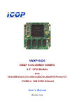
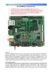
Bus type TFT drive module
7”TFTLCD AT070TN83 V.1
H
A
N
JI
N
D
TFTLCD Type : AT070TN83 V.1
A
T
A
User Manual
MI08D708048AD-V2
BUS Type TFT LCD Module
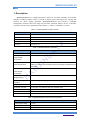
1. Description
MI08D708048AD-V2 is a high performance 16-bit true color TFT controller, the controller
integrates 16Mbytes display cache, to provide 8 display pages and support for copying data
between the various paging operations. MI08D708048AD-V2 also provides a backlight
management, automatic anti-color, image flip and other advanced features, the use of flexible,
convenient, and its various parameters such as Table 1.1 , Table 1.2 and Table 1.3 below.。
Table 1.1 MI08D708048AD-V2 basic features
Description
Interface Type
Intel8080-8
Color format
RGB565
Memory Pages
8 block
Memory Capacity
16MBytes
TFT Panel
AT070TN83 V.1
A
Features
T
Table 1.2 MI08D708048AD-V2 features
Description
A
Features
Write to the specified coordinates of the specified data
X coordinates
Write a data point each, the current X coordinate will automatically add a
N
D
Write data point
automatically
accumulate
Accumulate to the user when the X coordinate of the end of the
automatically return
default X coordinate, the automatic return to the starting Xcoordinate of the
JI
X coordinate
N
user default
X coordinate of automatic return, Y coordinates automatically add a
automatically
accumulate
A
Y coordinates
H
Change the currently
The data displayed on the screen in the memory of any changeon page 8
displayed page
Page switching current
To 8 as the target of any page in memory, write data
operation
Page Copy
In between any two arbitrary regions of memory data copy operations
Automatic anti-color
For any page, any automatic anti-color operation area
Backlight Control
Adjustable backlight PWM signal 64
Flip mirror
On the TFT display on the horizontal or vertical mirror image flip
State ID
Read through the bus interface controller status bits
Table 1.3 MI08D708048AD-V2 Electrical Characteristics
Features
Power supply voltage
Power
1
IO Level
Description
5 ± 0.5V
170mA ~ 730mA
2
User Manual
3.3V LVTTL
www.smartkit.co.kr 1
MI08D708048AD-V2
BUS Type TFT LCD Module
Note 1: 170mA corresponds to the power consumption of the backlight turned off, 730mA corresponds to the
brightest backlight power consumption when this data is the supply voltage is 5V, measured, and the practical
application of power supply voltage fluctuation due to the slightly change.
Note 2: Generally, if the output driver with 3.3V, 5V, IO IO can be directly driven, if the output driver
with 5V,3.3V IO of IO, the IO recommended that you set the 5V weak pull model This avoids the compatibility
level is not too much current caused by IO.
1.1
Operating Instructions
MI08D708048AD-V2 External 20-pin, on a detailed description of each pin, see Table 2.1 .
Table 2.1 MI08D708048AD-V2 Pin Description
Name
Help
1
+5 V
5V power input
2
+5 V
5V power input
3
D0
Data bus
4
CE
Chip-select signal Low active
5
D1
Data bus
6
RES
Active-low reset signal
7
D2
Data bus
8
A0
Address signal
9
D3
Data bus
10
WE
Active low write enable signal
11
D4
Data bus
12
RE
Active low read enable signal
13
D5
Data bus
14
A1
Reserved for future expansion addresses
15
D6
16
A2
T
A
N
D
JI
N
A
H
17
A
No.
Data bus
Reserved for future expansion addresses
D7
Data bus
18
A3
Reserved for future expansion addresses
19
GND
GND
20
GND
GND
1.2
Interface Timing
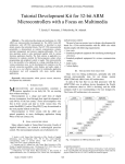
MI08D708048AD-V2 uses 8-bit 8080 bus interface, the specific interface timing, such as Figure
2.1, ,Figure 2.2 shows
Figure 2.1 The timing for the bus to write, when the address line A0 is 0, said address register is written,
the register of MI08D708048AD-V2 for the various registers in addressing the range of0 to 7. When the
address lines A0 to 1 that the value written to the register, on the role of each register, see 2.3.
User Manual
www.smartkit.co.kr 2
MI08D708048AD-V2
BUS Type TFT LCD Module
Figure 2.1 Bus Timing Write
N
D
A
T
A
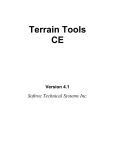
Figure 2.2 The timing for the bus read, read in MI08D708048AD-V2 register in only one, so
in order to facilitate the operation, any read operation will be automatically point to the register,
during the address register A0, and the state of the signal will be ignored。
Figure 2.2 Bus Timing Read
Register Description
JI
1.3
H
A
N
MI08D708048AD-V2 register addresses and functions of each profile, such as table 2.2 shows,
including seven 16-bit registers and an 8-bit registers, for the 16-bit register write operation
requires two to complete a register set, during write operation must be re-written to write low-high
eight eight, and the write operation must be in pairs, for 8-bit register, with a single write operation
to complete the set
User Manual
www.smartkit.co.kr 3
MI08D708048AD-V2
BUS Type TFT LCD Module
Table 2.2 Features register address and
Operation
Width
Address
Name
Features
Reset
value
Write only
16
0x00
CUR_Y
Set the Y coordinate of the screen
0x0000
16
0x01
CUR_X
Set the X coordinate of the screen
0x0000
16
0x02
PIXELS
Write pixel data
0x0000
16
0x03
END_X
Setting automatically returns the
0x031f
coordinates of the X direction, and the
page copy when the end X coordinate
direction
16
0x04
END_Y
Set the direction of the end of page
0x01df
copy Y coordinates when
16
0x05
PREF
Set the current display page, the current
0x0000
A
operation page, backlight, etc.
0x06
RVS_MASK
Anti-color mask set
0x0000
8
0x07
MIRROR
Mirror flip and page copy of the start
0x01
control
8
-
STATE
0x00
N
D
1.3.1 CUR_Y(0x00)
、CUR_X(0x01)
Status Register
A
Read-only
T
16
H
A
N
JI
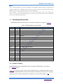
Register CUR_Y and CUR_X used to set the coordinates of pixels to be operating, TFT screen
coordinates of the arrangement such as Figure 2.3 shows, when CUR_Y and CUR_X value
determined, pixels A location is only determined by the subsequent pixel data is written accurately
placed in the A point
Figure 2.3 Coordinate order
1.3.2 PIXELS(0x02)
PIXELS corresponding to register 16-bit color data, if the current page displayed the same
page with the current operation, then the data will be written PIXELS immediately apparent
and CUR_Yselected by CUR_X current active point, if the currently displayed page and the
current operation not the same page, then writes the data will not be
immediately PIXELS presented.MI08D708048AD-V2 color format RGB565, specific
Correspondence between the color spaces such as the Table 2.3 below.
User Manual
www.smartkit.co.kr 4
MI08D708048AD-V2
BUS Type TFT LCD Module
Table 2.3 The correspondence between color code
b15
b14
b13
b12
b11
b10
b9
b8
b7
b6
b5
b4
b3
b2
b1
b0
R4
R3
R2
R1
R0
G5
G4
G3
G2
G1
G0
B4
B3
B2
B1
B0
1.3.3 END_X(0x03)
JI
N
D
A
T
A
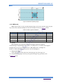
In order to improve the efficiency of pixel data to write continuously, when the
set CUR_X andCUR_Y, each write a pixel, the X coordinate of the current active point will
automatically add one, when the activation point is equal to END_X X coordinate, it will
automatically returnCUR_X also automatically add a Y coordinate. As Figure 2.4 shows, the
assumption CUR_X, CUR_Y, END_X were 400, 200, 500, A point, B point, C point, D point
coordinates are (400, 200), (500, 200), (400, 201), (500, 201). Set CUR_X, CUR_Y, the first pixel
written to the A point, the first pixel writes B100 points, the first pixel writes C 101 points, the
first pixel writes D 200 points, and so on.
N
Figure 2.4 X automatically returns indicate
H
A
With END_X register, you can simplify the process of writing bulk data MCU, MCU needs
to assume(100, 200) for the starting point is to write a 10 × 20 rectangle, then only need
to CUR_X set to 100,CUR_Y set to 200, END_X set to 210, then 200 pixels can write, do not
need to coordinate during the set operation, all coordinates will be automatically calculated.。
1.3.4 END_Y(0x04)
END_Y registers need to tie CUR_X, CUR_Y and END_X use of color in the page copy and
anti-operation, the four registers used to define the operating range, as Figure 2.5 shows, A point
of
coordinates (CUR_X, CUR_Y), B point
coordinates (END_X, CUR_Y), C point
coordinates (CUR_X,END_Y), D point coordinates (END_X, END_Y), page copy and the role of
anti-color operating range is from the A, B, C, D defined by four points .
User Manual
www.smartkit.co.kr 5
MI08D708048AD-V2
BUS Type TFT LCD Module
Figure 2.5 define the operating range
1.3.5 PREF(0x05)
A
PREF register used to set the currently displayed page, the current operation page, the page
copy of the source and TFT backlight, the specific meaning of each bit as Table 2.4 below。
Table 2.4 PREF register bit definitions
Name
Features
b5 ~ b0
BK_PWM
Backlight Control
b8 ~ b6
COPY_SRC
When a copy of the source page
0
b11 ~ b9
CUR_PAGE
The currently displayed page
0
b14 ~ b12
OPT_PAGE
The current operation of the page
0
b15
Reservations
-
0
Reset value
0
JI
1. Control
N
D
A
T
Bit
A
N
BK_PWM duty cycle signal for setting the backlight to adjust the brightness
of TFT backlight, rang Backlight e from 0 to 63, 0 backlight off, 63 on behalf of the brightest
backlight. After power-on reset default value is 0 BK_PWM, that is, backlight off,
the MCU on BK_PWM assigned to non-zero value, the backlight on
H
2. Copy source page
COPY_SRC used to set the data source when the page copy, The range of 0
to 7, corresponding to 8pages in memory, the signal on the page copy operations, such
as Figure 2.6 below
User Manual
www.smartkit.co.kr 6
MI08D708048AD-V2
N
D
A
T
A
BUS Type TFT LCD Module
Figure 2.6 copy of the operatingsignal
H
A
N
JI
Figure 2.6 in the hands of two pages, the above page for the OPT_PAGE, that are currently
working on the page, the following is COPY_SRC, that stores the data source of the page copy
operations, when the copy operation was launched after page, from the master
logic COPY_SRC specified page will be A, B, C, D four-point range as defined by the points one
by one read out, and RVS_MASKXOR, and then write OPT_PAGE the corresponding
position. If RVS_MASK is 0, then this operation simply move the data, if RVS_MASK the value
is not 0, then the process of moving data pixel color values for the mask
will RVS_MASK anti-color, if OPT_PAGE and COPY_SRC point to the same page,
while RVS_MASK is not 0, then the data movement operation has evolved into a pure anti-color
operation. Copy operations on the page for further instructions, see 2.3.6
3. The current display / operation page
CUR_PAGE specified by the currently displayed page, said that the actual display on the screen of
memory paging, the current operation by the OPT_PAGE specified page, a write data operation,
anti-color copying operation, and the corresponding page of memory paging. If CUR_PAGE and
OPT_PAGE point to the same memory page, then write data, inversion, such as operating results will be
presented on the screen immediately, if CUR_PAGE and OPT_PAGE point to different memory paging,
then the operation will not be any OPT_PAGE affect the display on the screen, only to switch to
OPT_PAGE after CUR_PAGE, OPT_PAGE the data will be displayed。
User Manual
www.smartkit.co.kr 7
MI08D708048AD-V2
BUS Type TFT LCD Module
1.3.6 RVS_MASK(6)
RVS_MASK 16-bit counter used to set the color mask, the mask is the role of anti-color logo
in the operation against the need for reversal color color bit, RVS_MASK bit defined
as Table 2.5below。
Table 2.5 RVS_MASK bit definitions
b15
b14
b13
b12
b11
b10
b9
b8
b7
b6
b5
b4
b3
b2
b1
b0
R4
R3
R2
R1
R0
G5
G4
G3
G2
G1
G0
B4
B3
B2
B1
B0
A
T
A
Anti-color operation of the RVS in the MIRROR bit start register (see 2.3.7 ). If the anti-color
operation is required, then the first point to make OPT_PGAE and COPY_SRC also need
anti-color pages, and then set CUR_X, CUR_Y, END_X and END_Y, define the color of the
region need to counter anti-color mask to RVS_MASK write, and then RVS in
the MIRROR-bit register can be written to 1. Anti-colored mask can specify a specific value, for
example, 0xf800 can be used to counter all the red bits color, 0x07e0 green spaces can be used for
all anti-color, 0x001f can be used to counter all the blue bit color, and so and so on.
A
1.3.7 MIRROR(7)
N
JI
N
D
If the page copy operation is needed, then let OPT_PAGE and COPY_SRC point to a
different page, and then set the CUR_X, CUR_Y, END_X and END_Y define the area to be
copied to the RVS_MASKwrite 0x0000 (can also be a non-zero value), then to
the MIRROR RVS-bit register can be written to1. Copy operation is complete, COPY_SRC page
data corresponding to the region will be copied to theOPT_PAGE the corresponding area. Note
that, you can also write to the RVS_MASK non-zero value, the difference is that the data copied
to OPT_PAGE COPY_SRC page is not raw data corresponding to the region, but rather as a mask
after RVS_MASK inverted data
H
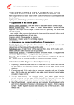
MIRROR register is used to achieve horizontal and vertical mirror image flip, and control
and anti-color page copy operation starts, the specific meaning of the register you
as Table 2.6below.。
Table 2.6 MIRROR register bit definitions
Bit
Name
Features
Reset value
b7 ~ b3
Reservations
-
0
b2
RVS
Anti-color copying operation, and start position on page
0
b1
UD
Control vertical image flip
0
b0
LR
Flip mirror control level
1
RVS-bit counter is used to start page for color copies and operation, prior to
the RVS-bit write 1to the first set CUR_X, CUR_Y, PREF and other registers set the page to be
operating until the regional operations and anti-color mask and other parameters . Anti-color pages
at startup or after the copy operation, RVS bit is automatically cleared.
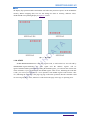
UD bit is used to control the display of the vertical flip, LR bit is used to control the level of
User Manual
www.smartkit.co.kr 8
MI08D708048AD-V2
BUS Type TFT LCD Module
N
D
A
T
A
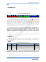
the display flip operation UD bit and LR bits will affect the position of pixels on the TFTand the
memory address mapping data, but not will change the data in memory, different values
ofUD and LR corresponding display as Figure 2.7 below
图 2.1
JI
1.3.8 STATE
显示效果
H
A
N
STATE MI08D708048AD-V2 is the only register read, so read on the bus were all read by
defaultSTATE register A0 during the read signal and the address register will be
ignored. STATE width register 8bit, by reading the STATE register, you can learn the current state
of the controller, if you read back from the STATE register value of zero, indicating the controller
is idle, you can receive and process a new operation, from STATE register read back the value
of 1, indicating the controller is the page copying or anti-color operation, then the controller could
not receiving any MCU write, otherwise it will lead to anti-page color copy or operating error.
User Manual
www.smartkit.co.kr 9
MI08D708048AD-V2
BUS Type TFT LCD Module
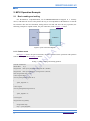
2. MCU Operation Example
2.1
Basic reading and writing
T
A
For the 8080 bus compatible MCU, can be MI08D708048AD-V2 mapped to a memory
device, read and write access to the pointer the way, is not compatible for the 8080 bus or external
bus interface does not have the MCU, analog IO bus can read and write the way operation, the
following example to explain in 8051, the port connection, such as Figure 3.1 below
Figure 3.1 port connection diagram
A
2.1.1 Pointer mode
N
D
For Figure 3.1 shows the port connections, the basic read and write operations with pointers
such as the sample code in Listing 3.1 below。
JI
Listing 3.1 Basic reading and writing pointers
#include "AT89X52.h"
P3_5
N
#define RES
xdata *pTFT_RegAddr = (unsigned char *)0x0000;
unsigned char
xdata *pTFT_RegData = (unsigned char *)0x0100;
A
unsigned char
static unsigned char udlr = 0x01;
H
// Write register address
void TFT_WRegAddr(unsigned char a)
{
*pTFT_RegAddr = a;
}
// Write register
void TFT_WRegData(unsigned char d)
{
*pTFT_RegData = d;
}
// Read register
unsigned char TFT_RData()
{
unsigned char temp;
temp = *pTFT_RegData;
User Manual
10
www.smartkit.co.kr
MI08D708048AD-V2
BUS Type TFT LCD Module
return temp;
}
2.1.2 I/O Bus
For Figure 3.1 shows the port connections, using I/O bus for read and write basic code
as 3.2 shows
3.2 I/O Bus
#define CE
P2_1
#define A0
P2_0
#define D
P0
#define WE
P3_6
#define RD
P3_7
#define RES
P3_5
A
#include "AT89X52.h"
void TFT_WRegAddr(unsigned char a)
T
{
CE = 0;
A
A0 = 0;
D = a;
N
D
WE = 0;
WE = 1;
CE = 1;
JI
}
void TFT_WRegData(unsigned char d)
{
N
CE = 0;
D = d;
H
WE = 0;
A
A0 = 1;
WE = 1;
CE = 1;
}
unsigned char TFT_RData()
{
unsigned char temp;
D = 0xff;
CE = 0;
RD = 0;
temp = D;
RD = 1;
CE = 1;
return temp;
}
User Manual
11
www.smartkit.co.kr
MI08D708048AD-V2
BUS Type TFT LCD Module
2.2
Advanced Operation
2.2.1 Setting display parameters
MI08D708048AD-V2 can be easily and backlight on the display buffer management, specific
examples, such as Listing 3.3 show
Listing 3.3 Setting the display parameters
/*******************************************************************************
* Function Name: TFT_SetPref
* Description: Sets the currently displayed page, the current operation page,
the page copy of the source and backlight
* Parameters:
- Cur_page: the currently displayed page
- Opt_page: the current operation page
- Copy_src: page copy of the source
A
- Bk_pwm: Backlight
* Return Value: None
unsigned char cur_page,unsigned char opt_page,
A
void TFT_SetPref(
T
*******************************************************************************/
unsigned char copy_src,unsigned char bk_pwm
N
D
{
)
int temp;
temp = bk_pwm | (copy_src<<6) | (opt_page <<12) | (cur_page<<9);
// Address register points PREF
TFT_WRegData(temp>>8);
// write data PREF
TFT_WRegData(temp);
A
2.2.2 Filled rectangle
N
}
JI
TFT_WRegAddr(5);
H
Making clear the screen, the picture shows and other operations, will use the rectangle
filloperations, MI08D708048AD-V2 filled rectangular field operation is optimized, when
filling MCU only need to set a good starting point coordinates and end coordinates can be, the
process of filling the coordinates of all points will be automatically calculated, the maximum
efficiency to ensure that filled rectangle, filled rectangle as an example of Listing 3.4 shows
Listing 3.4 filled rectangle
/*******************************************************************************
Function Name: TFT_RectFill
* Description: TFT color fill with the specified rectangle on the specified
* Parameters:
- Start_x: X coordinate of the starting rectangle
- Start_y: Y coordinate of the starting rectangle
- End_x: X coordinate of the end of the rectangular domain
- End_y: Y coordinate of the end of the rectangular domain
User Manual
12
www.smartkit.co.kr
MI08D708048AD-V2
BUS Type TFT LCD Module
--- Color: color to be filled
* Return Value: None
*******************************************************************************/
void TFT_RectFill(int start_x,int start_y,int end_x,int end_y,int color)
{
int i, j, w, h;
TFT_WRegAddr (0);
/ / Address register points CUR_Y
TFT_WRegData (start_y>> 8);
/ / set the starting Y coordinate
TFT_WRegData (start_y);
TFT_WRegAddr (1);
/ / Address register points CUR_X
TFT_WRegData (start_x>> 8);
/ / Set the starting X coordinate
TFT_WRegData (start_x);
TFT_WRegAddr (3);
/ / address of register to END_X
TFT_WRegData (end_x>> 8);
/ / set END_X
/ / Address register points PIXELS
h = end_y-start_y +1;
/ / calculate height of rectangle
w = end_x-start_x +1;
/ / calculate the width of rectangle
T
TFT_WRegAddr (2);
A
TFT_WRegData (end_x);
A
for(i=0;i<h;i++)
for(j=0;j<w;j++)
{
N
D
{
// / Loop fill data
TFT_WRegData(color>>8);
JI
TFT_WRegData(color);
}
N
}
}
A
2.2.3 Page copy operations
H
MI08D708048AD-V2 offers an 8-page display buffer can be specified in any area between
the pages to copy data, the data copy operations in hardware, the copy process
without MCU intervention.For low-speed MCU, when the refresh when a large area, the
phenomenon appears Curtain, flexible use of page copy operations can effectively avoid this
phenomenon, so that the screen displays more fluid, the sample page copy operations, such
as Listing 3.5 show
Listing 3.5 copy operations
/*******************************************************************************
* Function Name: TFT_PageCopy
* Description: copy data between the page
* Parameters:
- Start_x: to be copies of X coordinate of the starting area
- Start_y: to be copies of the starting Y coordinate of the region
- End_x: to be copies of X coordinate of the end zone
- End_y: to be copies of Y coordinate of the end zone
User Manual
13
www.smartkit.co.kr
MI08D708048AD-V2
BUS Type TFT LCD Module
--- Rvs_mask: Anti-colored mask
* Return Value: None
*******************************************************************************/
void TFT_PageCopy(int start_x,int start_y,int end_x,int end_y,int rvs_mask)
{
unsigned char temp;
TFT_WRegAddr (0);
/ / Address register points CUR_Y
TFT_WRegData (start_y>> 8);
/ / set the starting Y coordinate
TFT_ WRegData (start_y);
TFT_WRegAddr (1);
/ / Address register points CUR_X
TFT_WRegData (start_x>> 8);
/ / Set the starting X coordinate
TFT_WRegData (start_x);
TFT_WRegAddr (3);
/ / Address register points END_X
TFT_WRegData (end_x>> 8);
/ / set the X coordinate of the end
/ / Address register points END_Y
TFT_WRegData (end_y>> 8);
/ / set the Y coordinate of the end
T
TFT_WRegAddr (4);
TFT_WRegData (end_y);
/ / Address register points RVS_MASK
A
TFT_WRegAddr (6);
A
TFT_WRegData (end_x);
TFT_WRegData (rvs_mask>> 8); / / write the register copy operations start page
/ / Address register points MIRROR
TFT_WRegData (0x04 | udlr)
/ / start page copy operations
while (1)
/ / wait for the end of page copy
if(temp == 0)
A
break;
N
temp = TFT_RData();
JI
TFT_WRegAddr (7);
{
H
}
}
N
D
TFT_WRegData (rvs_mask);
Note that, during page copy operation before the first call TFT_SetPref function, set page and
copy the source of the current operation. If you copy the value when the RVS_MASK is
not 0, then the copy of the data is the result of past anti-color. Page and copy the source of the
current operation can also point to the same page, this time by setting the value of
non-zero RVS_MASK,page copy operation can evolve into a simple anti-color operation
2.2.4 Power-on reset
MI08D708048AD-V2 power-on reset operation is very simple examples, such as power-on
reset Listing3.6 shows, the first MCU to MI08D708048AD-V2 of the RES pin down more
than 1ms, and then wait 1ms MCU can begin MI08D708048AD-V2 write operation initiated by
the other
User Manual
14
www.smartkit.co.kr
MI08D708048AD-V2
BUS Type TFT LCD Module
Listing 3.6 on reset operation
/*******************************************************************************
Function Name: TFT_Init
* Description:
initialize power on
* Parameters:
None
* Return Value: None
*******************************************************************************/
void TFT_Init()
{
unsigned int i;
RES = 0;
for(i=0;i<10000;i++);
// delay 1ms
for(i=0;i<10000;i++);
// delay 1ms
TFT_SetPref(0,0,0,63);
// backlight on
A
RES = 1;
H
A
N
JI
N
D
A
T
}
User Manual
15
www.smartkit.co.kr
MI08D708048AD-V2
BUS Type TFT LCD Module
H
A
N
JI
N
D
A
T
A
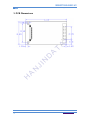
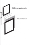
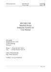
3. PCB Dimensions
User Manual
16
www.smartkit.co.kr