1
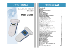
Model ZP In-Situ Oxygen Sensor (for use with PCC-III-Zxx0 Controllers) Instruction Manual Revision 1.3 6/24/04 Instruction Manual Part Number: 90179 Preferred Instruments A Division of Preferred Utilities Mfg. Corp. 31-35 South St., Danbury, CT 06810 Ph: 203-743-6741 Fax: 203-798-7313 www.preferred-mfg.com Preferred Utilities Manufacturing Corp. (PUMC) is an engineering-based manufacturer of combustion control and data acquisition systems, instrumentation, fuel handling systems, specialty burners, nuclear power plant outage support tools and component parts for industrial, institutional, and commercial power plants. Our Core Business is Combustion Control Systems. Preferred's headquarters is located in Danbury, CT, with direct sales and service offices located in the Boston, Chicago, New York, New Jersey, and Washington D.C. areas. Sales representative organizations cover all of the other major markets throughout the United States. Call 203-743-6741 or visit www.preferred-mfg.com for the WARNING The ZP Oxygen Sensor is an input to a PCC-III controller. The User must also consult the PCC-III Instruction Manual. The PCC-III is commonly used to control potentially dangerous Combustion and Chemical Processes. Only qualified Instrument Engineers or Technicians who have read the ZP and PCC-III Instruction Manuals, and are familiar with all aspects of the Process being controlled, and are aware of the particular Blockware Control Logic in the PCC-III at the site should attempt to reconfigure the Blockware Control Logic contained in the memory of a PCC III Controller. PCC-III Blockware Control Logic is field configurable and can be created or modified by the systems integrator, field start-up technician, or on-site personnel. The user must obtain and maintain accurate Blockware Control Logic documentation that reflects the actual on-site control logic. Do NOT assume that any Blockware Control Logic examples shown in this manual are used in the on-site PCC-III. VERIFY THAT THE PROCESS BEING CONTROLLED HAS BEEN SAFELY SECURED, ISOLATED, OR BYPASSED (AS REQUIRED BY THE SITE CONDITIONS) BEFORE MODIFYING ANY OF THE BLOCKWARE DATA IN ANY BLOCK IN THE PCC-III MEMORY, AND BEFORE CALIBRATING OR SHUTTING DOWN THE OXYGEN SENSOR. FAILURE TO COMPLY WITH ALL OF THE ABOVE CAN RESULT IN EQUIPMENT DAMAGE, INJURY, OR DEATH. The information in this document is subject to change without notice. Copyright 2002 PUMC All Rights Reserved. Table of Contents SYSTEM OVERVIEW Oxygen Sensor Detector Measuring Principle Probe “Z” Option Board (P/N 190371) “Z” board diagnostic LED’s: INSTALLATION Location Mounting Nipple and Flange Check Flange Temperature Check Flange Temperature Rotating the Probe to Lower Flange Temperature Calibration Gas Tubing Mount PCC-III Controller Wiring CALIBRATION ZP Oxygen Sensor Semi-Automatic Calibration Procedure ZP Calibration Error Messages: PCC-III BLOCKWARE FOR THE ZP SENSOR AND Z OPTION BOARD F6 2 3 3 3 4 5 5 6 6 6 6 7 7 8 9 9 10 10 12 13 [ZAIN] Zirconium Oxide Oxygen Analyzer Analog Input Block Outputs: AABO and DABO Auxiliary Block Outputs: ZAIN Blockware Inputs and Parameters: F4 [AABO] Analog - Auxiliary Block Output F94 [DABO] Discrete - Auxiliary Block Output ZP Oxygen Sensor Diagnostic Codes Automatic Calibration: Auto-Calibration Cycle: Automatic Calibration Diagnostic Codes 14 14 14 14 15 15 16 17 17 18 HANDLING, OPERATION, AND MAINTENANCE 19 Handling Precautions: Operation Boiler Start-up and Shut-down: Insertion into a Hot Stack or Duct: Powering-Down a ZP: Maintenance Inspect and Clean the Detector Filter and the Probe Cleaning the Detector and Probe Changing Filter TROUBLE SHOOTING ZP “Wet” Measurement vs. “Dry” Measurements Diagnostic Codes Normal Operating Values: Slow Response Time: Reading is Higher than Expected: Reading is Lower than Expected: Cell will not come up to Operating Temperature: Low Calibration Gas Flow Rate: Detector Leak Test: PARTS: Model ZP Oxygen Sensor Instruction Manual (rev. 1.3) 19 19 19 19 19 20 20 20 20 20 20 21 21 21 22 21 22 22 23 24 Page 1 Model ZP Oxygen Sensor Detector PCC-III-Zxx0 Controller Probe 190130 Connecting Cable Power Supply Calibration Gas Connection at Grade Level ZP-20 Oxygen Sensor and PCC-III-Zxx0 Controller Unit System Overview Monitoring flue gas oxygen levels minimizes fuel expense and insures safe combustion for all combustion processes. For Low NOx Burners that utilize Flue Gas Recirculation (FGR), windbox oxygen monitoring provides accurate feedback of the FGR/air ratio for stable NOx control. A model ZP Oxygen Analyzer System consists of: ZP Oxygen Sensor, 190130 connecting cable, type “Z” PCC-III I/O expansion option board, and a PCC-III Controller (see above). The “Z” plug-in option board is mounted inside the PCC-III controller, and can be factory or field installed. The PCC-III can accept up to two “Z” option boards and therefore, two ZP Oxygen Sensors. The Model ZP detector is an in-situ, direct insertion, Zirconium Oxide element with proven accuracy and long term stability. The Heater is a reliable ceramic element. The detector uses ambient air (instead of plant compressed air) for it’s reference, so it is immune to damage caused by water and oil in compressed air systems. The ZP is suitable for use in processes fired by gas, all grades of oil, and process off-gasses. A standard 3” flange is used to mount the ZP probe. The sample gas filter can be cleaned without removing the probe from the stack. The Detector can be repaired or replaced without removing the probe from the stack. The ZP Oxygen Probe is directly wired to the PCC-III Controller (eliminates a field mounted transmitter), which simplifies installation. The microprocessor based PCC-III Controller provides digital zirconia cell temperature control, electrical isolation, diagnostics and multiple alarms. Calibration is simple: connect the test gas and press a button. An optional, unattended, automated, two point calibration gas manifold with gas availability feedback is available for EPA CEM applications. The PCC-III Blockware Control Logic can use the % Oxygen Input(s) for any or all of the following purposes: Oxygen Trim control of fuel-air ratio, Windbox %FGR Control, multiple ZP sensor averaging, Alarming, Front Panel numeric and/or bargraph indication, 4-20 mA re-transmission, or RS485 Modbus into a SCADA system. The Blockware Control Logic loaded into the memory of each individual PCC-III controller determines how the Oxygen Input(s) are used. Preferred Instruments offers a wide variety of standard off-the-shelf Blockware Control Strategies for all common Combustion Control Applications (jackshaft, parallel positioning, VFD fan control, full metering, steam flow-air flow for solid fuels, Windbox % FGR, …). Users, Instrument and Combustion Technicians, or Systems Integrators trained in PCC-III Blockware Configuration can modify the Standard Blockware or create their own custom Blockware to suite on-site requirements. For a complete understanding of the Oxygen Analyzer System, and operation of the PCC-III, the user must obtain the site-specific PCC-III Blockware Documentation, and the PCC-III Instruction Manual. Model ZP Oxygen Sensor Instruction Manual (rev. 1.3) Page 2 Oxygen Sensor The ZP Oxygen Sensor is pre-assembled and consists of a Detector and a Probe. The ZP Sensor is field installed into the boiler flue gas outlet to sense flue gas oxygen concentration. The Oxygen Sensor is a direct sampling INSITU type and does not require an extractive sampling system. Detector The detector consists of a zirconia oxide cell, a ceramic heater with thermocouple, terminals for connecting to the Controller Unit, a flange for connection to the probe, an opening to accept reference (ambient) air and a connection for calibration gas. The detector works on a principle that when heated to 800 C (1472 ºF), the cell generates an electrical signal directly related to the oxygen concentrations of the flue gas. Flue gases are passed through a filter to prevent dust and dirt from contaminating the cell. Calibration gas can be injected into the space behind the ceramic and quartz filters to allow on-line calibration wihtout removal from the stack. Measuring Principle Zirconia (ZrO2) ceramic sintered with a small amount of yttria (Y2O3) is a solid electrolyte with oxygen ion conductivity at temperatures above 500 Deg. C. A solid electrolyte tube coated with porous platinum on both surfaces acts as an oxygen sensor. The differential oxygen concentration (% flue gas oxygen vs. % room air oxygen) in contact with both platinum electrodes produces a voltage as follows: E = RT/ 4F * ln (P1/ P2) R F T P1 P2 : : : : : Gas Constant Faraday Constant Temperature of Electrodes (Deg.K) Reference Air Oxygen Concentration Measured Oxygen Concentration For example, when the sensor element is heated to 800 Deg. C, Reference Oxygen (P1) = 20.6%, and the Measured Oxygen (P2) = 2.0% , an output signal of about 54 mV is generated. Lower Measured Oxygen levels produce higher voltage levels. A ceramic heater with type R thermocouple temperature feedback is used to maintain the zirconia oxygen sensor at precisely 800 C (1472 F). The PCC-III’s “Z” option board monitors the thermocouple, and regulates the power applied to the heater. Model ZP Oxygen Sensor Instruction Manual (rev. 1.3) Page 3 Ambient air provides the oxygen for the Reference side of the cell. Air circulates around the Reference electrode of the zirconia element. The air is rapidly circulated by convection because the sensor is very hot, and the gas volume is small. The sample gas reaches the measuring electrode by rapid convection in a manner similar to the Reference electrode. When troubleshooting a Zirconium Oxide Oxygen Analyzer, it is important to remember that the cell makes a differential measuerment. Said another way, the cell compares the unknown oxygen percentage in the flue gas against the "known" oxygen percentage in the ambient air inside the cell. Ambient air typically is 20.6%; however, it can range from 19.5% to 20.9% as relative humidity and temperature change. If the flue gas duct is pressurized, and a duct leaks allow flue gas to enter the detector head, the ambient oxygen percentage can be substantially lower. Combustible gasses in the ambient air will consume the oxygen on surface of the cell and will also lower the percent oxygen in the ambient air inside the cell. If the ambient oxygen percentage is low, a Zirconium cell will sense a lower differential and will cause the analyzer to indicate a higher oxygen level than is actually in the flue gas. Probe The probe is a stainless steel assembly that mounts on a 3 inch 125 lb flange (flat face) located on the flue gas duct or stack. The probe protrudes into the flue gas stream, and directs boiler flue gases from the middle third of the flue gas stream to the detector. The probe design provides for the removal of the detector for service or replacement without the need for probe removal. The probe is installed such the tip of the probe functions as a scoop when in the flue gas flow. The probe utilizes the dynamic differential pressure produced by the flue gas velocity and the probe tip as the means to move the flue gas through the probe. The probe internal pressure drop is very low and high velocity sample gas flow is provided to the detector, even when mounted vertically or upside down. Oxygen Sensor Gas Flow The ZP probe must always be horizontal or pitched down (away from the detector) to prevent accumulation of condensed flue gas water at the Detector. Flue gas contains a significant amount of water vapor. If liquid water comes in contact with the cell (heated to 800 C), the ceramic will crack and will have to be replaced. This is true for all brands of zirconium oxide Oxygen Analyzers. Model ZP Oxygen Sensor Instruction Manual (rev. 1.3) Page 4 “Z” Option Board (P/N 190371) The “Z” option board is plugged into either of the two option board slots in a PCC-III controller. Two “Z” boards and ZP probes may used in one PCC-III. The Block diagram below shows the functions that the “Z” board performs: Cell Temperature Control, Signal A/D converter, Cell Impedance Testing, Detector and field wiring diagnostics logic and LED indicators, Calibration Data Storage, and Electrical isolation of all ZP parts from the PCC-III. PCC-III "Z" Option Board (P/N 190371) optocoupler AND CPU connector Fuse Phase Angle Modulated Watchdog Timer 39 H 40 N 120 Vac 60 Hz Heater Control optocoupler RESET Microprocessor zero cross detector 41 42 Isolated Line Voltage Isolated Low Voltage ZP-xx Oxygen Probe 1 2 2.5 Vdc Heater G 43 A/D Converter 3 channel 16 bit, 150 mV FS optocouplers 44 DS1 CPU OK 45 46 Cell Impedance Test Relay K1 Isolated Circuits PCC-III Circuits DS3 Diagnostic Code + Isolated Power Supply - Fig. x-x 3 - 4 - 5 + 6 + - Type R T/C ZrO2 Cell + K1 DS2 @ TEMP. Cal. Data EEPROM & CJC Temp. Sensor + 47 + + 48 - - Optional Flue Gas Temperature Sensor TYPE J T/C Note: Some wiring is omitted for clarity. Refer to the Installation Section for complete field wiring details. Functional Block Diagram of "Z" Option Board with ZP Oxygen Probe “Z” board diagnostic LED’s: DS1 blinks to show that the “Z” board microprocessor is functioning. DS2 is ON when the Cell is at operating temperature, and blinks while warming up. DS3 is OFF when the ZP is operating normally. DS3 blinks 1-10 times if a problem exists. See the Diagnostic Codes on page 16 for the explanations of the DS3 Diagnostic LED blink codes. Optical Isolators 120VAC Heater Fuse Heater Triac DS3 Diagnostic Code DS2 Blinking Light - Warming Up Solid Light - At Temperature T/C Cold Junction Sensor & Calibration Data EEPROM Isolated DC Power Supply 50/60 Hz Noise Filters DS1 uP Run A/D with 10db DSP Noise Filter Model ZP Oxygen Sensor Instruction Manual (rev. 1.3) Page 5 Installation Note: The ZP Sensor and the “Z” option board are factory calibrated as a matched pair. The Sensor and “Z” board are marked with the same serial number. Install and wire the ZP Sensor and PCC-III “Z” board as a matched pair. CAUTION - FRAGILE: DO NOT DROP the Detector. If the ceramic zirconium oxide cell inside the detector is cracked, it must be replaced. The general Installation procedure is: Select a stack location Mount a pipe nipple and 3” - 125# flat faced flange on the duct. (nipple & flange supplied by others) Mount the ZP Sensor on the flange. Check the Flange Temperature. Run ¼” calibration gas tubing to floor level. Mount the PCC-III controller Run conduit from the PCC-III to the ZP (with flexible “service loop” at the ZP). Pull 190130 cable through the conduit and terminate the wiring. Location Locate the end of the probe in the middle one third of the flue gas stream as shown below and approximately perpendicular to the flue gas flow. The location must be upstream of any ambient air infiltration (and thus oxygen) caused by stack leaks. The probe should be located in an area free from any abrupt variations in flue gas pressure or temperature and flow stagnation pockets. The probe should be mounted in an area of uniform flue gas flow. The Probe should not be subjected to excessive vibration. The standard ZP is designed for indoor use. If located outdoors, purchase and install the optional Rain Cover. The detector uses ambient air as a reference, air containing abnormal oxygen levels causes measuring errors. Make sure that flue gas is not leaking out in the vicinity of the probe. The ZP probe must always be horizontal or pitched down (away from the detector) to prevent accumulation of condensed flue gas water at the Detector. Flue gas contains a substantial amount of gaseous water. The ceramic detector cell operates at 800 C (1472 F), if liquid water comes in contact with the cell, the ceramic cell will damaged. The Probe should not be vertical, and should not be pitched down more than 45º, to avoid overheating the mounting flange and internal seals. Mounting Nipple and Flange The 3” – 125# flat faced mounting flange must be mounted on an exposed, non-insulated, nipple as shown in the diagram below. This nipple cools the flue gas to prevent overheating the Detector Head. The ZP Detector flange must be less than 260 F in order to prevent damage to the calibration gas and ambient air seals within the Detector head. The mounting flange bolt holes should be installed so that the ZP flow arrows are aligned with the flue gas flow. This allows the end of the probe tip to function as a scoop when in the flue gas flow. The tip is designed to direct the flue gas to the detector by utilizing the dynamic differential pressure produced by the probe tip. The ZP Sensor flange has 8 bolt holes, but only 4 will be used. The extra 4 holes allow the user to rotate the probe after installation (see below). Probe Length = 20, 30, 45, 65 or 90" 2 1/4" dia. 3" - 125lb flange (flat face) 4 3/4" Termination Box 1/3 1/3 1/2" FNPT 1/3 Minimum Exposed Nipple Length Stack Width Insulation Model ZP Oxygen Sensor Instruction Manual (rev. 1.3) Calibration gas (1/4" Compression) Length Stack 6" 0 - 500 F 9" 500 - 750 F 12" 750 - 1000 F Page 6 Check Flange Temperature The ZP Detector flange temperature must be less than 260 F in order to prevent long term damage to the calibration gas and ambient air elastomer seals within the Detector head. After the ZP is bolted to the duct mounting flange, the burner should be operated for enough time for the ZP Detector flange temperature to stabilize (typ. 20-40 min.). Observe the temperature sensitive label on the Detector flange (see below). Temperature Under 260 Deg F Temperature Above 260 Deg F Temperature Sensitive Labels If the duct is insulated, and the nipple and flange are not insulated, and the proper nipple length is used (see chart in Installation sketch), the Detector flange temperature will not exceed 260 F. If the Detector temperature exceeds 260 F, use one or all of the following to lower the temperature: ♦ ♦ ♦ Reduce duct Radiant heating by insulating exposed ductwork. Add another flange gasket Rotate the probe one bolt hole to reduce flue gas flow to the detector. NOTE: The temperature sensitive label can NOT be re-used if the temperature exceeded 260F. Use a new label or some other means (thermocouple, surface thermometer, …) to measure the temperature after modifications are made. Rotating the Probe to Lower Flange Temperature If the flue gas velocity in the duct is unusually high, the higher flow rate through the probe and past the Detector can cause Detector over heating. Rotating the probe flange one bolt hole to purposely mis-align the probe tip will reduce the flue gas flow rate through the probe. If the probe is horizontal, rotate it counter-clockwise. The detector has an opening for atmospheric air on the lower left side of the Detector housing. Rotating counter-clockwise will keep the inlet pointing downward, minimizing the possibility of water infiltration. Rotating the Probe ONE Bolt Hole To Lower Detector Flange Temperature Normal Orientation Model ZP Oxygen Sensor Instruction Manual (rev. 1.3) High Temperature Orientation Page 7 Calibration Gas Tubing When the detector is installed, the detector calibration gas inlet fitting and tubing should slope downwards to prevent the entry of condensed water into the Cell. Install copper tubing from the calibration gas port down to an easily accessible location. Terminate the end with a valve, cap plug, ZP-Cal assembly, or other means to positively prevent ambient air infiltration into the calibration gas port. Model ZP Oxygen Sensor Instruction Manual (rev. 1.3) Page 8 Mount PCC-III Controller Mount the PCC-III Controller in a location that is easily accessible to the operator and no more than 500 ft of wiring distance from the ZP Sensor. The location must be free from vibration, extreme temperatures (32 - 122 F), and condensing humidity. The PCC-III Controller front panel is rain proof but should not be subjected to prolonged direct sun light. Use the full size panel cut-out template provided to help cut the hole in the panel. Wiring The PCC-III and ZP 120 Vac power supplies should only be turned off for ZP maintenance or for extended Boiler shutdowns. The 120 Vac power should NOT be turned off every time the burner is shut down. Excessive power cycling can shorten the life of the ZP detector. Provide a “service loop” in the flex conduit at the Detector to allow removal disconnecting the wiring. Note: The Terminal Screws in the Detector head are M4x0.7 metric screws. The ZP Sensor and the “Z” option board are factory calibrated as a matched pair. The Sensor and “Z” board are marked with the same serial number. Install and wire the ZP Sensor and PCC-III “Z” board as a matched pair. PCC-III "Z" Option Board 120 Vac 70W 60 Hz H x-39 N x-40 G x-41 P/N 190130 7 W ire Cable Internal 3 Am p Fuse note 1 ZP-xx Oxygen Probe R W x-42 note 2 G S x-43 Type R Green x-44 T/C W ire Cable note 3 1 S Gray Cable x-45 2 Heater G B 3 R 4 B 5 R 6 W + R - + Type R T/C - ZrO 2 Cell + x-46 note 4 note 6 note 5 x-47 TYPE J x-48 T/C WIRE note 7 TYPE J T/C Optional Flue Gas Tem perature Sensor (P/N 104087) Notes: 1. Run all wires in one conduit. 500 ft. maximum wiring length. Avoid splices. Use only Preferred Instruments P/N 190130 cable between the ZP and PCC-III. The twisted shielded Cell and T/C wire with twisted AC wiring prevents electrical noise. Multiple ZP cables may be run in one conduit. Flue Gas Temperature wire can be in this conduit, if shielded T/C wire is used. Do not include any other AC or DC wires in this conduit. 1/2" conduit or larger is required for one 190130 cable. 2. Connect Detector Ground wire directly to Power Supply Ground (16 ga. min.) 3. Connect a separate signal shields Ground wire directly to Power Supply Ground (22 ga. min.). The "S" terminals are connected internally. 4. Connect shields to "S". Insulate shields to prevent shorts to the case or other shields 5. Do not connect shields at the sensor. Insulate shields to prevent shorts to the case or other shields. 6. "x" = 1 or 2. Indicates which PCC-III option slot is being used. 7. Flue Gas Temperature (FGT) Sensor is optional, Jumper Input if not used. Shielded cable is not required if run in conduits that do not have: ZP probe wires, AC wires, or noisy DC wiring. Model ZP Oxygen Sensor Instruction Manual (rev. 1.3) Page 9 Calibration WARNING If the ZP sensor is part of an Oxygen Trim Combustion Control system or any other automatic control system, the control system must be disabled, bypassed or placed in Manual by a qualified control system technician before applying any test gas to the ZP Detector. Failure to do so could result in equipment damage, injury, or Death. The ZP analyzer and PCC-III “Z” option board are factory calibrated as a matched pair. If a new Sensor and PCC-III “Z” board are installed as a matched pair, field calibration is not required. Calibration data is stored in a non-volatile EEPROM memory located on the Z Option Board (not in the CPU board EEPROM). Due to the excellent stability of the detector, there is very little drift even over long periods of time. Six to twelve month calibration checks are normal for natural gas and #2 diesel fuel oil fired units. Fuels with high sulfur, heavy metals or other contaminants should be checked every three to nine months. The main indicator for the need for re-calibration is Cell Impedance. If the Cell Impedance AABO Block is configured, note and record the Cell Impedance during Start-up and after each re-calibration. Re-calibrate again after Cell Impedance increases another 100-200 ohms. The ZP Oxygen Sensor can be checked or calibrated without being removed from the stack, and without shutting down the burner. To check for proper operation, simply apply a known concentration test gas at 2-3 SCFH (at 1-5 psig) to the ¼” compression fitting at the bottom of the ZP Detector. A single Test Gas can be used to check the operation of the ZP Sensor and Z Board. Two certified Test Gasses are required in order to Calibrate a ZP Sensor / Z board pair. ZP Oxygen Sensor Semi-Automatic Calibration Procedure Obtain two cylinders of certified calibration gas, a 0-30 psi pressure regulator, a 0-5 SCFH rotometer flow meter, ¼” tubing and compression fittings. The Low Range Calibration Gas must be between 0.300% and 3.000% oxygen mixed with dry nitrogen. 1-2% is typical for combustion applications. The High Range Calibration Gas must be between 7.000% and 19.000% oxygen mixed with dry nitrogen. 8% is typical for combustion applications, 18% for FGR ratio (Flue Gas Recirculation) applications. Calibration Test Gas that is tested and certified to be within +/- 2% of labeled Oxygen concentration can be obtained from Preferred Instruments (203-743-6741) or Scott Specialty Gases (800-217-2688). Obtain the site specific PCC-III Blockware drawing for your controller to determine the Block number of the ZAIN Block that is controlling this ZP Sensor (there can be two ZP sensors connected to one PCC-III). Obtain the calibration gas factory certification test results to determine the actual oxygen concentration in each cylinder. Using the PCC-III Front Panel Edit Menus or PC3_Edit or PC3_Draw, enter the certified values (not the nominal values) into Parameter 3 (LOW % O2 CAL GAS) and Parameter 4 (HIGH % O2 CAL GAS) of the ZAIN Block. Apply 120 Vac power to the PCC-III “Z” board. Wait 5-10 minutes for the Cell temperature to come up to the 800 C operating temperature. Verify that the System is operating properly by one of the following methods. Remove the PCC-III front door and verify that the Z board top LED is OFF (DS3, see page 5). If the Diagnostic Code AABO Block is used in the Blockware, either view the code on the Front Panel Display, or use EXAMINE mode to view the Block Output (0 = Normal, 15=Not at operating temperature, see table for other codes). Verify that the Cell is “At Temperature” by one of the following methods. Remove the PCC-III front door, the Z board middle LED should be ON and not blinking (DS2, see pg 5). If the Cell Temp AABO Block is used in the Blockware, either view the temperature on the Front Panel Display, or use EXAMINE mode to view the Block Output (80% = 800C). Model ZP Oxygen Sensor Instruction Manual (rev. 1.3) Page 10 Wait an additional 15 minutes after the Cell is At Temperature to allow the Detector internal temperatures to stabilize. Connect the Low Range Calibration Gas cylinder and flow meter to the Detector. Place the PCC-III into service manual mode (S/M). PCC-III Key strokes: EDIT EDIT W to “EXIT S/M” then ENTER at “ALL S/M” press ENTER “EXIT S/M” is displayed again. Activate the Oxygen Calibration Menu Item. EDIT W to “CALIBRATE I/O” then ENTER EDIT W to “BOARD x OXYGEN INPUT” then ENTER “OPEN L.LLL% GAS VALVE, PRESS ENTER AFTER OPENING” will be displayed. “L.LLL%” should be the exact concentration of Cal. Gas as entered in ZAIN Parameter 3. The “Normal Operation” DABO output changes from 1 to 0 The “Calibration in Progress” DABO output changes from 0 to 1 Open the Calibration Gas valve. Verify a flow of 2 – 3 SCFH of gas to the Detector. Press ENTER “signal settling” is displayed for a short time. “y.yyy% change” is displayed and updated until the cell mV signal stabilizes. It can take 2 to 5 minutes for the signal to stabilize. Less than 0.015% change for 15 seconds is required. Press ESC to abort if the signal never stabilizes (due to electrical noise, line voltage variations, low gas flow, or gas leaks) “CLOSE LOW VALVE, OPEN HH.HHH% GAS VALVE, PRESS ENTER AFTER OPENING” is displayed after the signal stabilizes. “HH.HHH%” should be the exact concentration of Cal. Gas as entered in ZAIN Parameter 4. Close the Calibration Gas Valve. Disconnect the Low Range Calibration Gas. Connect the High Range Calibration Gas cylinder and flowmeter to the Detector. Open the Calibration Gas valve. Verify a flow of 2 – 3 SCFH of gas to the Detector. Press ENTER “signal settling” is displayed for a short time. “y.yyy% change” is displayed and updated until the cell mV signal stabilizes. It can take 2 to 5 minutes for the signal to stabilize. Less than 0.015% change for 15 seconds is required. Press ESC to abort if the signal never stabilizes (due to electrical noise, line voltage variations, low gas flow, or gas leaks) “CLOSE CAL GAS VALVE. PRESS ENTER WHEN CLOSED” is displayed after the signal stabilizes. Close the Cal Gas Valve. Press ENTER “purging cal gas” will be displayed for 10 seconds. This allows the Cal Gas to be purged from the Detector by the Flue Gas. “calibration successful. ESC to exit” is displayed at the completion of purge. Calibration is completed. The “Normal Operation” DABO output changes from 0 to 1 The “Calibration in Progress” DABO output changes from 1 to 0 Press ESC to return to the CALIBRATE I/O menu. Press ESC to return to the BOARD x OXYGEN INPUT display EDIT V to the EXIT S/M display, Press ESC to exit S/M mode. Cap off, plug, or close a valve to prevent room air from entering the calibration gas tubing and/or port of the ZP Detector. Infiltrating air will cause the ZP to read higher than actual Oxygen Levels. Model ZP Oxygen Sensor Instruction Manual (rev. 1.3) Page 11 ZP Calibration Error Messages: ERROR: MUST BE IN S/M TO CALIBRATE The PCC-III must be in S/M (Service Manual) mode before activating the Calibration cycle. ERROR: AUTO CAL IN PROGRESS A Semi-Automatic Calibration from the PCC-III Front Panel can not PRESS ESC occur while an Auto-Calibration cycle is in progress. ERROR: BAD Z OPTION BOARD PRESS The Z Option Board is not communicating with the CPU board. Verify ESC that board is properly plugged in. Replace if required. ERROR: T/C OPEN PRESS ESC Check Cell thermocouple field wiring and Detector for an open circuit. ERROR: T/C REVERSED PRESS ESC Check Cell thermocouple field wiring. ERROR: T/C SHORT PRESS ESC Check Cell thermocouple field wiring. ERROR: FUSE OPEN / NO POWER Check Z board 120 Vac power input and Z board fuse PRESS ESC ERROR: CELL OPEN OR COMBUSTIBLES Cell mV input is above 130 mV. PRESS ESC If Cell is cold, wait for Cell to Warm-up. Check Cell field wiring and Detector for an open circuit. Are Combustibles present in the Flue Gas? ERROR: CELL IMPEDANCE = xxx, MUST If Cell is > 2 years old, replace the Detector assy. BE < 1100 PRESS ESC If Cell is new, check wiring for loose connections. ERROR: CELL NOT AT TEMPERATURE Wait for Cell Temperature to stabilize at 800C. PRESS ESC ERROR: CELL uV TOO LOW. PRESS ESC The Cal Gas Oxygen Content was too high, or Cal Gas flow was too low, or Outer filter is cracked and Cal gas is escaping, or Ambient air was leaking into the Cell. WARNING: XX.XX% GAS vs ZZ.ZZ% The old calibration indicates that the Cal Gas MAY be incorrect. Check “uV TOO LOW” errors above, if OK, press ENTER to accept. PROBE (EXISTING CALIBRATION). Check displayed Oxygen % against a third Cal. gas or a portable PRESS ESC to exit, or ENTER to accept analyzer after the completion of the calibration. ERROR: CELL uV TOO HIGH. PRESS The Cal Gas Oxygen Content was too low, or [ESC] The Cal Gas contains combustibles, or Cell wiring partially open. WARNING: IS CAL GAS=HH.HHH% ??? The old calibration indicates that the Cal Gas MAY be incorrect. ESC=abort, ENTER=accept or to exit Check “uV TOO HIGH” errors above, if OK, press ENTER to accept. Check displayed Oxygen % against a third Cal. gas or a portable analyzer after the completion of the calibration. ERROR: xx.xxx mV/decade SLOPE IS OUT The Cal Gas % Oxygen values are incorrect in the ZAIN Parameters 3 OF RANGE. [ESC] to exit & 4, or The Cal Gas is marked incorrectly, or The Detector is old or damaged and needs to be replaced. ERROR: x.xxx% CELL OFFSET IS OUT OF The Cal Gas % Oxygen values are incorrect in the ZAIN Parameters 3 RANGE. ESC to exit & 4, or The Cal Gas is marked incorrectly, or The Detector is old or damaged and needs to be replaced. ERROR: xxx deg C CELL TEMP IS OUT OF The Cell Temperature drifted out of range during the Calibration cycle. RANGE. [ESC] to exit Check wiring, Check for 120 Vac line noise. After any of the above error messages are displayed, or is the Calibration is aborted with the ESC button, the Cell must be purged. The Following messages will be displayed if the calibration is unsuccessful: “CLOSE CAL GAS VALVE. PRESS ENTER WHEN CLOSED” is displayed. Close the Cal Gas Valve. Press ENTER “purging cal gas” will be displayed for 10 seconds. This allows the Cal Gas to be purged from the Detector by the Flue Gas. “purge complete. ESC to exit” is displayed at the completion of purge. The Sensor resumes operation using the calibration data that existed before this calibration was attempted. The “Normal Operation” DABO output changes from 0 to 1 The “Calibration in Progress” DABO output changes from 1 to 0 Press ESC to return to the CALIBRATE I/O menu. Press ESC to return to the BOARD x OXYGEN INPUT display EDIT V to the EXIT S/M display. Press ESC to exit S/M mode. Model ZP Oxygen Sensor Instruction Manual (rev. 1.3) Page 12 PCC-III Blockware for the ZP Sensor and Z Option Board This section provides engineering information on Blockware Functions ZAIN, AABO, and DABO that are specific to the PCC-III “Z” option board and the ZP Oxygen Analyzer. These Blockware functions require PCC-III CPU ROM software version 3.0 or higher, and CPU hardware rev. D or higher. WARNING: If the ZP analyzer is used as part of an automatic combustion control system (for example oxygen trim for ratio control), the BlockWare must utilize the DABO “Normal Operation” status as a safety interlock. The control logic designer must determine and program appropriate system response after an analyzer failure. All zirconium cells have a limited life of two to five years of use, and typically fail by indicating a higher than actual Oxygen concentration. Failure to do so can result in equipment damage, injury or Death. Refer to the PCC-III Instruction Manual for information on all other PCC-III Blockware control logic, controller operation, and safety precautions. An example of Blockware for a ZP sensor is shown below: Oxygen Analyzer ZAIN ch. 1-1 0-10% OXYGEN 21 DIS CH 1 PV BG 1 SP BG 1 Oxygen AABO Flue °F DIS CH 2 AABO MB CELL TEMP 81 PV FLUE GAS TEMP 80 PV MB HIALM HIALM 1=DE 49 1=DE 50 Cell °C DIS CH 3 ALM 2 ALM 1 High Flue Temp. Alarm AABO MB CELL OHMS 82 Cell Imp. DIS CH 4 ROUT NO 8U ch. 0-2 C 7U INVERT 148 NC 6U High Flue Temp Shutdown AABO MB DIAG CODE 83 DABO MB Diag. DIS CH 5 Cell OK NOT NORMAL Cell Fault ALM 3 85 84 ALM 4 LOALM PV 1=DE 56 LED MID. RIGHT 76 Model ZP Oxygen Sensor Instruction Manual (rev. 1.3) DOUT PS 4 ch. 0-1 OC 5 143 Low Oxygen Alarm 9 Page 13 F6 [ZAIN] Zirconium Oxide Oxygen Analyzer Analog Input Function ZAIN is the Blockware interface to the PCC III “Z” option board and the ZP Oxygen Detector. There can be up to two “Z” option boards in a PCC-III, Parameter 1 specifies the slot . Parameter 2 determines the scaling of the primary Block Output. The default is 10% oxygen cause a 100% Block Output. The Block Scaling can be changed at any time without having to re-calibrate the ZP Sensor. Parameters 3 & 4 are the Calibration Gas Concentrations, and are only used during the calibration cycle. The precise certified concentrations must be entered, do not enter the nominal concentrations. Block Outputs: Traditional PCC-III Blockware has only one Block Output value per Block. The ZAIN function has one Primary Block Output, and 11 Auxiliary Block Outputs (xABO). The Primary Block Output is the current Oxygen Concentration. AABO and DABO Auxiliary Block Outputs: There are 5 Analog Auxiliary Block Output (AABO) channels and 6 Discrete Auxiliary Block Output (DABO) channels listed below with the scaling and description of each channel. The Auxiliary Outputs are made available by soft-wiring the ZAIN Primary Output into multiple AABO and DABO Blocks. The “channel” Parameter in each AABO or DABO Block determines which ZAIN auxiliary output signal will become the output signal of each individual xABO Block. See the sample Blockware diagram below. ZAIN Blockware Inputs and Parameters: --------------------------------------------------------------------------------------------FUNCTION: 6 TEMP BYTES: 13 RETENTIVE BYTES: 0 DATA BYTES: 23 NAME: ZAIN SINGLE USE FUNCTION: N OUTPUT TYPE: A --------------------------------------------------------------------------------------------Input Type Description Notes 1 D ENABLE AUTO-CAL 1 2 D START AUTO-CAL CYCLE 2 3 D CAL GAS PRESSURE SWITCH 3 Parameter 1 2 3 4 5 Description Default OPTION BOARD (1-2) 1 SCALING: xx% O2 = 100% OUTPUT 10 LOW %O2 CAL GAS 0.400 HIGH %O2 CAL GAS 8.000 AUTO CAL TIMER HOURS (0=ON DEMAND) 24 Max 2 25 3.000 19.000 199 Analog Auxiliary Outputs 1 2 3 4 5 A A A A A Description FLUE GAS TEMPERATURE CELL TEMPERATURE CELL IMPEDANCE HOURS UNTIL NEXT AUTO-CAL DIAGNOSTIC CODE (0-100% (0-100% (0-100% (0-199% (0-100% Discrete Auxiliary Outputs 1 2 3 4 5 6 D D D D D D Description NORMAL OPERATION CALIBRATION IN PROGRESS AUTO CAL PASSED AUTO CAL FAILED OPEN LOW CAL GAS OPEN HIGH CAL GAS (1 (1 (1 (1 (1 (1 = = = = = = = = = = = Min 1 5 0.300 7.000 0 Code 3 3 2 2 1 Notes Notes 0-1000 F) 0-1000 C) 0-1000 ohms) 0-199 HRS) 4 CODE 0-100 see chart below) Normal) In Progress) Passed) Failed) Open Low Gas Valve) Open High Gas Valve) Notes 5 Notes: 1. 1 = Enable Auto Cal cycles. This input does not actually start the cycle. 2. A 0 to 1 (“rising edge) transition starts the Auto-Cal cycle. 3. Locate on the common pipe to the Detector. Proves Cal Gas is Present. 4. 0 = off, timer disabled. Input 2 is still active. 5. 1 = Normal. 0 = Not Normal, If a Calibration is in Progress, OR If Diagnostic Code: 1-9,15,30,50-52 is active (see page 16). Model ZP Oxygen Sensor Instruction Manual (rev. 1.3) Page 14 F4 [AABO] Analog - Auxiliary Block Output Function AABO allows the ZAIN Analog Auxiliary Block Outputs to be connected to other Blockware Inputs. The Input of the AABO must be soft-wired to a ZAIN Block. Parameter 1 is used to select the ZAIN Auxiliary Output signal that will become the Output signal of this AABO Block. See the ZAIN Block description for a list of the available Auxiliary Outputs and for the scaling of each Aux. Output. --------------------------------------------------------------------------------------------FUNCTION: 4 TEMP BYTES: 0 RETENTIVE BYTES: 0 DATA BYTES: 5 NAME: AABO SINGLE USE FUNCTION: N OUTPUT TYPE: A --------------------------------------------------------------------------------------------Input Type Description Notes _____________________________________________________________________________________________ 1 A or D MASTER BLOCK 1,2 Parameter Description Default Max Min Code Notes _____________________________________________________________________________________________ 1 AUX OUT CH. 0 x 0 3 3 Notes: 1. This is NOT a normal Block Input. This Input is the Master Block that will be used as the Source for the auxiliary output signals. There is no Input Type mis-match error checking, because the Master Block output value is not used by the AABO. 2. If the Input Block (ie, Master Block) does not have any Auxiliary Block Outputs, then the AABO Block Output = The Input current value (ie, Master Block Output). An error message is generated when you attempt to leave S/M mode. The PCC-III will not leave S/M mode until a proper Master Block is assigned. 3. The scaling, function, and quantity of auxiliary output channels is determined by the Master Block. F94 [DABO] Discrete - Auxiliary Block Output Function DABO allows the ZAIN Discrete Auxiliary Block Outputs to be connected to other Blockware Inputs. The Input of the DABO must be soft-wired to a ZAIN Block. Parameter 1 is used to select the ZAIN Auxiliary Output signal that will become the Output signal of this DABO Block. See the ZAIN Block description for a list of the available Auxiliary Outputs and for the scaling of each Aux. Output. DABO ch. 1 = 1 when the ZP Sensor and Z board are operating Normally. If he AABO Diagnostic Code equals 1-6, 8-10, 15, 30, or 50-52, or if a Calibration cycle is in process, the Normal Operation DABO changes to 0. Zirconium Oxide sensors have a limited life (typ 2-5 years). If the Oxygen signal is used as part of an automatic combustion control system, the Blockware Logic Designer must use the Normal Operation signal as an interlock that prevents a dangerous control response when the Oxygen Sensor fails. --------------------------------------------------------------------------------------------FUNCTION: 94 TEMP BYTES: 0 RETENTIVE BYTES: 0 DATA BYTES: 5 NAME: DABO SINGLE USE FUNCTION: N OUTPUT TYPE: D --------------------------------------------------------------------------------------------Input Type Description Notes _____________________________________________________________________________________________ 1 A or D MASTER BLOCK 1,2 Parameter Description Default Max Min Code Notes _____________________________________________________________________________________________ 1 AUX OUT CH. 0 x 0 3 3 Notes: 1. This is NOT a normal Block Input. This Input is the Master Block that will be used as the Source for the auxiliary output signals. There is no Input Type mis-match error checking, because the Master Block output value is not used by the DABO. 2. If the Input Block (ie, Master Block) does not have any Auxiliary Block Outputs, then the DABO Block Output = The Input current value (ie, Master Block Output). An error message is generated when you attempt to leave S/M mode. The PCC-III will not leave S/M mode until a proper Master Block is assigned. 3. The scaling, function, and quantity of auxiliary output channels is determined by the Master Block. Model ZP Oxygen Sensor Instruction Manual (rev. 1.3) Page 15 ZP Oxygen Sensor Diagnostic Codes AABO ch 5 provides a diagnostic code that indicates the current status of the ZP sensor and the Z board. For a listing of these codes, see the tables below Code Description Comments, Possible Causes 0 Normal Operation 1 CPU board is not communicating with Z Option Board Does the PCC-III BlockWare include a “ZAIN” block? if not, correct the PCC-III BlockWare. Does “ZAIN” Block Option Slot Parameter match the actual Z Option Board location (Slot 1 vs. Slot 2)? Check CPU / Option Board connector pin alignment If no other problem found, replace Z Option Board 2 Z Option Board A/D converter is bad Replace Z Option Board 3 Cell T/C Wire Open Check connections and T/C field wiring continuity. Repair field wiring. Check T/C continuity inside the Detector. If open, replace detector. 4 Cell T/C Wiring Reversed Correct field wiring. Black T/C wire is positive. Red T/C wire is negative. 5 Cell T/C Wiring Shorted Wait 30 seconds after power-up to allow heater to warm T/C, then re-check the Code Number. Disconnect T/C wires at detector. Check field wiring for wire to wire and wire to ground shorts. Correct wiring. Disconnect heater wiring at Z board and check field wiring and heater continuity The heater is typically 45-55 ohms. Correct wiring. If T/C is open, replace Detector. If Wiring & Detector are OK, replace “Z” option board. 6 Blown Fuse or No AC Power Verify that 120 Vac is present on term 39 & 40 of “Z” board Check F1 on “Z” board. 7 High Combustibles This code is invalid unless the cell is near operating temperature. Or Check the Flue Gas for Combustibles. Cell Wires Open Check continuity of field wiring. Check continuity of Cell. Cell must be warm before checking. Replace detector if open 8 T/C cold junction temperature sensor is bad Replace Z option board 9 high cell temperature Heater mis-wired. (heater turns off) High AC Line Voltage (Above 135 Vac). 10 Z board cell impedance test relay bad For New Detectors, Ignore Intermittent Code 10, this is not unusual due to low cell Impedance (a good thing). The test and this code are updated every 10 minutes Check for Excessive electrical noise on the Cell field wiring. For older cells, if Code occurs continuously, Replace z option board 11 Cell ohms > 1100 ohms Replace detector, cell is at end of life. 15 NOT at Normal Cell Operating Temperature (760 – 830 C) 50 Z board “slope” coefficient is bad. Default Data in use. Z Board was never factory calibrated 51 Z board “ambient % Oxygen” coefficient is bad. Default Data in Z Board was never factory calibrated use. 52 Z board “Calibration Cell Temperature” is bad. Default Data in Z Board was never factory calibrated use. 60 Flue Gas Temp (FGT) T/C Wire Open Flue Gas thermocouple wiring is open or not installed. Model ZP Oxygen Sensor Instruction Manual (rev. 1.3) Page 16 Automatic Calibration: Automatic Calibration is optional, and is typically only required for EPA Continuous Emissions Monitoring systems. Auto-Cal requires two permanently installed calibration gas cylinders with regulators, and electric solenoid valves, and a common rotometer flow regulator, and a Cal. gas pressure switch. DABO Blocks are used to link the ZAIN to PCC-III output channels that control the solenoid valves, and the Pressure switch is linked via a DIN to ZAIN input channel 3. Typically, the Auto-Cal cycle is triggered by the ZAIN Block ‘s internal timer every 24 hours. However, Auto-Cal can be triggered by Discrete Input 2. If the Input 1 (ENABLE AUTO-CAL) signal is Low, Auto-Cal is disabled. If the Input 1 (ENABLE AUTO-CAL) signal is High, Parameter 5 determines the Automatic Calibration cycle interval. Auto-Calibration Cycle: ZAIN timer or Input 2 triggers the start of the Auto-Cal cycle Normal Operation DABO changes to 0 Calibration in Progress DABO changes to 1 Open Low Cal Gas DABO changes to 1 Low Range Cal Gas starts to flow which closes the cal gas pressure switch. After the cell mV signal settles Open Low Cal Gas DABO changes to 0 ZAIN verifies that the valves closes when the cal gas pressure switch opens Open High Cal Gas DABO changes to 1 After the cell mV signal settles Open High Cal Gas DABO changes to 0 ZAIN verifies that the valves closes when the cal gas pressure switch opens ZAIN starts a 10 sec Cell Purge timer. Normal Operation DABO changes to 1 Calibration in Progress DABO changes to 0 Auto Cal Passed DABO changes to 1 10 seconds later, Auto Cal Passed DABO changes to 0 Throughout the Auto-Cal cycle the Diagnostic Code AABO changes to indicate the current status. If an error occurs at any point during the Auto-Cal cycle, the Auto Cal Failed DABO will change to 1 for 10 seconds and the Diagnostic Code AABO will indicate the Error Code for 10 seconds Model ZP Oxygen Sensor Instruction Manual (rev. 1.3) Page 17 Automatic Calibration Diagnostic Codes Code 0 30 31 32 33 34 35 36 37 38 39 40 41 42 43 44 45 46 Description Normal Operation Auto-Cal in progress Semi-Automatic Calibration already in progress, Auto-Cal aborted Cal. Gas pressure switch was ON before opening Low Cal Gas valve Low Cal Gas pressure was low Low Cal Gas timeout (signal did not stabilize within 6 minutes) Low Cal was > 4% oxygen (based on previous calibration data) Low Cal was > +/- 0.75% difference from last calibration Cal. Gas pressure switch was ON before opening High Cal Gas valve High Cal Gas pressure was low High Cal Gas timeout (signal did not stabilize within 6 minutes) High Cal was < 5% oxygen (based on previous calibration data) High Cal was > +/- 0.75% difference from last calibration mV/decade slope was out of range, Auto-Cal aborted. Cell Offset was out of range, Auto-Cal aborted. Calibration Cell Temperature is out of range, Auto-Cal aborted. Cal. Gas pressure switch is ON after closing High Cal Gas valve ENABLE Input turned OFF during Auto-Cal. Auto-Cal aborted. Model ZP Oxygen Sensor Instruction Manual (rev. 1.3) Comment Check solenoid vale and pressure switch operation. Check Cal Gas cylinder pressure. Check for electrical noise interference. Check Cal Gas value. Check Cal Gas value. Check solenoid vale and pressure switch operation. Check Cal Gas cylinder pressure. Check for electrical noise interference. Check Cal Gas value. Check Cal Gas value. Check cal gas values and cell impedance Check cal gas values and cell impedance Check solenoid vale and pressure switch operation. Page 18 Handling, Operation, and Maintenance Handling Precautions: CAUTION: The ZP flange and tip external surface temperatures approach 200 F when outside the stack or duct. When installed, Flue gas Temperatures can substantially increase the ZP surface temperatures. Always wear protective gloves to avoid burns. The Zirconium Cell, Cell Heater, and dust filters are all ceramic and can be damaged if dropped. Do not drop the ZP Sensor assembly or ZP Detector. Package with cushioning before shipping. Liquid water should not be allowed to come in contact with the Cell. Water vapor is not a concern. Liquid water that contacts a hot cell or heater can crack the element and destroy it. Calibration gas must be dry and tubing must slope down to prevent trapping condensation. Condensation can for water drops, observe start-up shutdown procedures below. Operation Internally, the Cell and Heater operate at 800 C (~1470 F). The system should remain powered up whenever possible. The Heater uses less than 70 Watts (typically 40-50 W). Do not subject the Detector to excessive heat-up and cool-down cycles. If the burner cycles more than once per day, the ZP should not be routinely powered-up and down every time the burner cycles on and off. Flue gas contains a substantial percentage of water vapor. Avoid water condensation in the Detector. If the Detector is hotter or the same temperature as the Flue gas, the water vapor can not condense. Boiler Start-up and Shut-down: If the ZP is kept in the stack, powered up, and kept at operating temperature, the burner can be started and stopped at any time without affecting the ZP. Because the Cell is at 800C, water will not condense inside the ZP Detector. Insertion into a Hot Stack or Duct: If a room temperature ZP is inserted into hot stack or duct, the “cold” metal of the ZP can condense the flue gas water vapor and form liquid water droplets inside the Cell or Heater. This can damage or corrode the ZP internals. Before inserting a ZP into a hot stack or duct, power-up the ZP and allow it to reach operating temperature, and then insert it into the stack. CAUTION: The ZP flange and tip external surface temperatures approach 200 F. Always wear protective gloves to avoid burns. Powering-Down a ZP: If both the Boiler and the ZP are being shut down: Shut down the boiler first, and keep the ZP powered until after the temperature inside the stack or duct has cooled down to it’s lowest normal off-line temperature. If the Boiler is going to remain in operation, or if you can’t wait for the stack to cool down: Leaving the ZP probe in the stack, cautiously remove ZP Detector from the probe flange with gloved hands and expose it to room air, and then power-down the ZP. If the duct pressure is positive, a cover plate and should be used to prevent flue gas flow through the open hole in the probe flange after the Detector is removed. Model ZP Oxygen Sensor Instruction Manual (rev. 1.3) Page 19 Maintenance See the Calibration section above for suggested calibration frequency. WARNING If the ZP sensor is part of an Oxygen Trim Combustion Control system or any other automatic control system, the control system must be disabled, bypassed or placed in Manual by a qualified control system technician before removing the Detector from the Stack or Duct. Failure to do so could result in equipment damage, injury, or Death. CAUTION: The ZP flange and tip external surface temperatures approach 200 F when outside the stack or duct. When installed, Flue gas Temperatures can substantially increase the ZP surface temperatures. Always wear protective gloves to avoid burns. Inspect and Clean the Detector Filter and the Probe Fuel Type: Solid Fuels and #6 oil #2 oil and off-gasses Natural Gas Frequency: every 3 months every 6 months every 12 months Cleaning the Detector and Probe Leaving the ZP probe in the stack, cautiously remove ZP Detector from the probe flange with gloved hands and expose it to room air, and then power-down the ZP. If the duct pressure is positive, a cover plate and should be used to prevent flue gas flow through the open hole in the probe flange after the Detector is removed. Using clean, dry, compressed air or nitrogen, blow air gently across the face of the filter (see pg. 2) at a 20-degree angle. Caution: Water in the air can damage filter. Using compressed air connected to a long tube, blow any dust inside the ZP Probe duct into the stack or duct. Changing Filter If the filter is clogged with dust, replace it with a spare filter. The filter assembly can be removed by turning it counter clockwise with a wrench. Trouble Shooting ZP “Wet” Measurement vs. “Dry” Measurements The most common “problem” encountered is that the ZP “% Oxygen” does not match the “% Oxygen” measured by a portable or extractive Oxygen Analyzer. This is normal and the two measurements should NOT be the same. Wet Measurement (ZP): The ZP Detector Cell is located inside the Flue Gas and measures Oxygen as a percentage of all of the total flue gas component gasses (O2, N2, CO2, CO, H20). This is known as a “Wet” oxygen measurement, because the water vapor occupies a substantial percentage of the total volume of the flue gas. Dry Measurement (Portable & Extractive): A portable oxygen analyzer or an EPA CEM oxygen analyzer extracts a sample of the flue gas from the duct and transports it to a measurement device that is located outside of the duct. Since the temperature of the connecting tubing and/or the external measurement cell is below the dew point (that is, condensation temperature) of the water vapor in the flue gas sample, the water vapor in the flue gas condenses. This is know as a “Dry” oxygen measurement, because the condensed water occupies a negligible percentage of the total volume of the flue gas. Effectively, a portable or other extractive (“Dry”) oxygen analyzer measures Oxygen as a percentage of all of the “Dry” flue gas component gasses (O2, N2, CO2, CO). Therefore, a “Dry” % Oxygen measurement will always be higher than a “Wet” % Oxygen measurement of the same flue gas. Approximate Correction Factors: Natural Gas: #2 thru #6 oils: Coal, wood, and solid fuels: Wet = 0.888 * Dry OR Dry = 1.125 * Wet Wet = 0.930 * Dry OR Dry = 1.075 * Wet Varies widely based on the moisture content of the fuel as burned. Model ZP Oxygen Sensor Instruction Manual (rev. 1.3) Page 20 Diagnostic Codes The Diagnostic Codes and remedies are listed on pages 16 and 18. The Codes can be displayed as follows: The PCC-III “Z” option board has a Diagnostic Code LED that blinks for Codes 1 through 10. Remove the PCC-III front door to view the Diagnostic LED. Count the number of time that the LED turns ON to determine the Code. The ZP is Normal, or Code = 0, when this LED is OFF. See page 5 for the location of the Diagnostic Code LED on the “Z” option board. The Diagnostic Code AABO Block in the PCC-III Blockware can be used to view all of the ZP Diagnostic Codes. Consult the site specific PCC-III Blockware documentation for your Controller to determine if and where this AABO Block is located. The Ouput of this Block can be viewed with the PCC front panel EXAMINE function, or via the PC3_Edit “View Blocks” option, or if configured, from the PCC-III front panel display. Normal Operating Values: The Values below are approximate and provided for trouble shooting purposes. The values for each individual ZP Sensor will vary somewhat. See page 9 for the wiring terminal numbers. Cell Thermocouple (type R): 7.8 – 8.0 mV Cell Heater: 45 – 55 ohms Cell mV for various Oxygen Concentrations are shown below: % Oxygen 0.01 0.05 0.1 0.5 1.0 1.2 1.4 1.5 1.6 1.8 2.0 2.2 2.4 2.6 2.8 3.0 3.5 4.0 4.5 5.0 5.5 6.0 Cell mV 168.15 132.68 117.41 81.94 66.67 62.65 59.25 57.73 56.31 53.71 51.39 49.29 47.37 45.61 43.98 42.46 39.06 36.12 33.52 31.20 29.10 27.18 % Oxygen 6.5 7.0 7.5 8.0 9.0 10.0 11.0 12.0 13.0 14.0 15.0 16.0 17.0 18.0 19.0 20.0 20.6 21.0 22.0 23.0 24.0 25.0 Cell mV 25.42 23.79 22.27 20.84 18.25 15.93 13.83 11.91 10.14 8.511 6.991 5.569 4.233 2.973 1.782 0.651 0.0 -0.4238 -1.449 -2.428 -3.366 -4.266 Slow Response Time: Check for excessive dirt on Detector Filter, or inside the Probe. As the Cell approaches the end of it’s life, the Cell Impedance increase toward 1100 ohms and the Cell response time becomes longer. Reading is Lower than Expected: See “Wet” vs “Dry” measurement discussion above. Check for CO or Combustibles in the flue gas. CO or combustibles will oxidize on the internal surface of the Cell. this consumes the Oxygen locally within the Detector, and causes a low reading. Check the Diagnostic Code as described above. Check with a certified calibration gas. Check to see if the Filter is dirty or blocked. Check for Detector Leaks, see below. Model ZP Oxygen Sensor Instruction Manual (rev. 1.3) Page 21 Reading is Higher than Expected: It is important to remember that the cell makes a differential measuerment. That is, the cell compares the unknown oxygen percentage in the flue gas against the "known" oxygen percentage in the ambient air inside the cell. Ambient air is typically 20.6% Oxygen; however, it can range from 19.5% to 20.9% as relative humidity and temperature change. If the flue gas duct is pressurized, and a duct leak allows flue gas to enter the detector head, the ambient oxygen percentage can be substantially lower. Combustible gasses in the ambient air will consume the oxygen on surface of the cell and will also lower the percent oxygen in the ambient air inside the cell. If the ambient oxygen percentage inside the cell is low, a Zirconium cell will sense a lower differential and will cause the analyzer to indicate a higher oxygen level than is actually in the flue gas. If the ceramic Cell is dropped and cracks, the measured flue gas and ambient air will intermingle and the oxygen percentage on both sides of the cell will equalize. a Zirconium cell will sense a lower differential and will cause the analyzer to indicate a higher oxygen level than is actually in the flue gas. See “Wet” vs “Dry” measurement discussion above. Check the Diagnostic Code as described above. Check with a certified calibration gas. Verify that the calibration gas port and tubing are plugged or valved closed during operatin to prevent infiltration of air. Check to see if the Filter is dirty or blocked. Check for Detector Leaks, see below. Cell will not come up to Operating Temperature: Check the Diagnostic Code as described above. Check the AC line voltage, must be 60 Hz and greater than 102 volts. Check the AC line voltage for excessive electrical noise. Low Calibration Gas Flow Rate: Disconnect the tubing at the Calibration Port on the Detector. Verify that the gas is flowing up to the Detector. If the Detector flange is overheated, the elastomer calibration gas check valve may become stuck shut. Use a toothpick or paper clip to gently push open the check valve. See the figure on the next page for the location of the check valve. Model ZP Oxygen Sensor Instruction Manual (rev. 1.3) Page 22 VITON SEAL (INSIDE) Detector Leak Test: If the Cell is cracked or broken, flue gas can leak into the reference side of the Cell and cause an incorrect reading. If the Viton seal between the Cell tube extention and the Detector head is overheated it can leak and cause an incorrect reading. See “Oxygen Sensor – Measuring Principle” above for a drawing and for the principle of operation. Test for Leaks as follows: Turn off power and remove the detector from the process. Wait for the detector to cool down. Remove the outer filter and the inner calibration gas deflector washer. Insert small paper clip or toothpick into the check valve, to hold it open during the test (remove after testing). Using a rubber sheet or the palm of your hand to seal the end of threaded tube, pressurize the calibration port to 10-15" H2O. The detector should hold pressure. If the pressure rapidly drops to zero, the cell is broken, replace the detector. All detectors are inspected and presure tested before shipment. The reason for the broken Cell could be: a) dropped during shipping, receiving or installation b) hit with liquid water when hot. (Damage by liquid water can be caused by water in the calibration line or blow down line if a self-cleaning probe is used). If unit leaks slowly, inspect the temperature label. If black, the detector has been overheated and the viton seal is leaking. Replace Detector, or return to the factory for replacement. Model ZP Oxygen Sensor Instruction Manual (rev. 1.3) Page 23 Parts: Contact your local representative for price and availability of parts. Oxygen Sensor Exploded View Item # 1 2 3 4 5 6 7 8 9 10 11 12 13 Description Rainproof Detector Cover (Optional) O-Ring for Detector Cover Terminal Screw (M4x0.7 metric thread) Detector Cable Conduit Gland Socket Head Cap Screw, 10-32, SS Calibration Gas Port Temperature Sensitive Label (260 deg F) O-Ring for Detector Flange Replacement Cell with Heater and Thermocouple Filter Assembly Oxygen Probe Full Faced, 4 Bolt, 125#, 3” Flange Gasket Model ZP Oxygen Sensor Instruction Manual (rev. 1.3) Page 24