1
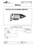
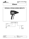
Operation & Service Manual
823090
2/01
136 Bandsaw
136
B
V
L
Series:
136
Tool Type:
B
Bandsaw
Speed:
V
Handle:
Variable
L
Inline (Lock-Off Lever)
NORTH AMERICA
EUROPE
CooperTools
P.O. Box 1410
Lexington, SC 29071
Cooper Power Tools GmbH & Co.
Postfach 30
D-73461 Westhausen
1
Safety Recommendations
For your safety and the safety of others, read and understand the
safety recommendations before operating this saw.
is accidently engaged. Do not use tool to drain residual air from air
line. A self-relieving valve is recommended for this purpose.
Always wear protective equipment.
Work Environment. Work areas should be kept clean and free
from clutter. Visitors should be kept away from work area. The air
hose should be suspended or placed to prevent damage to the
hose or inadvertent tripping to workers. An improperly placed hose
can be hooked by a vehicle or worker pulling the saw out of the
user’s hands or causing a loss of balance. After use the saw should
be disconnected properly and stored.
!
CAUTION
Personal hearing protection is
recommended when operating
or working near this tool.
Caution: Faceshields do not provide unlimited protection against
flying particles and are not to be considered as eye protection. ANSI
Z87.1 states that separate eyewear shall be used. For additional
information on eye protection, refer to Federal OSHA Regulations,
29 CFR, Section 1910.133, Eye and Face Protection, and ANSI
Z87.1, Occupational and Educational Eye and Face Protection. This
standard is available from the American National Standards Institute, Inc., 11 West 42nd Street, New York, NY 10036.
!
CAUTION
Personal hearing protection is
recommended when operating
or working near this tool.
Hearing protection is recommended in high noise areas (above 85
dBA). Close proximity of additional tools, reflective surfaces, process noises, and resonant structures can substantially contribute
to the sound level experienced by the operator. Proper hearing conservation measures, including annual audiograms and training in
the use and fit of hearing protection devices may be necessary. For
additional information on hearing protection, refer to Federal OSHA
Regulations, 29 CFR, Section 1910.95, Occupational Noise Exposure, and American National Standards Institute, ANSI S12.6, Hearing Protectors.
!
WARNING
Wear respirator where
necessary.
Other protective clothing should be worn as required, unless it creates a greater hazard. Do not wear loose fitting clothing or any jewelry. Gloves can be caught in the the rotating blade causing severe
injury. Avoid inhaling dust resulting from the operation of this saw.
Wear approved respirator or mask if ventilation is inadequate. Respirators should be selected, fitted, used and maintained in accordance with Occupational Safety and Health Administration and other
applicable regulations.
This saw is designed to operate on 90 psig (6.2 bar) max. air pressure. Installation of a filter-regulator-lubricator in air supply line is
highly recommended. Before tool is connected to air supply, check
throttle for proper operation, i.e., throttle moves freely and returns
to closed position. Clear air hose of accumulated dust and moisture. Be careful not to endanger adjacent personnel. Before removing tool from service or changing blades, make sure air line is shut
off and drained of air. This will prevent tool from operating if throttle
2
!
WARNING
Electrical and/or explosive hazard. Be
certain that the object being cut does not
contain electrical wires or gases.
Safe Use. Keep both hands on the saw and away from the cutting
area while the blade is rotating. Blades should be kept sharp. Materials to be cut must be securely held to prevent movement. Be aware
that end pieces may fall after being cut, and care must be exercised. Never use liquid coolants or cutting oils on the blade or band
mechanism. Damage may occur to the blade guides and pulley
tires. When cutting conduit or pipe, be certain that live electrical
wires and explosive and/or harmful gases or liquids are not present.
!
WARNING
Repetitive work motions and/or vibration
may cause injury to hands and arms.
Use minimum hand grip force consistent
with proper control and safe operation.
Keep body and hands warm and dry.
Avoid anything that inhibits blood circulation.
Avoid continuous vibration exposure.
Keep wrists straight.
Avoid repeated bending of wrists and hands.
Some individuals may be susceptible to disorders of the hands and
arms when performing tasks consisting of highly repetitive motions
and/or exposure to extended vibration. Cumulative trauma disorders such as carpal tunnel syndrome and tendonitis may be caused
or aggravated by repetitious, forceful exertions of the hands and
arms. Vibration may contribute to a condition called Raynaud’s Syndrome. These disorders develop gradually over periods of weeks,
months, and years. It is presently unknown to what extent
exposureorders develop gradually over periods of weeks, months,
and years. It is presently unknown to what extent exposure to vibrations or repetitive motions may contribute to the disorders. Hereditary factors, vasculatory or circulatory problems, exposure to cold
and dampness, diet, smoking and work practices are thought to
contribute to the conditions.
Tool operators should be aware of the following warning signs and
symptoms so that a problem can be addressed before it becomes a
debilitating injury. Any user suffering prolonged symptoms of tingling, numbness, blanching of fingers, clumsiness or weakened grip,
nocturnal pain in the hand, or any other disorder of the shoulders,
arms, wrists, or fingers is advised to consult a physician. If it is
determined that the symptoms are job related or aggravated by
Safety Recommendations
movements and postures dictated by the job design, it may be necessary for the employer to take steps to prevent further occurrences.
These steps might include, but are not limited to, repositioning the
workpiece or redesigning the workstation, reassigning workers to
other jobs, rotating jobs, changing work pace, and/or changing the
type of tool used so as to minimize stress on the operator. Some
tasks may require more than one type of tool to obtain the optimum
operator/tool/task relationship.
•
Tasks should be performed in such a manner
that the wrists are maintained in a neutral posi
tion, which is not flexed, hyperextended, or
turned side to side
•
Stressful postures should be avoided — select a tool appropriate for the job and work lo
cation
The following suggestions will help reduce or moderate the effects
of repetitive work motions and/or extended vibration exposure:
•
Use a minimum hand grip force consistent with
proper control and safe operation
•
Avoid highly repetitive movements of hands and
wrists, and continuous vibration exposure (after each period of operation, exercise to increase blood circulation)
•
Keep tool well maintained and replace worn
parts (a preventative maintanance program
with scheduled inspections is highly recommended)
204203
204203
!
WARNING
Electrical and/or explosive hazard. Be
certain that the object being cut does not
contain electrical wires or gases.
OVER
Repetitive work motions and/or vibration
can cause injury to hands and arms.
Use minimum hand grip force consistent with
proper control and safe operation.
Keep body and hands warm and dry.
Avoid anything that inhibits blood circulation.
Avoid continuous vibration exposure.
Keep wrists straight.
Avoid repeated bending of wrists and hands.
SAFETY
INSTRUCTIONS
1. Use eye and hearing protection.
2. Keep hands away from cutting
area.
3. Turn off air when not in use, when
changing or adjusting blades, or
servicing.
4. Secure work. Use clamps or vise
to hold work.
5. Stay clear of end pieces that may
fall after being cut off.
6. Keep blades sharp.
CAUTION
Ulnar Deviation
WARNING
Neutral
!
Avoid
WARNING
Radial Deviation
OK
!
Flexion
Avoid
!
Neutral
Avoid
Personal hearing protection is
recommended when operating
or working near this tool.
OK
This information is a compilation of general safety practices obtained from various sources available at the date of production.
However, our company does not represent that every acceptable
safety practice is offered herein, or that abnormal or unusual circumstances may not warrant or require additional procedures. Your
work may require additional specific safety procedures. Follow these
procedures as required by your company. For more information,
see the latest edition of ANSI B186.1, Safety Code for Portable Air
Tools available from the American National Standards Institute, Inc.,
11 West 42nd Street, New York, NY 10036.
Impact resistant eye protection
must be worn while operating
or working near this tool.
Avoid anything that inhibits blood circulation
— Smoking Tobacco (another contribut
ing factor)
— Cold Temperatures
— Certain Drugs
Hearing protection is recommended in high noise
areas (above 85 dBA). Close proximity of other
tools, reflective surfaces, process noises, and
resonant structures can substantially contribute
to the sound level experienced by the user.
•
Read Operating Instructions carefully. Follow
the Safety Recommendations for your safety
and the safety of others.
Extension
Keep body and hands warm and dry (cold
weather is reported to be a major factor contributing to Raynaud’s Syndrome)
Do not remove this tag until
the operator of this tool has
read these safety precautions.
Avoid
•
204204
204204
204737
3
READ SAFETY RECOMMENDATIONS
BEFORE CONNECTING TOOL.
OPERATING INSTRUCTIONS
The Cleco bandsaw is designed to operate on 90 psig (6.2
bar) maximum air pressure, using a 5/16" (8mm) x 8' whip
hose. If additional length is required, the next larger hose
size may be connected to the 8' whip hose.
TO START AND STOP SAW
Connect air supply. Push the lock-off device foward
(A),Fig.1, and depress the throttle lever (B), Fig.1, to start
the saw. Releasing throttle lever will stop saw.
B
A
WHICH BLADE TO USE
In general, select a blade which will allow at least two teeth
to be engaged in the material thickness. The thinner or the
harder the material, the finer the blade teeth. The thicker or
the softer the material, the coarser the blade teeth. Hi-speed
steel blades stay sharp longer than alloy steel blades. Due
to the many materials that can be cut, operator's experience will determine which blade will have the longest life for
any specific operation.
USE OF LUBRICANTS
NEVER USE LIQUID COOLANT WITH YOUR BANDSAW.
Damage to the blade guide bearings or rubber tires on the
pulleys may result.
Bandsaw lube wax is available and recommended when
cutting aluminum, brass and thick materials. Cast iron should
be cut dry.
With the saw running, apply the wax momentarily to both
sides of the blade. Reapply wax intermittently as needed.
!
WARNING
EXERCISE EXTREME CARE TO PREVENT HANDS
FROM CONTACTING THE BLADE.
Fig. 1
LUBRICATION
An automatic in-line filter-lubricator is recommended as it
increases tool life and keeps the tool in sustained operation. The in-line lubricator should be regularly checked and
filled with a good grade of 10W machine oil. Proper
adjustment of the in-line lubricator is performed by placing
a sheet of paper next to the exhaust ports and holding the
throttle open approximately 30 seconds. The lubricator is
properly set when a light stain of oil collects on the paper.
Excessive amounts of oil should be avoided.
STORAGE
In the event that it becomes necessary to store the tool for
an extended period of time (overnight, weekend, etc.), it
should receive a generous amount of lubrication at that
time and again when returned to service. The tool should
be stored in a clean and dry environment.
After prolonged cutting, the wax will cling to the pulleys of
your band saw. This does not affect the operation of the
machine. All that is necessary is to disconnect the machine
from the air supply and wipe the wax from the pulleys.
TO CHANGE SAW BLADES
!
WARNING
DISCONNECT SAW FROM AIR SUPPLY.
TO REMOVE BLADE - Turn handle (A), Fig. 2, clockwise to
release tension on the saw blade. Remove the blade, first
from the pulleys and then from the blade guide.
TYPE OF MATERIALS
The Cleco bandsaw is designed to cut various types of
material up to 4-3/4" diameter or 4-1/4" x 4-3/4" rectangular shape.
SELECTING THE BLADE
The Cleco bandsaw requires blades that are .020 thick,
1/2" wide, and 44-7/8" long. NOTE: Blades for stationary
band saws are of different thickness than above and WILL
NOT fit the precision blade guides on portable band saws.
Therefore, they MUST NOT be used.
4
A
Fig 2.
Before installing a blade, clean chips and wax, which may
have accumulated on blade guides and pulley tires.
6. Repeat Steps 1 through 5 as necessary to achieve proper
tracking.
TO INSTALL BLADE - install blade in blade guides and then
position on pulleys. MAKE SURE TEETH ON LEFT SIDE
OF MACHINE POINT TOWARD THE REAR OF THE MACHINE. See Fig. 3.
DIRECTION OF BLADE TRAVEL
ON LEFT SIDE OF MACHINE
POSITION OF TEETH
ON LEFT SIDE OF MACHINE
Fig. 3
A
Turn handle (A), Fig. 2, counterclockwise as far as it will go.
This reinstates tension on saw blade.
Start and stop saw two or three times to seat blade on pulleys.
TO ADJUST BLADE TRACKING
This Bandsaw is equipped with an adjustable Blade Tracking Mechanism. When properly adjusted, the back edge of
the blade will run lightly against at least one of the back-up
rollers, but will not press heavily against the roller. If the
blade fails to track correctly, adjust as follows:
Fig. 5
HOW TO USE A PORTABLE BANDSAW
1. Verify material to be cut is firmly held to prevent movement.
2. Hold the saw as shown in Fig. 5, with the work stop (A)
contacting the work and blade teeth clear of the work.
1.
!
WARNING
DISCONNECT SAW FROM
POWER SOURCE.
2. Use a 9/|6" wrench to loosen the adjustment locking nut
(see Fig. 4), by turning it counterclockwise, one or two
turns.
3. Turn saw "ON" and lower onto work. Allow weight of saw
to control cutting pressure. Additional pressure will slow
down speed of the blade and reduce cutting efficiency.
4. Hold saw straight in the cut. Any twisting or cocking of
the blade results in shorter blade life.
!
TRACKING SCREW
CAUTION
5. Stay clear of end pieces that may fall after being cut
off.
6. At completion of cut DO NOT allow saw to fall against
work. HOLD SAW SECURELY.
7. Fig. 6 shows the proper cutting position for various shapes.
LOCKING NUT
Fig. 4
3. Use a flat screwdriver to turn the tracking screw 1/4 turn.
Turning the screw clockwise will move the blade further
up, toward the blade guide rollers. Turning the screw
counterclockwise will move the blade down, away from
the blade guide rollers.
RIGHT WAY
WRONG WAY
RIGHT WAY
WRONG WAY
RIGHT WAY
WRONG WAY
4. Tighten the adjustment Iocking nut.
5. Following the directions in TO START AND STOP SAW,
operate the saw and observe blade tracking.
Fig. 6
5
MAINTENANCE
Periodically blow out all air passages with dry compressed
air. Remove wax and chip buildup from pulley tires and blade
guides. All plastic parts should be cleaned with a soft damp
cloth. NEVER use solvents to clean plastic parts. They could
possibly dissolve or otherwise damage the material.
SERVICE AND REPAIRS
All quality tools will eventually require servicing or replacement of parts due to wear from normal use. Repairs should
be made by trained staff familiar with this product or by an
authorized Cleco Service Center. Original factory replacement parts are recommended to maintain factory performance specifications. If you have any questions about this
product, please contact your Cleco distributor or salesman.
DISASSEMBLY
BACKHEAD
The backhead 204212, can be separated from the handle
adapter 204206, by removing the retainer pin 204327. To
gain access to this pin, carefully roll the grip sleeve 204213,
back over itself beginning at the end adjacent to the handle
adapter, and until the pin becomes visible. Note: If "O"-rings
844311 and 847272 (2) two, are replaced, do not lubricate.
For inspection or replacement of the throttle valve or related
parts, unscrew the inlet bushing 204220. The air inlet screen
863598, should be washed in a solvent and blown out in the
reverse of normal air flow. Replace the screen if clogged or
torn.
HANDLE ADAPTER & UPPER HOUSING
The handle adapter and upper housing 204210 should not
be disassembled unless necessary. To disassemble handle
adapter from upper housing remove (3) three hex cap
screws 624820 and pull apart. To remove upper housing
from lower housing, remove (7) seven hex cap screws
204198 and pull apart.
6
LOWER HOUSING & INTERMEDIATE PLATE
To disassemble the lower housing 204211 from the intermediate plate 201655, remove (4) four hex cap screws 845758
and lift complete unit off the intermediate plate. The secondary muffler can be removed for inspection and motor can be
pulled out of lower housing. The primary muffler 204214
inside the lower housing can be removed from inside for
inspection.
MOTOR
Use a suitable driver to drive the front rotor shaft out of the
front rotor bearing. After removing the cylinder and rotor
blades, the rear rotor shaft may be driven out of the rear rotor
bearing.
REASSEMBLY
The tool is reassembled in the reverse order of disassembly.
Wash all parts in a solvent and inspect for damage or wear.
It is recommended that new rotor blades be installed at each
repair cycle. If not replaced, the used ones must measure a
minimum of 3/16" (4.7mm) at both ends.
Replace if 3/16"
(4.7mm) or less
at either end.
Replace bearings that are rough or have excessive end play.
Install the front rotor bearing in the front bearing plate and
measure the distance from the face of the bearing plate to
the inner race of the bearing with the bearing race loaded
rearward. Select or fit by sanding, a rotor collar .001"
(.025mm) to .002" (.050mm) longer than this measurement.
Install the rotor blades, cylinder rear bearing plate, and rear
bearing on the rotor. After final assembly of the motor unit,
the cylinder should be held securely but not tightly between
the two plates. The rotor should not rub either plate.
Tighten all joints securely during reassembly. Place a few
drops of 10W machine oil in the air inlet to ensure positive
lubrication of all motor parts as soon as air is applied.
7
GEAR AND PULLEY HOUSING PARTS LIST
Ref.
No.
Part
No.
7
8*
203096
201652
9*
10
11
11A
12
13
14
15
16
17
18
19
20
21
22
23
23*
201649
204224
204229
204230
204231
204232
204233
204234
204235
204236
204279
204237
204238
204239
204240
204241
201653
24
25
26
27
32
36*
204242
204243
204244
204245
204246
201654
Name of Part
Muffler
Pulley Housing Assembly, T2, Incl. 74,
75,76,83,84
Knob Set
Screw
Tension Lever
Tension Shaft
Yoke
Pulley Tire
Bushing
Bearing
Pulley Shaft
Pulley
Washer
Work Stop
Screw
Blade Guide Roller
Blade Guide Bearing
Blade Guide Holder
Blade Guide Hardware Package Incl. 20,
21,22,24,25,26,27,52
Pin
Washer
Blade Guide Bearing
Screw
Screw
Yoke Kit, Incl. 14
* Subassemblies
8
Ref.
No.
Part
No.
37
38
48
49
52
53
54
55
56
57
58
59
60
61
65
66
74
75
76
80
81
83
84
85
204247
204248
204249
204250
204251
204252
204253
204254
204255
204256
204257
204258
204259
204260
204261
201655
204262
204263
204264
204265
204266
204267
204268
204269
204270
204271
204272
204204
204203
86
87
Name of Part
Screw
Washer
Tension Spring
Screw
Lock Washer
Chain
Driven Sprocket
Screw
Lock Washer
Screw
Washer
Washer
Bearing
Gear & Sprocket
Intermediate Gear
Intermediate Plate Assembly, Incl.60
Needle Bearing
Seal
Bearing
Pin
Washer
Nut,T2
Set-Screw, T2
Retaining Ring, T2
14 Tooth Bi-metal blade
18 Tooth Bi-metal blade
24 Tooth Bi-metal blade
Warning Label
Safety Instruction Label
BANDSAW BACKHEAD &
HOUSING ASSEMBLIES
LOCK-OFF LEVER
BACKHEAD
SUB-ASSEMBLY
201656-6
LOCK-OFF LEVER
SUB-ASSEMBLY
201322-5
202105
203133
869855
845409
204213
203519
204221
847808
204327
844306
204212
204219
844311
203523
203524
204218
203522
844308
864271
204220
863598
203521
624820
847272
842305
204206
844309
844312
204214
204215
204211
204210
619164
204217
TO
INTERMEDIATE
PLATE
204198
204216
845758
INSERT
MOTOR ASSEMBLY HERE
PARTS LIST BANDSAW BACKHEAD & HOUSING ASSEMBLIES
Part No.
202105 †
203133 †
203519
203521
203522
203523
203524
204198 *
204206 *
204210 *
204211 *
204212
204213
204214 *
204215 *
204216 *
204217 *
204218
204219
Name of Part
LOCK-OFF PAWL
LOCK-OFF LEVER
EXHAUST DEFLECTOR
THROTTLE VALVE SPRING
THROTTLE VALVE
THROTTLE VALVE SEAT
THROTTLE VALVE BUSHING
SOCKET CAP SCREW
HANDLE ADAPTER
UPPER HOUSING
LOWER HOUSING
BACKHEAD
GRIP SLEEVE
PRIMARY MUFFLER
SECONDARY MUFFLER
SPACER
WAVY WASHER
THROTTLE VALVE SEAL
FLOW VALVE
3ty.
1
1
1
1
1
1
1
7
1
1
1
1
1
1
1
1
2
1
1
Part No.
204220
204221
204327
619164 *
624820
842305
844306
844308
844309
844311
844312
845409†
845758 *
847272
847808
863598
864271
869855 †
869856 †
Name of Part
INLET BUSHING
THROTTLE PIN
RETAINER PIN
O- RING
CAP SCREW
WASHER, LOCK
O- RING
O- RING
O- RING
O- RING
O- RING
LOCK-OFF LEVER SPRING PIN
ALLEN CAP SCREW
O-RING
LOCK-OFF LEVER PIN
INLET SCREEN
SNAP RING
LOCK-OFF LEVER SPRING
LOCK-OFF LEVER SPRING PIN
Qty.
1
1
1
1
3
3
1
1
1
1
1
1
4
2
1
1
1
1
1
The complete Backhead can be purchased as a subassembly using part number: 201656. *Not included in Backhead subassembly.
The complete Lock-off lever can be purchased as a subassembly using part number: 201322. †Included in Lock-off lever subassembly.
9
BANDSAW MOTOR
204223
869449
847528
812165
204312
869448
204222
ROTOR COLLAR
PART NO.
SIZE
864489
847525
864493
865417
.122"
.124"
.126"
.128"
PARTS LIST BANDSAW MOTOR
* ONLY ONE ROTOR COLLAR
REQUIRED.
10
Part No.
204222
204223
204312
812165
847525
847528
864489
864493
865417
869445
869448
869449
Name of Part
REAR BEARING PLATE
ROTOR
CYLINDER (INCLS. 812165)
CYLINDER PIN
Rotor Collar .124"
Front Rotor Bearing
Rotor Collar .122"
Rotor Collar .126"
Rotor Collar .128"
REAR BEARING
FRONT BEARING PLATE
ROTOR BLADE
Qty.
1
1
1
1
*
1
*
*
*
1
1
4
869445
NOTES
11
CooperTools
670 Industrial Drive
Lexington, SC 29072
Phone: (803) 359-1200
Fax: (803) 359-2013
www.cooperindustries.com
12