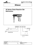
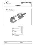
1
Operation & Service Manual
823181
2/01
40 Series Nutrunners
40
X N A
L
- XX XX B
-
X
Series:
Output Drive:
40
2
3
4
Q
M
1/4"
3/8"
1/2"
Quick Change
.25 Magnetic
Nutrunner:
S
Built-in Socket
(Specify Size)
Clutch Designation:
T
Threaded Spindle
Rotation:
Non Reversible
R
A
Reversible
Clecomatic
Handle:
L
Generation:
Lever
Gear Train Designation:
10 30 204
20 104 304
For additional product information visit our website at http://www.clecotools.com
NORTH AMERICA
CooperTools
P.O. Box 1410
Lexington, SC 29071
B
Second
Angle Terminations:
K
M
P
EUROPE
Cooper Power Tools GmbH & Co.
Postfach 30
D-73461 Westhausen
1
Safety Recommendations
For your safety and the safety of others, read and understand the
safety recommendations and operating instructions before operating a nutrunner.
the air hose of accumulated dust and moisture. Before connecting
a tool to the air hose or removing a tool from service or changing
sockets, make sure the air line is shut off and drained of air. This will
prevent the tool from operating if the throttle is accidently engaged.
Always wear protective equipment:
!
!
WARNING
Impact resistant eye protection
must be worn while operating
or working near this tool.
For additional information on eye protection and face protection,
refer to Federal OSHA Regulations, 29 Code of Federal Regulations, Section 1910.133., Eye and Face Protection, and American
National Standards Institute, ANSI Z87.1, Occupational and Educational Eye and Face Protection. Z87.1 is available from the American
National Standards Institute, Inc., 11 West 42nd Street, New York,
NY 10036.
!
CAUTION
CAUTION
When using right angle nutrunners, be sure the throttle is positioned
relative to the angle head so that the throttle will not become wedged
against an adjacent object in the "ON" position due to torque
reaction. The angle head may be repositioned with respect to the
lever to accommodate proper location for task. If tool is to be
reversed, locate throttle lever in a neutral position that will prevent
entrapment. Refer to operating instructions for additional information.
It is essential for safe operation that any operator of a nutrunner use
good balance, sure footing, and proper posture in anticipation of a
torque reaction.
Tools with clutches can stall rather than shut-off if adjusted over
maximum power output of tool, or if there is a drop in air pressure.
Operator must then resist stall torque until throttle is released.
Personal hearing protection is
recommended when operating
or working near this tool.
Hearing protection is recommended in high noise areas 85 dBA or
greater. The operation of other tools and equipment in the area,
reflective surfaces, process noises and resonant structures can
substantially contribute to, and increase the noise level in the area.
Excessive air pressure above 90 PSIG and worn motor components
can also increase sound level emitted by tool. Proper hearing
conservation measures, including annual audiograms and training
in the use and fit of hearing protection devices may be necessary.
For additional information on hearing protection, refer to Federal
Regulations, Section 1910.95, Occupational Noise Exposure, and
American National Standards Institute, ANSI S12.6, Hearing Protectors.
Cleco nutrunners are designed to operate on 90 psig (6.2 bar)
maximum air pressure. If the tool is properly sized and applied,
higher air pressure is unnecessary. Excessive air pressure increases the loads and stresses on the tool parts, sockets, and
fasteners and may result in breakage. Installation of a filter-regulator-lubricator in the air supply line ahead of the tool is recommended.
Before the tool is connected to the air supply, check the throttle for
proper operation (i. e., throttle moves freely and returns to closed
position). Being careful not to endanger adjacent personnel, clear
2
Spindle Rotation
Torque Reaction
Tool balance arms are available to absorb the torque reaction of the
tool while balancing the weight of the tool for improved ergonomic
applications.
Safety Recommendations
!
WARNING
Repetitive work motions and/or vibration
may cause injury to hands and arms.
Use minimum hand grip force consistent
with proper control and safe operation.
Keep body and hands warm and dry.
Avoid anything that inhibits blood circulation.
Avoid continuous vibration exposure.
Keep wrists straight.
Avoid repeated bending of wrists and hands.
Some individuals may be susceptible to disorders of the hands and
arms when performing tasks consisting of highly repetitive motions
and/or exposure to extended vibration. Cumulative trauma disorders
such as carpal tunnel syndrome and tendonitis may be caused or
aggravated by repetitious, forceful exertions of the hands and arms.
Vibration may contribute to a condition called Raynaud's Syndrome.
These disorders develop gradually over periods of weeks, months,
and years. It is presently unknown to what extent exposure to
vibrations or repetitive motions may contribute to the disorders.
Hereditary factors, vasculatory or circulatory problems, exposure to
cold and dampness, diet, smoking and work practices are thought to
contribute to the conditions.
Any tool operator should be aware of the following warning signs and
symptoms so that a problem can be addressed before it becomes a
debilitating injury. Any user suffering prolonged symptoms of tingling, numbness, blanching of fingers, clumsiness or weakened
grip, nocturnal pain in the hand, or any other disorder of the
shoulders, arms, wrists, or fingers is advised to consult a physician.
If it is determined that the symptoms are job related or aggravated
by movements and postures dictated by the job design, it may be
necessary for the employer to take steps to prevent further occurrences. These steps might include, but are not limited to, repositioning the workpiece or redesigning the workstation, reassigning workers to other jobs, rotating jobs, changing work pace, and/or changing
the type of tool used so as to minimize stress on the operator. Some
tasks may require more than one type of tool to obtain the optimum
operator/tool/task relationship.
The following suggestions will help reduce or moderate the effects
of repetitive work motions and/or extended vibration exposure:
• Use a minimum hand grip force consistent with proper
control and safe operation
• Keep body and hands warm and dry (cold weather is
reported to be a major factor contributing to Raynaud's
Syndrome)
• Avoid anything that inhibits blood circulation
—Smoking Tobacco (another contributing
factor)
—Cold Temperatures
—Certain Drugs
Avoid
Extension
OK
Neutral
Avoid
Flexion
Avoid
Radial Deviation
OK
Avoid
Neutral
Ulnar Deviation
• Tasks should be performed in such a manner that the
wrists are maintained in a neutral position, which is not
flexed, hyperextended, or turned side to side.
• Stressful postures should be avoided — select a tool
appropriate for the job and work location
• Avoid highly repetitive movements of hands and wrists, and continuous vibration exposure (after each period of operation, exer
cise to increase blood circulation)
• Keep tool well maintained and replace worn parts
Work gloves with vibration reducing liners and wrist supports are
available from some manufacturers of industrial work gloves. Tool
wraps and grips are also available from a number of different
manufacturers. These gloves, wraps, and wrist supports are designed to reduce and moderate the effects of extended vibration
exposure and repetitive wrist trauma. Since they vary widely in
design, material, thickness, vibration reduction, and wrist support
qualities, it is recommended that the glove, tool wrap, or wrist support
manufacturer be consulted for items designed for your specific
application. WARNING! Proper fit of gloves is important. Improperly fitted gloves may restrict blood flow to the fingers and can
substantially reduce grip strength.
3
Safety Recommendations
203185-4
!
WARNING
Wear respirator where
necessary.
Drilling or other use of this tool may produce hazardous fumes and/
or dust. To avoid adverse health effects, utilize adequate ventilation
and/or a respirator. Read the material safety data sheet of any
cutting fluids or materials involved in the drilling process.
!
CAUTION
• Drill bits are sharp. Handle them carefully to avoid injury.
• The cutting tool maximum speed rating must equal or exceed
the rated speed of the tool.
• Use the appropriate size chuck key to securely tighten a drill bit
in the chuck.
• Use precautions when drilling because of the possibility of the
cutting tool bending or breaking.
• High reaction torque may be experienced by the operator with
any drill at breakthrough.
• Drill bits or accessories not centered properly in the chuck can
cause excessive wobble or vibration.
4
203185
203289
WARNING
!
OVER
Repetitive work motions and/or vibration
can cause injury to hands and arms.
Use minimum hand grip force consistent with
proper control and safe operation.
Keep body and hands warm and dry.
Avoid anything that inhibits blood circulation.
Avoid continuous vibration exposure.
Keep wrists straight.
Avoid repeated bending of wrists and hands.
CAUTION
!
Personal hearing protection is
recommended when operating
or working near this tool.
READ
OPERATING
INSTRUCTIONS
Hearing protection is recommended in high noise
areas (above 85 dBA). Close proximity of other
tools, reflective surfaces, process noises, and
resonant structures can substantially contribute
to the sound level experienced by the user.
Follow good machine shop practices. Rotating shafts and moving
components can entangle and entrap, and can result in serious
injuries. Never wear long hair, loose-fitting clothes, gloves, ties, or
jewelry when working with or near a drill of any type.
WARNING
Warning Labels
The warning labels found on these tools are an essential part of this
product. Labels should not be removed. Labels should be checked
periodically for legibility. Replace warning labels when missing or
when the information can no longer be read. Replacement labels
can be ordered as any spare part.
!
Do not wear loose fitting clothes,
long hair, gloves, ties or jewelry.
This information is a compilation of general safety practices obtained
from various sources available at the date of production. However,
our company does not represent that every acceptable safety
practice is offered herein, or that abnormal or unusual circumstances may not warrant or require additional procedures. Your work
may require additional specific safety procedures. Follow these
procedures as required by your company.
Impact resistant eye protection
must be worn while operating
or working near this tool.
WARNING
Read Operating Instructions carefully. Follow
the Safety Recommendations for your safety
and the safety of others.
!
For more information on the safe use of portable air tools, see the
latest edition of ANSI B186.1, Safety Code for Portable Air Tools,
available from the American National Standards Institute, Inc. 11
West 42nd Street, New York, NY 10036.
Do not remove this tag until
the operator of this tool has
read these safety precautions.
ADDITIONAL SAFETY RECOMMENDATIONS FOR USE OF RIGHT
ANGLE DRILLS
OPERATING AND SERVICE INSTRUCTIONS
FOR YOUR SAFETY AND THE SAFETY OF OTHERS READ AND UNDERSTAND THE SAFETY
RECOMMENDATIONS ON PAGES 2 thru 4 BEFORE OPERATING A NUTRUNNER.
CLECOMATIC MODELS
Tools equipped with the CLECOMATIC clutch are designed to
tighten the fastener to a predetermined torque and shut off
automatically. Releasing the throttle lever will allow the tool to
reset for the next cycle.
OFF
CLUTCH ADJUSTMENT
Shut off air supply to the tool and rotate the adjustment cover, No.
202829, 180° to uncover the adjustment slot in the clutch housing.
Rotate the spindle until the hole in the adjustment nut is visible in
the slot. Use a 1/8" (3mm)
diameter pin to hold the
nut. Use a suitable tool to
turn the spindle in a counterclockwise direction to
increase torque or clockwise to decrease torque.
Return the adjustment
cover to its closed position after every adjustment.
If the clutch is adjusted over the maxi! CAUTION mum power output of the tool, the clutch
will not function and the tool will operate
like a stall-type tool. Also, if the tool is being operated at its upper
torque limits, a drop in air pressure could cause the clutch not to
function due to a loss of motor power and the tool will function like
a stall-type tool. If tool stalls, operator must resist stall torque until
the throttle is released.
Operational check: Grip tool securely and be prepared to counteract stall torque in case clutch is improperly adjusted. THIS IS A
HIGH TORQUE TOOL.
THROTTLE POSITION
"K" & "M" Right Angle Head
Both the "K" & "M" heads are threaded to the gear case. Throttle
positioning is accomplished by using shims between the head and
the gear case as required to properly position the throttle lever with
respect to the head to prevent hand entrapment. (See Torque
Reaction page2). Retighten head with proper wrench to a torque
higher than the torque rating of the tool.
"P" Right Angle Head
The throttle lever may be repositioned to accomodate proper
location for task and to avoid hand entrapment. The "P" head is
splined to the gear case. Repositioning of the angle head is done
by loosening housing lock nut No. 203438 (left hand threads), and
lifting angle head enough to disengage the spline and turning to
position desired. Retighten housing lock nut with proper wrench to
20 ft. lbs.
AIR SUPPLY
For maximum performance, use a 3/8" I.D. air hose no longer than
8' in length. If additional length is required, the next larger hose
should be connected to the 3/8" hose.
Being careful to avoid endangering adjacent personnel or yourself, the air hose should be cleared of accumulated dirt and
moisture, then one (1) teaspoonful of 10W machine oil should be
poured into the tool's air inlet before connecting the hose to the
tool.
LUBRICATION
An automatic in-line filter- regulator- lubricator is recommended
as it increases tool life and keeps the tool in sustained operation.
The in-line lubricator should be regularly checked and filled with a
good grade of 10W machine oil. Proper adjustment of the in-line
lubricator is performed by placing a sheet of paper next to the
exhaust ports and holding the throttle open approximately 30
seconds. The lubricator is properly set when a light stain of oil
collects on the paper. Excessive amounts of oil should be avoided.
Application of the tool should govern how frequently it is greased.
It is recommended that the idler gears and right angle gears
receive a generous amount of NLGI 2-EP grease through the
grease fittings every 40 hours of operation.
STORAGE
In the event that it becomes necessary to store the tool for an
extended period of time (overnight, weekend, etc.), it should
receive a generous amount of lubrication at that time and again
when returned to service. The tool should be stored in a clean and
dry environment.
5
DISASSEMBLY
GENERAL
40RNAL0M, 20M, 20K &30K
Unscrew (left hand threads) and remove the angle head. Unscrew
(left hand threads) and remove the clutch housing and clutch.
Unscrew and remove the gear case assembly. The trip rod should
be removed at this time to prevent its being lost or misplaced. The
motor unit may now be removed from the motor housing. See the
following paragraphs for complete disassembly instructions on
the various sub-assemblies.
40RNAL04P, 204P & 304P
With tool mounted vertically in vise, unscrew housing lock nut No.
203438, lift up and remove the angle head. Unscrew and remove
the second reduction gear train. Unscrew (left hand threads) and
remove the clutch housing and clutch. Note: Do not lose finger
spring spacer No. 203457. Unscrew and remove the gear case
assembly. The trip rod should be removed at this time to prevent
its being lost or misplaced. The motor unit may now be removed
from the motor housing. See the following paragraphs for complete disassembly instructions on the various sub-assemblies.
removed by pressing the threaded end of the spindle through the
gear to remove the driven gear. Remove the housing set screw
No. 867546, and using a punch, drive the pinion gear No. 203440,
and bearings No. 203253 and 202197 out the angle head.
CLUTCH DISASSEMBLY
104P, 204P & 304P Models
Unscrew the adjustment nut No. 202755. This will allow the
adjustment plate No. 202754, thrust bearing No. 847596, thrust
race No. 202753, torque spring, release spring No. 202752,
release sleeve No. 203271, three(3) steel balls No. 842161, ball
retainer No. 203272, and five (5) steel balls No. 844077, to be
removed from the clutch spindle assembly.
Wash the spindle assembly in a solvent and rotate the cam No.
203270, to remove as much grease as possible. Remove the
retainer ring No. 202749, ball plug No. 202748, and twelve (12)
steel balls No. 842161, from the cam. This will allow the trip
plunger No. 202745, reset spring No. 202763, and pin No.
843231, to be removed from the rear of the clutch spindle No.
203456.
RIGHT ANGLE HEAD DISASSEMBLY
"K" Right Angle Head
To disassemble the right angle head, unscrew the spindle bearing
cap. This will permit the removal of the spindle assembly.
The pinion bearing retainer No. 863564, may be removed by
utilizing a 5/8" hex nut and a 5/8" deep socket. Drop the hex nut
over the pinion shaft and engage the hex in the bearing retainer
and unscrew the retainer using the deep socket. Using a suitable
driver, drive the pinion No. 202200, and related bearings out of the
angle head.
"M" Right Angle Head
Using a suitable spanner wrench, unscrew (left hand threads) the
bearing cap No. 864396. Remove the spindle, ball bearing No.
842517, and driven gear by clamping the spindle in a vise and
driving the right angle housing No. 869048, away from the spindle
using a soft-faced mallet. The ball bearing can now be removed by
pressing the larger end of the spindle through the bearing I.D.
Press the smaller end of the spindle through the gear to remove
the driven gear. The pinion bearing retainer No. 863564, may be
removed by utilizing a 5/8" hex nut and a 5/8" deep socket. Engage
the hex in the bearing retainer and unscrew the retainer using the
5/8" deep socket. The pinion and bearings may now be removed
by lightly tapping angle head on a soft surface.
"P" Right Angle Head
Using a suitable wrench, unscrew (left hand threads) the bearing
cap, No. 203250. Remove the square drive spindle No. 203249 or
No. 203439, ball bearing, No. 842517, and driven gear No.
203251, by clamping the square drive in the vise. Drive the right
angle housing, No. 203441, away from the square drive using a
soft-faced mallet. Remove the spindle retainer nut, No. 203248,
with a 1/2" (12.7mm) wrench. The ball bearing can now be
6
10M, 20M, 20K &30K Models
Unscrew the adjustment nut No. 202824. This will allow the
adjustment plate No. 202754, thrust bearing No. 847596, thrust
race No. 202753, torque spring, release spring No. 202752,
release sleeve No. 203271, three (3) steel balls No. 842161, ball
retainer No. 203272, and five (5) steel balls No. 844077, to be
removed from the clutch spindle assembly.
Wash the spindle assembly in a solvent and rotate the cam No.
203270, to remove as much grease as possible. Remove the
retainer ring No. 202749, ball plug No. 202748, and twelve (12)
steel balls No. 842161, from the cam. This will allow the trip
plunger No. 202745, reset spring No. 202763, and pin No.
843231, to be removed from the rear of the clutch spindle No.
202848.
2ND REDUCTION GEAR TRAIN
DISASSEMBLY
104P, 204P & 304P Gear Trains
Remove the spider No. 203747, out the rear of gear case No.
203451. If replacement of idler gears are necessary, the idler gear
pins No. 203750 can be driven out the rear of the spider with a
punch. Idler gear bearings No. 203749, can be pressed out of the
idler gears No. 203748.
1ST REDUCTION GEAR TRAIN
DISASSEMBLY
Single Reduction — 204P, 304P, 20M & 20K
Gear Trains
The spider No. 867872 or No. 869182 should be pressed out the
bearing toward the rear of the gear case No. 867871. Remove the
retainer ring No. 844364, and press the bearing No. 847147, out
the front of the gear case.
DISASSEMBLY — Continued
If replacement of the idler gear pins is necessary, they should be
pressed out the rear of the spider. See Fig. 1 for replacement pin
height.
.240
.255
.240
.255
Front
Front
Rear
Rear
104P & 10M 1st Reduction Spider
Fig. 2 — Double Reduction Spiders
Fig. 1 — Single Reduction Spider
Double Reduction — 104P & 10M Gear Trains
Both spiders should be removed from the rear of gear case No.
867907. Remove the retainer ring No. 844364, and press the
bearing No. 847147, out the front of the gear case.
If replacement of the idler gear pins is necessary, they should be
pressed out the rear of the spider. See Fig. 2 for replacement pin
height.
MOTOR HOUSING DISASSEMBLY
Clamp backhead No. 203473 in vise and unscrew motor housing
No. 203459. Reversing valve ring No. 203466 and pin No. 867922
may be removed at this time. Tapping motor housing on soft
surface should remove reversing valve No. 203465. The shut-off
valve No. 203471 and shut-off valve spring No. 203472 can be
removed from backhead at this time to prevent loss. The throttle
rod guide can be pressed out and replaced if necessary.
BACKHEAD DISASSEMBLY
Unscrew and remove the inlet bushing No. 203478 for inspection
and cleaning of the strainer No. 203480, exhaust deflector No.
203479 and mufflers 203481. Replace any parts if clogged or torn.
The porous bronze deflector can be washed in solvent and
reverse blown with compressed air to clean it. The throttle valve
No. 203475 and throttle valve spring No. 203476 may be removed.
The throttle valve seat No. 203474 can be pressed out and
replaced if necessary.
7
REASSEMBLY
GENERAL
All parts should be washed in a solvent and inspected for
damage or wear. Particular attention should be given to all
bearings, gears, gear pins, and rotor blades as failure of these
parts could cause damage to more expensive parts. Rotor
blades should be replaced at every repair cycle or if they
measure less than 3/16" (4.7mm) on either end.
Must be replaced if less than
3/16" (4.7mm) on either end.
NOTE: Refer to pages 18 and 19 for proper tightening
techniques for all components.
Inspect and replace any "O"-rings or seals that show signs of
wear or deterioration. All gears, gear pins, and open bearings
should receive a generous amount of NLGI 2-EP grease during
reassembly. During reassembly of the clutch, all parts should
receive a thin coating of a mixture of 10W machine oil and NLGI
2-EP grease. Reassembly of all of the various sub-assemblies
is in the reverse order of disassembly; however, the following
paragraphs list some of the more important reassembly procedures.
RIGHT ANGLE HEAD REASSEMBLY
"K" Right Angle Head
Slip pinion needle bearing, No. 869864, (unstamped end first)
on the pinion, No. 202200, and press (press on the bearing's
stamped end) the bearing to a depth of 7/8"(22mm) from the face
of the bearing bore. Install pinion ball bearing, No. 847846 and
bearing retainer, No. 863564, in the head and tighten retainer
securely using the 5/8"(16mm) hex nut and 5/8"(16mm) deep
socket. Using a suitable driver through the hole in the top of the
head, drive the pinion back to make sure it is seated properly in
the head.
"M" Right Angle Head
Assemble the spindle and related components in the head and
securely tighten (left hand threads) the bearing cap No. 864396.
Use bearing spacer No. 869050, to press the pinion needle
bearing No. 863360, (press on the bearing's stamped end) in the
head. Install ball bearing No. 847846, and bearing retainer No.
863564, in the head and tighten retainer securely using the 5/8"
hex nut and 5/8" deep socket. Retighten head to tool with proper
wrench to a torque higher than the torque rating of the tool.
"P" Right Angle Head
Assemble the spindle and related components in the head and
securely tighten (left hand threads) the bearing cap No. 203250.
Press the pinion needle bearing No. 203253, (press on the
bearing's stamped end) into the head along with pinion No.
203440 to a depth of 1.250"(31.75mm). Install ball bearing No.
202197. Retighten housing lock nut with proper wrench to 20 ft.
lbs.
MOTOR REASSEMBLY
Assemble the rear rotor bearing and rear bearing plate (press on
the bearing's inner race) onto the rear rotor shaft until there is
approximately .0015" (.038mm) clearance between the plate
and rotor.
8
.0015" (.038mm)
Clearance
Assemble the rear rotor
bearing and rear bearing
plate (press on the
bearing's inner race) onto
the rear rotor shaft until
there is approximately
.0015" clearance between the plate and rotor.
Assemble the five (5) rotor blades, cylinder, front
bearing plate, and front
rotor bearing (press on
the bearing's inner race)
to the rotor assembly. After final assembly, the cylinder should be held
firmly, but not tightly between the two (2) bearing
plates and the rotor
should turn freely and not
rub either bearing plate.
BACKHEAD REASSEMBLY
During reassembly, all "O"-rings should be lubricated with a good
"O"-ring lubricant.
CLUTCH SPACING — 10, 20 & 30
Assemble the tool completely less clutch assembly and trip rod.
Position the right angle head in relation to the throttle lever. Use
spacers No. 863698, to position head. Break assembly apart at
the clutch housing and gear case (left hand threads) and install the
spacers No. 869434, five (5) spacers No. 869423, and clutch
assembly. Reassemble the tool. Measure gap between the clutch
housing and gear case. Remove the appropriate number of
spacers No. 869423, to allow clutch housing and gear case to
make up tight. NOTE: Spacers are .030" (.76mm) thick. If there is
not a gap, add spacers No. 869423, to achieve one. The total
amount of spacers removed must be equal to or greater than the
gap.
EXAMPLE: Gap is .048" (1.22mm). Remove two (2) .030 (.76mm)
thick spacers — .060 (1.52mm) total.
CLUTCH SPACING — 104, 204 & 304
The "O"-rings No. 844306 (.070" /1.8mm) and No. 813449
(.103" /2.6mm) are used to restrict the movement of the clutch in
the clutch housing. The "O"-ring should be chosen that restricts
the movement, but does not become compressed to tightly.
TRIP ROD SIZING
Install trip rod. Screw clutch housing down until tool begins to start.
Continue to screw the housing down 3/4 to turns. Measure the
gap between the clutch housing and gear case. Cut this amount
off the trip rod.
SAFETY CHECK
After repair or replacement of parts, all tools should be tested to
verify that the Clecomatic automatic shut-off device is functioning
properly.
"K" RIGHT ANGLE HEAD
869034
863698 .008"
865723 .004"
ANGLE HEAD ADAPTER
Stall Tools Only
869864
847846
863564
842366
202198
202266
202200
847853 1/4" SQ. DR.
844014 3/8" SQ. DR.
202987 1/4" SQ. DR.
202986 1/4" SQ. DR.
844016 3/8" SQ. DR.
844013 3/8" SQ. DR.
864964
202196
202199
842980
202201
202268 1/4" SQ. DR. 202317
202267 3/8" SQ. DR.
202197
844305
202303
202310
847411
FLUSH SOCKET SPINDLE
SIZE SPINDLE CONVERSION
PART NO. KIT* PART NO.
10mm 202298
201004
13mm 202299
201005
15mm 202300
201006
1/2"
202301
201007
9/16"
202302
201008
813446
1/4" INTERNAL HEX
MAGNETIC SPINDLE
*Conversion kit contains all parts
needed to convert a "K" right angle
head to flush socket operation.
PARTS LIST — "K" RIGHT ANGLE HEAD
PART NO.
201004
201005
201006
201007
201008
202196
202197
202198
202199
202200
202201
202266
202267
202268
202298
202299
202300
202301
202302
202303
NAME OF PART
10mm Conversion Kit
13mm Conversion Kit
15mm Conversion Kit
1/2" Conversion Kit
9/16" Conversion Kit
Spindle Bearing Cap
Spindle Ball Bearing
Spindle Needle Bearing
Spindle Lock Nut
Pinion (8T)
Driven Gear (12T)
Angle Head (incl. 864964)
3/8" Sq. Dr. Spindle (incl. 844013,
844016, 844014)
1/4" Sq. Dr. Spindle (incl. 202987,
847853, 202986)
10mm Flush Socket Spindle
13mm Flush Socket Spindle
15mm Flush Socket Spindle
1/2" Flush Socket Spindle
9/16" Flush Socket Spindle
Bearing Cap
*Number of spacers required is variable.
**Denotes parts not included in subassemblies listed below.
QTY.
1
1
1
1
1
1
1
1
1
1
1
1
1
1
1
1
1
1
1
1
PART NO.
202310
202317
202986
202987
813446
842366
842980
844013
844014
844016
844305
847411
847846
847853
863564
863698**
864964
865723**
869034**
869864
NAME OF PART
1/4" Hex Magnetic Spindle
Felt Ring
Lock Pin Retiner Plug (1/4")
Socket Lock Pin (1/4")
Collar( incl. 844305)
Plug
3/32" Steel Ball
Lock Pin Retainer Plug (3/8")
Lock Pin Spring (3/8")
Socket Lock Pin (3/8")
1/4" x 3/8" "O"-Ring
11/16" x 13/16" "O" Ring
Pinion Ball Bearing
Lock Pin Spring (1/4")
Pinion Ball Ring Retainer
.008" Spacer
Grease Plug
.004" Spacer
Angle Head Adapter
Pinion Needle Bearing
QTY.
1
1
1
1
1
1
23
1
1
1
1
1
1
1
1
*
1
*
1
1
The complete "K" Right Angle Head can be purchased as a subassembly.
1/4" Square Drive — 861146
3/8" Square Drive — 861147
9
"M" RIGHT ANGLE HEAD
869034
863698
865723
.008"
.004"
847846
863360
863564
869050
ANGLE HEAD ADAPTER
Stall Tools Only
882629
869048
869049
843589
847219
867641
867642
864396
864076
842517
867643
847710
869051
FLUSH SOCKET SPINDLE
SIZE SPINDLE CONVERSION
PART NO. KIT* PART NO.
10mm 202566-6
201102
11mm 202725-8
201214
13mm 202567-4
201103
14mm ----------------------15mm 202568-2
201104
3/8-24 Drill Spindle
202569
842980
*Conversion kit contains all parts
needed to convert a "M" right angle
head to flush socket operation.
PARTS LIST — "M" RIGHT ANGLE HEAD
PART NO.
201102
201103
201104
201214
202566
202567
202568
202569
202725
842517
842980
843589
847219
847710
847846
NAME OF PART
10mm Conversion Kit
13mm Conversion Kit
15mm Conversion Kit
11mm Conversion Kit
10mm Flush Socket Spindle
13mm Flush Socket Spindle
15mm Flush Socket Spindle
Bearing Cap
11mm Flush Socket Spindle
Spindle Ball Bearing
3/32' Steel Ball
Grease Fitting
Lock Pin Spring
"O"-Ring 1/2" x 5/8"
Pinion Ball Bearing
*Number of spacers required is variable.
**Denotes parts not included in subassemblies listed below.
10
QTY.
PART NO.
1
1
1
1
1
1
1
1
1
1
30
1
1
1
1
863360
863564
863698
864076
864396
865723
867641
867642
867643
869034
869048
869049
869050
882629
NAME OF PART
QTY.
Pinion Needle Bearing
Pinion Bearing Retainer
Head Positioning Shim (.008')
Driven Gear
Spindle Bearing Cap
Head Positioning Shim (.004')
Lock Pin Retainer Plug
Socket Lock Pin
3/8" Sq. Dr. Spindle (incl. 847219, 867641,
867642)
Angle Head Adapter
Right Angle Head (incl. 843589)
Pinion
Bearing Spacer
Spindle Needle Bearing
The complete "M" Right Angle Head can be purchased as a subassembly.
3/8" Square Drive Spindle — 861637
1
1
*
1
1
*
1
1
1
1
1
1
1
1
40 SERIES "P"
RIGHT ANGLE
HEAD
202197
203437
203438
203443
864105
867546
203441
203440
844016
844011
203248
203251
203253
844014
844014
3/8" SQ. DR.
1/2" SQ. DR.
203439
842517 203249
3/8" SQ. DR.
1/2" SQ. DR.
X
3/8" SQ. DR.
1/2" SQ. DR.
844013
847272
203250
842980
FLUSH SOCKET SPINDLE
SIZE
SPINDLE CONVERSION
PART NO. KIT* PART NO.
10mm
203766
201512
11mm
203767
201513
13mm
203768
201514
14mm
203769
201515
15mm
203770
201516
15mm
204225
NONE
15mm
204315
NONE
16mm
203962
201569
17mm
203771
201517
9/16"
203807
201528
847445
203772
*Conversion kit contains all
parts needed to convert a
"P" right angle head to flush
socket operation.
PARTS LIST — 40 SERIES "P" RIGHT ANGLE HEAD
PART NO.
201512
201513
201514
201515
201516
201517
201528
201569
203766
203766
203767
203768
203769
203770
203771
203772
203807
203962
202197
203248
203249
203250
NAME OF PART
10mm Conversion Kit
11mm Conversion Kit
13mm Conversion Kit
14mm Conversion Kit
15mm Conversion Kit
17mm Conversion Kit
9/16" Conversion Kit
16mm Conversion Kit
10mm Flush Socket Spindle
10mm Flush Socket Spindle
11mm Flush Socket Spindle
13mm Flush Socket Spindle
14mm Flush Socket Spindle
15mm Flush Socket Spindle
17mm Flush Socket Spindle
Spindle Bearing Cap
9/16" Flush Socket Spindle
16mm Flush Socket Spindle
Pinion Ball Bearing
Spindle Lock Nut
1/2" Sq. Dr. Spindle (incl. 844011, 844014, 844013)
Spindle Bearing Cap
QTY. PART NO.
1
1
1
1
1
1
1
1
1
1
1
1
1
1
1
1
1
1
1
1
1
1
NAME OF PART
QTY.
203251
203253
203437
203438
203439
203440
203441
203443
204225
Driven Gear
Pinion Needle Bearing
Pinion Bearing Retainer
Housing Lock Nut
3/8" Sq. Dr. Spindle (844016, 844014, 844013)
Pinion Gear
Housing
Housing Clamp Ring
15mm Extended Socket Spindle
1
1
1
1
1
1
1
1
X length 19/32(15mm)
1
204315
15mm Extended Socket Spindle
842517
842980
844011
844013
844014
844016
847272
847445
864105
867546
Spindle Ball Bearing
Ball
1/2" Sq. Dr. Socket Lock Pin
Spring Retainer
1/2" & 3/8" Sq. Dr. Spring
3/8" Sq. Dr. Socket Lock Pin
"O"-Ring 5/8" x 3/4"
"O"-Ring 1/16" X 15/16"
Housing Needle Bearing
Housing Set Screw
X length 29/32(23mm)
1
1
32
1
1
1
1
1
1
1
1
The complete right angle head can be purchased as a subassembly using these part numbers:
3/8" sq. dr. — 201417 — 1/2" sq. dr. — 201418
11
40 SERIES
2ND REDUCTION GEAR TRAIN
FOR
104P, 204P & 304P
203748
203749
203749
203750
203747
203453
203451
PARTS LIST
40 SERIES 2ND REDUCTION
GEAR TRAIN FOR 104P, 204P & 304P
PART NO.
203451
203453
203747
203748
203749
203750
NAME OF PART
Gear Case (45T)
Retainer Ring
Spider
Idler Gear (incl. 2 - 203749)
Idler Gear Bearing
Idler Gear Pin
QTY.
1
1
1
3
6
3
The complete 2nd reduction gear train can be purchased as
a subassembly using part number 201521.
12
1ST REDUCTION 104P & 10M GEAR TRAIN
203781
203793
203784
847147
203783
203782
867902
203749
869584
844364
867907
203785
203786
PARTS LIST — 104P & 10M GEAR TRAINS
PART NO.
203749
203781
203782
203783
203784
203785
203786
203793
844364
847147
867902
867907
869584*
NAME OF PART
QTY.
1st Red. Gear Bearing
2nd Red. Gear (incl. 203749)
1st Red. Gear (15T) (incl. 203749)
2nd Red. Gear Pin
2nd Red. Gear Bearing
2nd Red. Spider
1st Red. Spider (incl. 203793)
1st Red. Gear Pin
Retainer Ring
Ball Bearing
Rotor Pinion (15T)
Gear Case
Pinion Spacer
3
3
3
3
3
1
1
3
1
1
1
1
1
*Denotes parts not included in subassembly.
The complete gear case can be purchased as a subassembly
using Part No. 201522.
1ST REDUCTION 20M, 20K, 204P, 30K & 304P GEAR TRAINS
867871
847147
844364
867921
867922
204 & 20 867872
304 & 30 869182
204 & 20 867866
304 & 30 869181
PARTS LIST
20M, 20K, 204P, 30K & 304P GEAR TRAINS
PART NO.
844364
847147
867866
867871
867872
867921
867922
869181
869182
NAME OF PART
Bearing Retainer Ring
Spider Bearing
204 & 20 Idler Gear (18T)
(incl. 867921)
Gear Case
204 & 20 Spider (incl. 867922)
204, 20, 304 & 30 Idler Gear Bearing
Idler Gear Pin
304 & 30 Idler Gear (16T)
(incl. 867921)
304 & 30 Spider (incl. 867922)
QTY.
1
1
3
1
1
3
3
3
1
The complete gear cases can be purchased as a subassembly
using Part No. 204, 20M & 20K - 861573, 30K & 304 - 861680.
13
40 SERIES CLECOMATIC CLUTCH
FOR
104P, 204P & 304P
202749
202748
202763
203456
842161
202745
"O"-RINGS
844306
or
813449
843231
844077
842161
203270
843791
203271
203285
202753
844975
202754
202752
202755
203272
847596
842517
Green - 304P
White - 204P
Yellow - 104P
202829
-104 Only
-304 &-204
202822
203590
869306
203455
OFF
PARTS LIST — 40 SERIES 104P, 204P & 304P CLECOMATIC CLUTCH
PART NO.
NAME OF PART
202745
202748
202749
202752
202753
202754
202755
202763
202822
202829*
203270
203271
203272
203285
Trip Plunger
Ball Plug
Retainer Ring
Release Spring
Thrust Race
Adjustment Plate
Adjustment Nut
Reset Spring
Torque Spring (Green)
Adjustment Cover
Clutch Cam
Release Sleeve (104)
Ball Retainer
Release Sleeve (304 & 204)
QTY. PART NO.
1
1
1
1
1
1
1
1
1
1
1
1
1
1
203455*
203456
203590
813449
842161
842517*
843231
843791
844077
844306
844975*
847596
869306
NAME OF PART
Clutch Housing
Clutch Spindle (15T)
Torque Spring (White)
"O"-ring
3/16" Steel Ball
Ball Bearing
Reset Pin
Retainer Ring
5/16" Steel Ball
"O"-ring
Retainer Ring
Thrust Bearing
Torque Spring (Yellow)
The complete clutch can be purchased as a subassembly using these part numbers: 104P - 201422,
204P - 201441, & 304P - 201423. * Denotes parts not included in subassembly.
14
QTY.
1
1
1
1
15
1
1
1
5
1
1
1
1
40 SERIES
CLECOMATIC CLUTCH
FOR 10M, 20M, 20K & 30K
202749
202748
842161
202848
843231
202745
203270
842161
869434
202763
202754
844077
202753
203271 -10 & -30
203285 -20
203272
869423
202824
202752
847596
869305 10M - Red
203590 20M & 20K - White
202822 30K - Green
202829
202762
OFF
PARTS LIST — 40 SERIES 10M, 20M, 20K & 30K CLECOMATIC CLUTCH
PART NO.
NAME OF PART
202745
202748
202749
202752
202753
202754
202762*
202763
202822
202824
202829*
202848
Trip Plunger
Ball Plug
Retainer Ring
Release Spring
Thrust Race
Adjustment Plate
Clutch Housing
Reset Spring
Torque Spring (Green)
Adjustment Nut
Adjustment Cover
Clutch Spindle
QTY. PART NO.
1
1
1
1
1
1
1
1
1
1
1
1
203270
203271
203272
203285
203590
842161
843231
844077
847596
869305
869423*
869434*
NAME OF PART
Clutch Cam
Release Sleeve (0 & 0)
Ball Retainer
Release Sleeve (0)
Torque Spring (White)
3/16" Steel Ball
Reset Pin
5/16" Steel Ball
Thrust Bearing
Torque Spring (Red)
Steel Spacer (.030"/.035")
Spacer (.090"/.097")
QTY.
1
1
1
1
1
15
1
5
1
1
**
1
The complete clutch can be purchased as a subassembly using these part numbers: 10M - 201387,
20M & 20K - 201442, & 30K - 201388.
* Denotes parts not included in subassembly. ** Number of spacers required is variable.
15
40 SERIES
MOTORS
FOR
10M, 20M, 20K, 30K, 104P, 204P & 304P
869583
10M &104P
203468
20, 204P & 304P & 30K 203469
10M ,104P,
204P & 20
304P & 30K
203464
203635
203461
203462
Rev.
Non.-Rev.
812165
202704
203488
203630
203489
203460
203638
Rev.
Non.-Rev.
PARTS LIST — 40 SERIES 10M, 20M, 20K, 30K, 104P, 204P & 304P MOTORS
PART NO.
202704
203460
203461
203462
203464
203468
203469
16
NAME OF PART
Front Bearing Plate
Cylinder
10M, 104P, 204P & 20 Rotor (6T)
304P & 30K Rotor (9T)
Rear Bearing Plate
10M & 104P Trip Rod
(.062" Dia. x 73/16" Lg.)
204P, 20, 304P & 30K Trip Rod
(.062" Dia. x 7/16" Lg.)
QTY. PART NO.
1
1
1
1
1
1
1
203488
203489
203630
203635
203638
812165
869583
NAME OF PART
QTY.
Rear Bearing
Front Bearing
Rotor Blade
Rear Bering Plate (Non.-Rev.)
Cylinder (Non.-Rev.)
Cylinder Pin
Motor Spacer
1
1
5
1
1
2
1
40 SERIES
MOTOR HOUSING PARTS &
BACKHEAD ASSEMBLY FOR
10M, 20M, 20K, 30K, 104P, 204P & 304P
MOTOR HOUSING PARTS
(Not included in Backhead Assembly)
Reversible Only
867922
203466 Rev.
203634 Non.-Rev.
203465 Rev.
203636 Non-Rev.
203470
Grip Sleeve Only
203794
863454
203457
CLECO
202697
844265
203459 Rev.
203637 Non.-Rev.
863009
203471
BACKHEAD
ASSEMBLY
202410
203557
203477
OPTIONAL
MUFFLING KIT ASSEMBLY
201426
201632
EXISTING PARTS
203479
203472
Grip Sleeve Only
204152
203473
619999
203474
203479
203476
844309
203481
203481
204157
203475
203478
847272
203481
204156
203480
203481
PARTS LIST — 40 SERIES
MOTOR HOUSING & BACKHEAD ASSEMBLY FOR 10M, 20M, 20K, 30K, 104P, 204P &304P
PART NO.
NAME OF PART
202410*
202697
203457
203459
203465
203466
203470
203471
203472
203473
203474*
203475*
203476*
203477*
203478*
Lever Pin
Spring
Finger Spring Spacer
Motor Housing (incl. 202967, 844265 & 203794)
Reversing Valve
Reversing Valve Ring
Trip Rod Guide
Shut-off Valve
Shut-off Valve Spring
Backhead (incl. 203474)
Throttle Valve Seat
Throttle Valve
Throttle Valve Spring
Throttle Valve Pin
Inlet Bushing
QTY.
1
1
1
1
1
1
1
1
1
1
1
1
1
1
1
PART NO.
NAME OF PART
203479*
203480*
203481*
203557*
203634
203636
203637
203794
204152
619999*
844265
844309
847272*
863009
863454
Exhaust Deflector
Strainer
Muffler
Throttle Lever
Dummy Ring
Valve Block
Motor Housing (Non.-Rev.) (incl. 203794)
Grip Sleeve
Grip Sleeve
Retainer Ring
Ball
"O"-Ring 7/16" x 5/8"
"O"-Ring 5/8" x 3/4"
"O"-Ring 3/4" x 7/8" (Non-Rev. Qty.1)
"O"-Ring 9/16" x 11/16"
QTY.
1
1
2
1
1
1
1
1
1
1
1
1
1
2
1
The complete backhead assembly can be purchased as a subassembly using these part number: 201426.
* Parts included in backhead assembly.
17
Tool Components Tightening Techniques
for
40 Series Right Angle Nutrunners
10, 20 & 30 Gear Trains
1.
Clamp angle head with bushing in vise. Tighten all other components before posi
tioning angle head relationship to throttle lever.
2.
Place spanner wrench in adjustment slot of clutch housing and tighten clutch housing to angle head to 40ft. lbs. (54Nm).
3.
Tighten gear case to clutch housing to 40ft. lbs. (54Nm).
4.
Tighten motor housing to gear case to 40ft. lbs. (54Nm) while holding gear case with
other wrench.
5.
Tighten backhead to motor housing securely.
6.
Tool is equipped with the "M" or "K" head. All components must be tightened. Then
the angle head must be loosened and shimmed for alignment.
Left Hand
Threads
Left Hand
Threads
Use wrench to tighten
motor housing to gear
case while still holding
gear case with other wrench
40 ft. lbs. (54Nm)
Vise Jaws
3
CLUTCH
HOUSING
GEAR
CASE
4
BACKHEAD
MOTOR
HOUSING
1
5
Bushing
Right Hand Threads
Vise Jaws
Place Spanner Wrench in
adjustment slot of clutch 2
housing and tighten to angle
head 40 ft. lbs. (54Nm)
Extension
for
leverage
if needed
Spanner Wrench
Bushing
18
Right Hand
Threads
Use wrench
to tighten
gear case to clutch
housing 40 ft. lbs. (54Nm)
Use wrench to tighten
backhead to motor
housing 40 ft. lbs. (54Nm)
(2) Adjustable Wrench
Tool Components Tightening Techniques
for
40 Series Right Angle Nutrunners
104, 204 & 304 Gear Trains
1.
Clamp angle head with bushing in vise. Tighten all other components before positioning and tightening housing lock nut on angle head.
2.
Place spanner wrench in adjustment slot of clutch housing and tighten clutch housing to second reduction gear case to 40ft. lbs. (54Nm).
3.
Tighten first reduction gear case to clutch housing to 40ft. lbs. (54Nm).
4.
Tighten motor housing to first reduction gear case to 40ft. lbs. (54Nm) while holding
first reduction gear case with another wrench.
5.
Tighten backhead to motor housing securely.
6.
The "P" angle head has a spline for positioning the head to the throttle lever. Once
alignment is achieved, the housing lock nut should be torqued to 20 ft. lbs.
Extension for leverage
if needed
Place Spanner Wrench in
adjustment slot of clutch
housing and tighten to
second reduction
gear case 40 ft. lbs. (54Nm)
Vise Jaws
Left Hand
Threads
Left Hand
Threads
4
2
GEAR
CASE
Use wrench to tighten
motor housing to gear
case while still holding
gear case with other wrench
40 ft. lbs. (54Nm)
GEAR
CASE
CLUTCH
HOUSING
BACKHEAD
MOTOR
HOUSING
5
1
Right Hand
Threads
Bushing
Right Hand Threads
Right Hand
Threads
Use wrench
to tighten
3 gear case to clutch
housing 40 ft. lbs. (54Nm)
While holding clutch housing
with spanner wrench
Vise Jaws
Use wrench to tighten
backhead to motor
housing to
40 ft. lbs. (54Nm)
Extension for leverage
if needed
Spanner Wrench
(2) Adjustable Wrench
Bushing
19
CooperTools
670 Industrial Drive
Lexington, SC 29072
Phone: (803) 359-1200
Fax: (803) 359-2013
www.clecotools.com
20