1
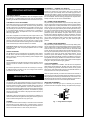
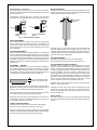
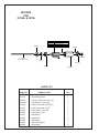
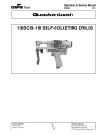
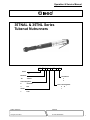
Operation & Service Manual
823091
2/01
35TNAL & 35TNL Series
Tubenut Nutrunners
35
TN A
L
-
XX
-
X
Series:
35
Nutrunner:
TN
Terminations:
Tubenut
6
9
Clutch Designation:
A
-----
Clecomatic
Gear Train Designation:
5 10
7
Stall
Handle:
L
Lever
NORTH AMERICA
EUROPE
P.O. Box 1410
Lexington, SC 29071
Postfach 30
D-73461 Westhausen
1
Safety Recommendations
For your safety and the safety of others, read and understand the
safety recommendations and operating instructions before operating a nutrunner.
may be repositioned with respect to the lever to accommodate
proper location for task. If tool is to be reversed, locate throttle lever
in a neutral position that will prevent entrapment. Refer to operating
instructions for additional information.
Always wear protective equipment:
!
WARNING
Impact resistant eye protection
must be worn while operating
or working near this tool.
For additional information on eye protection and face protection,
refer to Federal OSHA Regulations, 29 Code of Federal Regulations, Section 1910.133., Eye and Face Protection, and American
National Standards Institute, ANSI Z87.1, Occupational and Educational Eye and Face Protection. Z87.1 is available from the American
National Standards Institute, Inc., 11 West 42nd Street, New York,
NY 10036.
!
CAUTION
It is essential for safe operation that any operator of a nutrunner use
good balance, sure footing, and proper posture in anticipation of a
torque reaction.
Tools with clutches can stall rather than shut-off if adjusted over
maximum power output of tool, or if there is a drop in air pressure.
Operator must then resist stall torque until throttle is released.
Spindle Rotation
Tool balance arms are available to absorb the torque reaction of the
tool while balancing the weight of the tool for improved ergonomic
applications.
!
Personal hearing protection is
recommended when operating
or working near this tool.
Hearing protection is recommended in high noise areas 85 dBA or
greater. The operation of other tools and equipment in the area,
reflective surfaces, process noises and resonant structures can
substantially contribute to, and increase the noise level in the area.
Excessive air pressure above 90 PSIG or worn motor components
can also increase sound level emitted by tool. Proper hearing
conservation measures, including annual audiograms and training
in the use and fit of hearing protection devices may be necessary.
For additional information on hearing protection, refer to Federal
Regulations, Section 1910.95, Occupational Noise Exposure, and
American National Standards Institute, ANSI S12.6, Hearing Protectors.
Cleco nutrunners are designed to operate on 90 psig (6.2 bar)
maximum air pressure. If the tool is properly sized and applied,
higher air pressure is unnecessary. Excessive air pressure increases the loads and stresses on the tool parts, sockets, and
fasteners and may result in breakage. Installation of a filter-regulator-lubricator in the air supply line ahead of the tool is recommended.
Before the tool is connected to the air supply, check the throttle for
proper operation (i. e., throttle moves freely and returns to closed
position). Being careful not to endanger adjacent personnel, clear
the air hose of accumulated dust and moisture. Before connecting
a tool to the air hose or removing a tool from service, make sure the
air line is shut off and drained of air. This will prevent the tool from
operating if the throttle is accidently engaged.
!
CAUTION
When using nutrunners, be sure the throttle is positioned relative to
the head so that the throttle will not become wedged against an
adjacent object in the "ON" position due to torque reaction. The head
2
Torque Reaction
WARNING
Pinch Hazard. To avoid
injury to fingers, Keep
hands away from
wrench opening.
204208-3
Keep hands away from wrench opening to avoid injury to fingers.
Some individuals may be susceptible to disorders of the hands and
arms when performing tasks consisting of highly repetitive motions
and/or exposure to extended vibration. Cumulative trauma disorders
such as carpal tunnel syndrome and tendonitis may be caused or
aggravated by repetitious, forceful exertions of the hands and arms.
Vibration may contribute to a condition called Raynaud's Syndrome.
These disorders develop gradually over periods of weeks, months,
and years. It is presently unknown to what extent exposure to
vibrations or repetitive motions may contribute to the disorders.
Hereditary factors, vasculatory or circulatory problems, exposure to
cold and dampness, diet, smoking and work practices are thought to
contribute to the conditions.
Any tool operator should be aware of the following warning signs and
symptoms so that a problem can be addressed before it becomes a
debilitating injury. Any user
suffering proRepetitive work motions and/or vibration
longed sympmay cause injury to hands and arms.
toms of tingling,
Use minimum hand grip force consistent
with proper control and safe operation.
numbness,
Keep body and hands warm and dry.
blanching of finAvoid anything that inhibits blood circulation.
gers, clumsiness
Avoid continuous vibration exposure.
or weakened
Keep wrists straight.
grip, nocturnal
Avoid repeated bending of wrists and hands.
pain in the hand,
or any other disorder of the shoulders, arms, wrists, or fingers is
advised to consult a physician. If it is determined that the symptoms
are job related or aggravated by movements and postures dictated
by the job design, it may be necessary for the employer to take steps
!
WARNING
Safety Recommendations
WARNING
!
203185-4
203185
OVER
Repetitive work motions and/or vibration
can cause injury to hands and arms.
Use minimum hand grip force consistent with
proper control and safe operation.
Keep body and hands warm and dry.
Avoid anything that inhibits blood circulation.
Avoid continuous vibration exposure.
Keep wrists straight.
Avoid repeated bending of wrists and hands.
Avoid
OK
CAUTION
Avoid
!
Avoid
Personal hearing protection is
recommended when operating
or working near this tool.
OK
Hearing protection is recommended in high noise
areas (above 85 dBA). Close proximity of other
tools, reflective surfaces, process noises, and
resonant structures can substantially contribute
to the sound level experienced by the user.
Avoid
READ
OPERATING
INSTRUCTIONS
WARNING
• Avoid anything that inhibits blood circulation
—Smoking Tobacco (another contributing
factor)
—Cold Temperatures
—Certain Drugs
Warning Labels
The warning labels found on these tools are an essential part of this
product. Labels should not be removed. Labels should be checked
periodically for legibility. Replace warning labels when missing or
when the information can no longer be read. Replacement labels
can be ordered as any spare part.
!
• Keep body and hands warm and dry (cold weather is reported to
be a major factor contributing to Raynaud's Syndrome)
Impact resistant eye protection
must be worn while operating
or working near this tool.
• Use a minimum hand grip force consistent with proper control and
safe operation
This information is a compilation of general safety practices obtained
from various sources available at the date of production. However,
our company does not represent that every acceptable safety
practice is offered herein, or that abnormal or unusual circumstances may not warrant or require additional procedures. Your work
may require additional specific safety procedures. Follow these
procedures as required by your company.
Read Operating Instructions carefully. Follow
the Safety Recommendations for your safety
and the safety of others.
The following suggestions will help reduce or moderate the effects
of repetitive work motions and/or extended vibration exposure:
For more information on the safe use of portable air tools, see the
latest edition of ANSI B186.1, Safety Code for Portable Air Tools,
available from the American National Standards Institute, Inc. 11
West 42nd Street, New York, NY 10036.
Do not remove this tag until
the operator of this tool has
read these safety precautions.
to prevent further occurrences. These steps might include, but are
not limited to, repositioning the workpiece or redesigning the workstation, reassigning workers to other jobs, rotating jobs, changing
work pace, and/or changing the type of tool used so as to minimize
stress on the operator. Some tasks may require more than one type
of tool to obtain the optimum operator/tool/task relationship.
203289
Extension
Neutral
Flexion
Radial Deviation
Neutral
Ulnar Deviation
!
• Tasks should be performed in such a manner that the
wrists are maintained in a neutral position, which is not flexed,
hyperextended, or turned side to side.
204208-3
• Stressful postures should be avoided — select a tool
WARNING
Pinch Hazard. To avoid
injury to fingers, Keep
hands away from
wrench opening.
204208
• Avoid highly repetitive movements of hands and wrists, and continuous vibration exposure (after each period of operation, exercise
to increase blood circulation)
• Keep tool well maintained and replace worn parts
Work gloves with vibration reducing liners and wrist supports are
available from some manufacturers of industrial work gloves. Tool
wraps and grips are also available from a number of different
manufacturers. These gloves, wraps, and wrist supports are designed to reduce and moderate the effects of extended vibration
exposure and repetitive wrist trauma. Since they vary widely in
design, material, thickness, vibration reduction, and wrist support
qualities, it is recommended that the glove, tool wrap, or wrist support
manufacturer be consulted for items designed for your specific
application. WARNING! Proper fit of gloves is important. Improperly fitted gloves may restrict blood flow to the fingers and can
substantially reduce grip strength.
3
OPERATING INSTRUCTIONS
CLECOMATIC MODELS
Tools equipped with the CLECOMATIC clutch are designed to tighten
the fastener to a predetermined torque and shut off automatically.
Releasing the throttle lever will allow the tool to reset for the next cycle.
CLECOMATIC CLUTCH ADJUSTMENT
Shut off air supply to the tool and rotate the adjustment cover 202829,
180° to uncover the adjustment slot in the clutch housing. Rotate the
spindle until the hole in the adjustment nut is visible in the slot. Use a
1/8" diameter pin to hold the nut. Use a suitable tool to turn the spindle
in a counterclockwise direction to increase torque or clockwise to
decrease torque. Return the adjustment cover to its closed position
after every adjustment.
If the clutch is adjusted over the maximum power output of the tool, the
clutch will not function and the tool will operate like a stall-type tool. Also,
if the tool is being operated at its upper torque limits, a drop in air
pressure could cause the clutch not to function due to a loss of motor
power and the tool will function like a stall-type tool. If tool stalls operator
must resist stall torque until the throttle lever is released.
Operational check: Grip tool securely and be prepared to counteract
stall torque in case clutch is improperly adjusted. THIS IS A HIGH
TORQUE TOOL.
THROTTLE POSITION
The throttle lever may be repositioned to accomodate proper location
for task and to avoid hand entrapment. Repositioning of the head is
done by adding or removing head positioning shims. Retighten head
with proper wrench.
AIR SUPPLY
The tool is designed to operate at 90 psig (6.2 bar) air pressure. The air
pressure should be checked at the tool's air inlet while the tool is
running.
For maximum performance, use a 5/16" I.D. air hose up to 8' in length.
If additional length is required, a 3/8" I.D. or larger hose should be
connected to the 5/16" I.D. hose.
SERVICE INSTRUCTIONS
LUBRICATION
An automatic in-line filter-regulator-lubricator is recommended as it
increases tool life and keeps the tool in sustained operation. The in-line
lubricator should be regularly checked and filled with a good grade of
10W machine oil. Proper adjustment of the in-line lubricator is performed by placing a sheet of paper next to the exhaust ports and holding
the throttle open approximately 30 seconds. The lubricator is properly
set when a light stain of oil collects on the paper. Excessive amounts of
oil should be avoided.
Application of the tool should govern how frequently it is greased. It is
recommended that the idler gears and head gears receive a generous
amount of NLGI 2-EP grease at every repair cycle.
STORAGE
In the event that it becomes necessary to store the tool for an extended
period of time (overnight, weekend, etc.), it should receive a generous
amount of lubrication at that time and again when returned to service.
The tool should be stored in a clean and dry environment.
4
DISASSEMBLY — GENERAL (ALL MODELS)
Unscrew (left hand threads) and remove the head. Unscrew (left hand
threads) and remove the clutch housing and clutch. Unscrew and
remove the gear case assembly. Note: On models equipped with an
automatic shut-off device, the trip rod should be removed at this time to
prevent its being lost or misplaced. The motor unit may now be removed
from the backhead. See the following paragraphs for complete disassembly instructions on the various subassemblies.
NO. 6 TUBENUT HEAD DISASSEMBLY
The pinion bearing retainer 863564, may be removed by utilizing a 5/8"
hex nut. Engage the nut in the bearing retainer and unscrew the retainer
using a deep socket. The base plate 204291 can be removed using a
3/32" hex wrench to unscrew four 204317 and two 204316 flat head
screws. All gears and gear shafts slip fit in the base plate and housing,
but it may be required to tap shafts out with a punch. All bearings must
be pressed out of gears. The driven gear bearing 842517, can be
pressed off pinion shaft 204298, and pinion shaft can be pressed
through pinion shaft gear 204305, and driven gear 864819 .The pawl
can be removed and pawl alignment pin 842481 can be driven out with
punch. When reassembling head a generous amount of NLGI 2-EP
grease should be applied to all gears. The pawl should be lightly
greased.
NO. 9 TUBENUT HEAD DISASSEMBLY
The pinion bearing retainer 863564, may be removed by utilizing a 5/8"
hex nut. Engage the nut in the bearing retainer and unscrew the retainer
using a deep socket. The base plate 204650 can be removed using a
3/32" hex wrench to unscrew four 204317 and two 204316 flat head
screws. All gears and gear shafts slip fit in the base plate and housing,
but it may be required to tap shafts out with a punch. All bearings must
be pressed out of gears. The driven gear bearing 842517, can be
pressed off pinion shaft 204298, and pinion shaft can be pressed
through pinion shaft gear 204305, and driven gear 864819 .The stop pin
spring 204621 and stop pin 204639 can be removed. When reassembling head a generous amount of NLGI 2-EP grease should be applied
to all gears. The pawl should be lightly greased.
CLUTCH DISASSEMBLY
Unscrew the adjustment nut 202824. This will allow the adjustment
plate 202754, thrust bearing No. 847596, thrust race 202753, torque
spring, release spring 202752, release sleeve 203271, three (3) steel
balls 842161, ball retainer 203272, and five (5) steel balls 844077, to
be removed from the clutch spindle assembly.
Wash the spindle assembly in a solvent and rotate the cam 203270, to
remove as much grease as possible. Remove the retainer ring 202749,
ball plug 202748, and twelve (12) steel balls 842161, from the cam. This
will allow the trip plunger 202745, reset spring 202763, and pin 843231,
to be removed from the rear of the clutch spindle 202848.
GEAR CASE DISASSEMBLY
If replacement of the idler gear pins is necessary, they should be
pressed out the rear of the spider. See Fig. 1 for replacement pin height.
.240
.255
Front
Rear
Fig. 1 — Single Reduction Spider
Double Reduction — Gear Train
Both spiders should be removed from the rear of gear case 867907.
Remove the retainer ring 844364, and press the bearing 847147, out the
front of the gear case.
If replacement of the idler gear pins is necessary, they should be
pressed out the rear of the spider. See Fig. 2 for replacement pin height.
.240
.360
.255
.375
Front
Rear
Front
MOTOR REASSEMBLY
Assemble the rear rotor bearing and rear bearing plate (press on the
bearing's inner race) onto the rear rotor shaft until there is approximately
.0015" clearance between the plate and rotor.
.0015" (.038mm)
Clearance
Rear
10 2nd Reduction
5, 7, 10 1st Reduction
Spider
Spider
Fig. 2 — Double Reduction Spiders
MOTOR DISASSEMBLY
Use a soft-faced hammer to drive the rotor out of the front rotor bearing
619377. This will allow the cylinder and five (5) rotor blades to be
removed from the rotor. Set the rear bearing plate on the vise jaws with
the rotor hanging down. Use a 7/32" punch to drive the rotor out of the
rear rotor bearing.
BACKHEAD DISASSEMBLY
Unscrew and remove the inlet bushing 867882, for inspection and
cleaning of the air inlet screen 833300. Replace the screen if clogged
or torn. The throttle valve and related components may be removed by
unscrewing the throttle valve cap 832207. The reversing valve 204172,
and related components may be removed by unscrewing the second
throttle valve cap 832207, and driving the pin 864734, in the side of the
backhead out.
REASSEMBLY — GENERAL
All parts should be washed in a solvent and inspected for damage or
wear. Particular attention should be given to all bearings, gears, gear
pins, and rotor blades as failure of these parts could cause damage to
more expensive parts. Rotor blades should be replaced every time tool
is repaired or if they measure less than 3/16" on either end.
Must be replaced if less than
3/16" (4.7mm) on either end.
Assemble the five (5) rotor blades, cylinder, front bearing plate, and
front rotor bearing (press on the bearing's inner race) to the rotor
assembly. After final assembly, the cylinder should be held firmly, but
not tightly between the two (2) bearing plates and the rotor should turn
freely and not rub either bearing plate.
BACKHEAD ASSEMBLY
Assemble the backhead in reverse order of disassembly.
Note: Throttle valve bushing is held in by #609 locktite only.
TRIP ROD SIZING (CLECOMATIC MODELS)
Assemble the tool completely less clutch assembly and trip rod.
Position the right angle head in relation to the throttle lever. Use spacers
863698, to position head. Break assembly apart at the clutch housing
and gear case (left hand threads) and install the spacers 869434, five
(5) spacers 869423, and clutch assembly. Reassemble the tool.
Measure gap between the clutch housing and gear case. Remove the
appropriate number of spacers 869423, to allow clutch housing and
gear case to make up tight. NOTE: Spacers are .030" (.76mm) thick. If
there is not a gap, add spacers No. 869423, to achieve one. The total
amount of spacers removed must be greater than the gap.
EXAMPLE: Gap is .048" (1.22mm). Remove two (2) .030 (.76mm) thick
spacers — .060 (1.52mm) total.
Inspect and replace any "O"-rings or seals that show signs of wear or
deterioration. All gears, gear pins, and open bearings should receive a
generous amount of NLGI 2-EP grease during reassembly.
During reassembly of the clutch, all parts should receive a thin coating
of a mixture of 10W machine oil and NLGI 2-EP grease.
Reassembly of all of the various sub-assemblies is in the reverse order
of disassembly; however, the following paragraphs list some of the
more important reassembly procedures.
Install trip rod. Screw clutch housing down until tool begins to start,
continue to screw the housing down after tool starts one revolution.
Measure the gap between the clutch housing and gear case. Cut this
amount off the trip rod.
SAFETY CHECK
After repair or replacement of parts, tools equipped with an automatic
shut-off device should be tested to verify that the device is functioning
properly.
TUBENUT HEAD REASSEMBLY
Assemble the tubenut head in the reverse order of disassembly.
Note: Pinion gear needle bearing is a slip fit on pinion gear.
Alignment of output gear is achieved by rotating the cam gear 204292
or 204641, until it stops against pawl 204296 or slot in cam gear 204641,
then align opening in output gear with opening in housing.
5
NO. 6 - 35TNAL & TNL
TUBENUT HEAD
843827
204291
869034
204304
812625
842481
ANGLE HEAD ADAPTER
Stall Tools Only
204296
204302
204303
Drive Shaft Subassembly
201661
204293
204294
612229
OUTPUT GEAR
PART NO.
204319
204320
204321
204297
204306
204308
204309
204310
204311
IN
5/16
MM
8
9
204301
10
11
12
7/16
204301
204295
1/2
13
864819
204784
204295
382253
3/8
204305
847734
382253
865192
204298
204791
Cam Gear Subassembly
201849
863698
865723
EXTENDED OUTPUT GEAR
PART NO.
204373
204374
204375
204376
204377
204378
204379
204380
204381
IN
5/16
.008"
.004"
847846
MM
842517
204300
8
9
863360
863564
3/8
7/16
10
11
12
204316
1/2
204207
13
204317
All extended sockets extend
3/8" from base plate of head.
PARTS LIST
PART NO.
204207
204291
204293
204294
204295
204296
204298Ð
204299
204300
204301
204302
204303
204304
204305Ð
204316
NAME OF PART
Housing
Base Plate
Idler Gear (20T)
Step Over Gear
Idler Gear (16T)
Pawl (includes 842481)
Pinion Shaft
Cam Gear Shaft
Pinion Gear
Idler Gear Shaft
Idler Gear Shaft
Step Over Gear Shaft
Pawl Spring
Pinion Shaft Gear
Flat Head Screw (Short)
*Number of spacers required is variable.
†Denotes parts not included in subassemblies listed below.
Driven gear subassembly may be purchased using part no.
201661 (Ð parts included 204298, 204305 & 864819).
6
QTY.
1
1
1
1
2
1
1
1
1
2
1
1
1
1
2
PART NO.
204317
204791
382253
612229
812625
842481
842517
843827
847734
847846
863360
863564
863698†
864819Ð
865723†
869034†
NAME OF PART
Flat Head Screw (Long)
Cam Gear (20T)
Cam Gear Bearing & Idler Gear Bearing
Idler Gear Bearing
Pawl Spring Retainer Pin
Pawl Alignment Pin (included in 204296)
Driven Gear Ball Bearing
Driven Gear Needle Bearing
Step Over Gear Bearing
Pinion Ball Bearing
Pinion Needle Bearing
Pinion Bearing Retainer
Head Positioning Shim (.008")
Driven Gear
Head Positioning Shim (.004")
Head Adapter (Stall Tools Only)
The complete No. 6 tubenut head and output gear (output gear size
must be specified using chart above) can be purchased as a
subassembly using Part No. 201663.
QTY.
4
1
3
1
1
1
1
1
1
1
1
1
*
1
*
1
NO. 9 - 35TNAL & TNL
TUBENUT HEAD
843827
204650
869034
ANGLE HEAD ADAPTER
Stall Tools Only
204302
204303
Drive Shaft Subassembly
201661
204293
612229
204294
204305
847734
204639
204301
OUTPUT GEAR
PART NO.
204654
204716
204717
204649
204640
IN
9/16
5/8
204621
204295
MM
13
14
15
382253
204301
204651
864819
204641
204298
865192
884125
863698
865723
204295
16
382253
EXTENDED OUTPUT GEAR
PART NO.
IN
MM
204655
13
204718
14
204719
15
204656
9/16
204657
5/8
16
All extended sockets extend
3/8" from base plate of head.
.008"
.004"
847846
842517
204300
863360
863564
204316
204648
204317
PARTS LIST
PART NO.
204293
204294
204295
204298Ð
204299
204300
204301
204302
204303
204305Ð
204316
204317
204621
204639
204641
204648
NAME OF PART
Idler Gear (20T)
Step Over Gear
Idler Gear (16T)
Pinion Shaft
Cam Gear Shaft
Pinion Gear
Idler Gear Shaft
Idler Gear Shaft
Step Over Gear Shaft
Pinion Shaft Gear
Flat Head Screw (Short)
Flat Head Screw (Long)
Stop Pin Spring
Stop Pin
Cam Gear (24T)
Housing
*Number of spacers required is variable.
†Denotes parts not included in subassemblies listed below.
Driven gear subassembly may be purchased using part no.
201661 (Ð parts included 204298, 204305 & 864819).
QTY.
1
1
2
1
1
1
2
1
1
1
2
4
1
1
1
1
PART NO.
204650
204651
382253
612229
842517
843827
847734
847846
863360
863564
863698†
864819Ð
865192
865723†
869034†
884125
NAME OF PART
Base Plate
Cam Gear Shaft
Idler Gear Bearing
Idler Gear Bearing
Driven Gear Ball Bearing
Driven Gear Needle Bearing
Step Over Gear Bearing
Pinion Ball Bearing
Pinion Needle Bearing
Pinion Bearing Retainer
Head Positioning Shim (.008")
Driven Gear
Cam Gear Needle Bearing
Head Positioning Shim (.004")
Head Adapter (Stall Tools Only)
Alignment Pin (included in housing)
QTY.
1
1
2
1
1
1
1
1
1
1
*
1
1
*
1
4
The complete No. 9 tubenut head and output gear (output gear size
must be specified using chart above) can be purchased as a
subassembly using Part No. 201773.
7
35 CLECOMATIC CLUTCH
202749
202763
202748
202848
842161
843231
202745
842161
869423 .035/.030
869434 .097/.090
202824
847596
202754
202829
202745
202748
202749
202752
202753
202754
202762*
202763
202822
202824
202829
202848
203270
203271
203272
842161
843231
844077
847596
869305
869306
869423*
869434*
8
203271
202753
202762
PART NO.
203270
844077
202752
203272
869305 - 5 Red
869306 - 7 & - 10 Yellow
NAME OF PART
Trip Plunger
Ball Plug
Retainer Ring
Release Spring
Thrust Race
Adjustment Plate
Clutch Housing
Reset Spring
Torque Spring (Green)
Adjustment Nut
Adjustment Cover
Clutch Spindle
Clutch Cam
Release Sleeve
Ball Retainer
3/16" Steel Ball
Reset Pin
5/16" Steel Ball
Thrust Bearing
Torque Spring (Red)
Torque Spring (Yellow)
Steel Spacer (.030"/.035")
Spacer (.090"/.097")
QTY.
1
1
1
1
1
1
1
1
1
1
1
1
1
1
1
15
1
5
1
1
1
**
1
* Denotes parts not included in
subassembly.
** Number of spacers required
is variable.
The complete clutch can be
purchased as a subassembly
using Part No.
201387 — 2, 5
201385 — 7, 10
201388 — 20
35- 5, 7 & 10
GEAR TRAINS
- 5 & - 7 GEAR TRAINS
867922
203062
203143
832125
- 5 869254
- 7 869258
867921
847147
203144
- 5 869256
- 7 869851
884125
203062
844364
867903
867925
867902
867907
832128
867906
867904
869584
867905
- 10 GEAR TRAIN
Part No.
Name of Part
203062
203143
203144
832125
832128
844364
847147
867902
867903
867904
867905
867906
867907
867921
867922
867925
869254
869256
869258
869584*
869851
884125
2nd Red. Gear Bushing
5 & 7 2nd Red. Gear
5 & 7 2nd Red. Spider
5 & 7 2nd Red. Gear Pin
10 2nd Red. Gear Pin
Retainer Ring
Ball Bearing
10 Rotor Pinion (15T)
10 1st Red. Gear (15T) incl. 867925
10 2nd Red. Gear (15T)
10 1st Red. Spider - incl. 884125
10 2nd Red. Spider - incl. 832128
Gear Case
5 & 7 1st Red. Gear Bearing
5 & 7 1st Red. Gear Pin
10 1st Red. Gear Bushing
5 1st Red. Gear (19T) incl. 867921
5 1st Red. Spider incl. 867922
7 1st Red. Gear (17T) incl. 867921
Pinion Spacer
7 1st Red. Spider - incl. 867922
10 1st Red. Gear Pin
Qty.
3
3
1
3
3
1
1
1
3
3
1
1
1
3
3
3
3
1
3
1
1
3
* Denotes parts not included in subassembly.
The complete gear case can be purchased as a
subassembly using Code Numbers listed below.
5 — Code No. 201325
7 — Code No. 201326
10 — Code No. 861578
9
MOTORS
FOR
35TNAL & 35TNL
203126
203127
203128
203129
869583
5 & 10 Clecomatic (6T)
7 Clecomatic (9T)
Stall 5 & 10 (6T)
Stall 7 (9T)
812165
812165
202769
(Clecomatic Only)
847609
869788
619377
202719
202704
H203125
PARTS LIST
PART NO.
10
NAME OF PART
QTY.
202704
202719
202769
Front Bearing Plate
Rear Bearing Plate
Trip Rod (.062" Dia. x 5/4" Lg.)
1
1
1
H203125
203126
Cylinder (incl. 812165 (2) )
Rotor (Clecomatic 5 & 10) (6T)
1
1
203127
203128
203129
Rotor (Clecomatic 7) (9T)
Rotor (Stall 5 & 10) (6T)
Rotor (Stall 7) (9T)
1
1
1
619377
812165
Ball Bearing
Cylinder Pin
1
2
847609
869583
869788
Ball Bearing
Gear Case Spacer
Rotor Blade
1
1
5
35TNAL NUTRUNNER HANDLE
203501
844307
204172
832207
847426
203361
844307
203501
204175
202701 203286
832207
412603
204170
832731
865728
869510
204173
204171
204174
867874
833300
863454 867882
864734
204176
202410
PARTS LIST — HANDLE FOR 35TNAL & 35TNL NUTRUNNER
PART NO.
202410
202701*
203286*
203361
203501
204170
204171
204172
204173*
204174*
204175*
204176
NAME OF PART
Lever Pin
Motor Spacer
Shut-Off Valve Spring
Throttle Valve
Throttle Valve Spring
Backhead (incl. 204171 & 832731)
Reversing Valve Bushing
Reversing Valve
Inlet Plate
Shut-Off Valve
Seal
Lever
QTY. PART NO.
1
412603
1
832207
1
832731
1
833300
2
844307
1
847426
1
863454
1
864734
1
865728
1
867874
1
867882
1
869510
NAME OF PART
Bail
Throttle Valve Cap (incl. 844307)
Pin
Inlet Screen
Throttle Valve Cap "O"-ring
Throttle Valve Seal
Inlet Bushing "O"-ring
Reversing Valve Retainer Pin
Inlet Bushing Spring
Exhaust Deflector
Inlet Bushing
Muffler
QTY.
1
2
1
1
2
1
1
1
1
1
1
1
The complete handle can be purchased as a subassembly using the part number 201637.
* Parts not included in 201637 handle subassembly.
11
670 Industrial Drive
Lexington, SC 29072
Phone: (803) 359-1200
Fax: (803) 359-2013
12