1
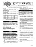
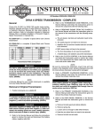
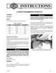
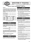
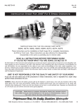
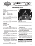
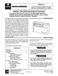
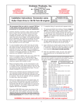
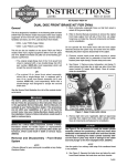
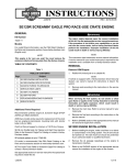
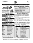
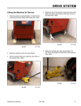
INSTRUCTIONS
®
REV. 02-11-2005
-J03322
Kit Number 33136-04 and 33137-04
SCREAMIN’ EAGLE® FLHT 6-SPEED TRANSMISSION
General
Installation
The Screamin’ Eagle FLHT 6-Speed Transmission kit fits
2002 and later Harley-Davidson ® Touring model
motorcycles.
Prepare the Motorcycle for Service
Kit No.
33136-04
33137-04
Description
Silver
Black
Gear
1st
2nd
3rd
4th
5th
6th
5-Speed
3.210
2.109
1.572
1.226
1.000
NA
2. Follow Service Manual instructions given to remove the
seat.
6-Speed
3.210
2.209
1.572
1.226
1.000
0.885
Table 1. Transmission Ratios
An additional kit for the side cover will be required. The kit
number depends on if the motorcycle is using the existing
clutch cable or is being converted to a hydraulically actuated
clutch.
Kit No.
38752-04
45033-03A
45383-03A
38753-04
1. Mount the motorcycle on a suitable lift.
Description
SE 6-Speed Cable Clutch Side
Cover and Release Pushrod Kit
Hydraulic Clutch Kit - black
Hydraulic Clutch Kit - chrome
SE 6-Speed Hydraulic Side Cover
& Release Kit
See the Service Parts illustration for a list of service parts in
this kit.
Required Service Parts and Tools
Installation of this kit will require additional service parts and
supplies. Specialized tools will include Hose Clamp Pliers
(HD-41137) and Hose Clamp Pliers (HD-97087-65B).
1WARNING
The rider's safety depends upon the correct installation
of this kit. If the procedure is not within your capabilities
or you do not have the correct tools, have your HarleyDavidson dealer perform the installation. Improper
installation of this kit could result in death or serious
injury. (00308a)
NOTE
This instruction sheet references Service Manual instructions. A Service Manual for your model motorcycle is available from any Harley-Davidson dealer.
1WARNING
To prevent accidental vehicle start-up, which could
cause death or serious injury, disconnect battery cables
(negative (–) cable first) before proceeding. (00307a)
1WARNING
Disconnect negative (–) battery cable first. If positive (+)
cable should contact ground with negative (–) cable connected, the resulting sparks can cause a battery explosion,
which could result in death or serious injury. (00049a)
3. Disconnect the battery cables, negative (-) cable first:
a. Remove bolt and negative (–) cable.
b. Remove bolt and positive (+) cable.
Access the 5-Speed Transmission
1. Place a container under the engine, remove the engine
and transmission lubricant drain plugs to drain engine
and transmission fluids.
2. To access the existing 5-speed transmission, follow the
Service Manual instructions in the following sections:
a. SADDLEBAGS, REMOVAL
b. EXHAUST SYSTEM, REMOVAL
NOTE
The right muffler and crossover pipe can be removed in 1
piece and the left muffler and the front and rear header
pipes can be removed in 1 piece. Refer to the Service
Manual Section REMOVING ENGINE FROM CHASSIS for
instructions.
c. REAR WHEEL. REMOVAL
NOTE
Position a jack with a wooden block under the engine and
transmission oil pan to support the weight of the 5-speed
transmission.
d. REAR SWINGARM, REMOVAL
e. STARTER, REMOVAL
f. CLUTCH RELEASE COVER
1 of 6
Remove the Primary Chaincase
i06775
Follow the Service Manual PRIMARY CHAINCASE,
REMOVAL instructions to remove the cover, the primary
chain, clutch, engine compensating sprocket, chain
tensioner assembly, alternator and starter drive mechanism,
and the primary chaincase.
Remove the 5-Speed Transmission
1. Remove the locknut, lockwasher and flat washer to
separate the the shift rod from the 5-speed transmission shifter arm.
2. Remove oil hose cover and oil hoses at the crankcase.
a. Remove screws and cover.
b. Use side cutters to remove clamps on crankcase end
of oil supply, return and crankcase breather hoses.
Figure 1. Vehicle Speed Sensor
(behind engine oil fill plug/dipstick)
3. See Figure 1. Locate vehicle speed sensor and remove
screw and the sensor from the existing transmission
case.
4. See Figure 2. Remove connectors from neutral switch.
i06782
5. See Figure 3. Remove the fasteners from the transmission exhaust bracket.
6. Remove the 4 bolts and washers connecting the transmission to the engine.
NOTE
After removing the bolts, the transmission is unattached to
the frame or the engine and is resting on the support jack.
7. See Figure 4. From the right side, slide the transmission
toward the rear of the motorcycle (to clear the ring dowels) and lift the transmission out of the frame.
Figure 2. Neutral Indicator Switch Connector
Install 6-Speed Transmission
1. Slide the 6-speed transmission with oil pan from the right
side of the frame into position.
i06771
a. Center the the transmission rear mounts between the
rear swingarm mounts.
b. See Figure 4. Move transmission forward to engage the
2 ring dowels in the lower flange of crankcase.
2. Align the bolt holes on the transmission to the engine by
threading in and finger tightening the 4 bolts and washers.
NOTE
Use OPEN End Crowfoot (Snap-On FC018) on the upper
left and upper right transmission housing to crankcase bolts.
3. See Figure 5. Tighten the transmission bolts in a cross
pattern torque sequence:
a. 1st pass tighten to 15 ft-lbs (20.3 Nm).
b. 2nd pass tighten to 30-35 ft-lbs (40.7-47.5 Nm).
Figure 3. Exhaust Bracket on 5-Speed Side Door
(side cover removed)
4. Assemble the pivot shaft assembly (pivot shaft, locknut,
cup washer, rubber mount and outer spacer) and coat
the pivot shaft with Loctite® Anti-Seize.
-J03322
2 of 6
5. Slide rear swingarm assembly into position aligning with
mounting boss of transmission case.
i06772
6. Follow the Service Manual REAR SWINGARM INSTALLATION instructions to position the rubber mounts in
the rear swingarm bracket
7. Install pivot shaft and tighten locknut to 45-50 ft-lbs
(61.0-67.8 Nm).
8. Install the flat washer, lockwasher and locknut to fasten
shifter rod to the new 6-speed shift lever. tighten locknuts to 80-120 in-lbs (9.0-13.6 Nm).
9. Install the exhaust bracket and tighten bolts to 13-16 ftlbs (18-22 Nm).
10. Install oil supply, return and breather hoses.
a. Fit new clamps onto ends of hoses.
b. Push and push hoses onto oil fittings
c. Crimp supply and return clamps with Hose Clamp
Pliers (HD-41137).
Figure 4. Ring Dowels
(oil filler spout and side cover removed)
d. Crimp breather hose clamp with Hose Clamp Pliers
(HD-97087-65B).
11. Secure oil hose cover to transmission and alternately
tighten screws to 84-108 in-lbs (10-12 Nm).
i06779
2
12. Install the vehicle speed sensor and tighten to 84-132
in-lbs (9.5-14.9 Nm).
4
13. Push the neutral indicator light connectors onto the
neutral indicator switch.
Install Primary Chaincase
1. Follow the Service Manual PRIMARY CHAINCASE,
INSTALLATION instructions to install the primary chaincase, primary chain, clutch, engine compensating
sprocket, chain tensioner assembly, the starter drive
mechanism and the chaincase cover.
2. Remove the inspection cover.
Install Side Cover Release Kit
3
1
Install the side cover.
For cable actuated clutch: Follow the instructions in
the SE 6-Speed Cable Clutch Side Cover and Release
Pushrod Kit (Part No. 38752-04).
For hydraulic clutch: Follow the instructions in the
Hydraulic Clutch Side Cover and Release Pushrod Kit
(Part No. 38753-04) and in the Hydraulic Clutch Kit
(Part No. 45033-03 - black or 45388-03 - chrome).
Figure 5. Transmission to Crankcase Torque Sequence
(transmission view from front)
Install Removed Components
1. To install the components removed to access the 5speed transmission, follow the Service Manual instructions in the following sections:
a. REAR SWINGARM, INSTALLATION
b. REAR WHEEL, INSTALLATION
c. STARTER, INSTALLATION
d. EXHAUST SYSTEM, INSTALLATION
e. SADDLEBAGS, INSTALLATION
-J03322
Instructions continued on page 6.
3 of 6
®
Service Parts
Date 02/05
Part No. 33136-04 & 33137-04
Screamin’ Eagle FLHT 6-Speed Transmission
i06787
45
75
46
56
27
1
2
17
47
80
16 15 17
58
29
79 68
19
ADD
QUART
74
70
57
FULL HOT
76
DO NOT OVERFILL
76
69
68
78
43 41
48
63 62
64
36
26
30
35
55
48
23
44
66
72
31 54
73
59
77
50
42
34
39
65
28
13
38
9 33
i06801
69
8
61
61
4
6
25
38
38
24
12 25
11
7
38
38
11
10
14
33 25
25
14
38
i06803
53
52
12
5
25
38
6
53
50
51
8
18
3
i06799
38
40
22
-J03322
37
21
19
54
20
4 of 6
®
Item
1
2
3
4
5
6
7.
8
9
10
11
12
13
14
15
16
17
18
19
20
21
22
23
24
25
26
27
28
29
30
31
32
33
34
35
36
37
38
39
40
41
42
43
44
45
46
Service Parts
Description (Qty)
Gasket, sensor plate
Plate, sensor
Gear, countershaft 4th
Gear, mainshaft 1st
Gear, countershaft
Gear 3rd main/2nd counter (2)
Gear, mainshaft 4th
Gear, 3rd counter/2nd main (2)
Gear, mainshaft 6th
Countershaft
Mainshaft
Shift ring 1_2, 3_4 (2)
Shift ring 5_6
Spline sleeve (2)
Shift fork assembly 1_2
Shift fork assembly 3_4
Shift fork assembly 5_6
Shift drum assembly
Pin, shift drum (6)
Retainer, shift drum
Support assembly, left cam w.bearing
Locknut, mainshaft & countershaft (2)
Gear, mainshaft 5th
Gear, countershaft 5th
Split gage bearing (5)
Screw, lower trap door (4)
Screw, speedo sensor plate
Screw, pillow block (4)
Screw, upper side cover (4)
Screw, lower side cover (4)
Screw, trap door, upper (2)
Screw, shift fork shaft
Thrust washer, main/countershaft (2)
Washer, shifter seal
Sprocket spacer
Mainshaft race
Retaining ring, door (2)
Retaining ring, main/countershaft (8)
Retaining ring, shifter
Bearing, trapdoor (2)
Seal, main case
Seal, shifter
Quad seal
Gasket, trap door
Gasket, side cover
Gasket, oil spout
-J03322
Part No.
35152-03
35153-03
35136-03
35134-03
35080-03
35083-03
35104-03
35135-03
35131-03
35059-03
35058-03
35137-03
35138-03
35140-03
35143-03
35144-03
35145-03
35142-03
33385-02
11242
33301-00A
35078-79
35237-03
35238-03
8876A
3249
3594
3909
4717A
4718A
4814A
3784
6003
6497HW
33344-94
34091-85A
35087-99
11067
11150
8992A
12067B
12045
11165
35147-03
35148-03
62432-93B
Part No. 33136-04 & 33137-04
Date 02/05
Screamin’ Eagle FLHT 6-Speed Transmission
Item
47
48
49
50
51
52
53
54
55
56
57
58
59
60
61
62
63
64
65
66
67
68
69
70
71
72
73
74
75
76
77
78
79
80
Description (Qty)
Part No.
Gasket, lid
34904-86D
Shaft, shift fork
34088-87A
Support assembly
33304-00
Sleeve, detent arm spring
33375-00A
Detent follower assembly
33364-00A
Spring, detent arm
33374-00
Pivot screw, detent arm
33376-00
Trapdoor, chrome no ear
35158-03
Plug, drain door
45830-48
Dipstick, O-ring
11132
Dipstick, chrome transmission
37075-87
O-ring, speedo sensor
11289A
Shifter shaft assembly
35146-03
Pin, roll
634
Switch, neutral indicator/O-ring
33904-00
Meganut
35236-03
Sprocket, transmission 32T
40250-94C
Screw, meganut (2)
4069A
Screw, lever
856A
Lever, shifter rod
33849-97
Centering pin
34978-00A
Screw, top cover (8)
4740A
Transmission cover, chrome
34541-00
Vent hose
42533-91A
Fitting, upper cover
62375-57A
Screw, oil pan (12)
4741A
Gasket, oil pan
26077-99A
Hose, oil (2)
62726-99
Clamp (2)
10249
Hose, crankcase to tank vent
45808-02
Oil pan assembly
black
62489-99
silver
62490-99
Filler cap, engine oil
black
62846-99
silver
62849-99
Oil filler spout assembly
black
62455-02
silver
62456-02
Trans case assembly
black
34839-04
silver
34838-04
Trans case (black & silver) - subcomponents
Retaining ring
11161
Bearing, main
8996A
Bearing, closed end
8977
5 of 6
Replace Lubricants
Return the Motorcycle to Service
1WARNING
Be sure that no lubricant gets on tires, wheels or brakes
when changing fluid. Traction can be adversely affected,
which could result in loss of control of the motorcycle and
death or serious injury. (00047a)
1. Follow the Service Manual PRIMARY CHAIN/LUBRICANT, PRIMARY CHAIN LUBRICANT to fill the primary
chain case:
a. Verify that the drain plug/O-ring is installed and
tighten to 36-60 in-lbs (4.1-6.8 Nm).
b. Fill with 32 ounces (946 ml) of Harley-Davidson
Primary Chaincase Lubricant through inspection
cover.
c. Follow the Service Manual to install a new gasket and
cover. Tighten the cover screws to 84-108 in-lbs (1012 Nm).
2. Follow the Service Manual TRANSMISSION LUBRICANT, PROCEDURE to fill the transmission with lubricant:
a. Verify that the transmission drain plug/O-ring are
installed in the pan and tightened to 14-21 ft-lbs (1928 Nm).
b. Remove the filler plug/dipstick and fill the transmission
with 20-24 oz. of Harley-Davidson Semi-Synthetic
Transmission Lubricant. Fill until the level is at the F
(FULL) mark with the motorcycle upright.
c. Tighten the filler plug to 25-75 in-lbs (2.8-8.5 Nm).
3. Follow the Service Manual ENGINE OIL/FILTER, PROCEDURE to fill the oil tank and engine with oil:
a. Verify that the the engine drain plug/O-ring is installed
in the pan and tightened to 14-21 ft-lbs (19-28 Nm).
c. Through the oil filler/dipstick spout, fill with 3 1/2 (3.3
liters) of the grade of oil specified for the lowest
ambient operating temperature.
d. Follow Service Manual instructions to perform an
engine oil level COLD CHECK and add as required.
4. For hydraulic clutch: If installing a Hydraulic Clutch
Side Cover and Release Pushrod Kit (Part No. 3875304) and a Hydraulic Clutch Kit (Part No. 46414-05 chrome or 46415-05 - black), follow the instruction sheet
in the kit to fill and bleed the clutch fluid lines.
-J03322
1. Follow the Service Manual REAR BELT DEFLECTION
instructions to measure and adjust drive belt deflection.
1WARNING
Connect positive (+) battery cable first. If positive (+) cable
should contact ground with negative (–) cable connected,
the resulting sparks can cause a battery explosion, which
could result in death or serious injury. (00068a)
2. Connect the battery cables, positive cable first.
a. Tighten the bolts to 60-96 in-lbs (6.8-10.9 Nm).
b. Coat both terminals with Electrical Contact Lubricant
(Part No. 99861-02).
c. Rotate the hold-down clamp to rest the rubber pad on
the battery edge. Tighten to 15-20 ft-lbs (20-27 Nm).
1WARNING
After installing seat, pull upward on front of seat to be
sure it is in locked position. While riding, a loose seat
can shift causing loss of control, which could result in
death or serious injury. (00070a)
3. Follow Service Manual instructions to install the seat.
4. Turn ignition/light key to IGNITION to verify neutral indicator lamp illumination in neutral.
Test Ride Motorcycle
1. Test ride the motorcycle.
a. Shift into and out of each gear.
b. Shift into and out of neutral.
c. Verify operation of speedometer and vehicle speed
sensor.
2. Follow Service Manual instructions to perform an engine
oil level HOT CHECK.
Initial Service
Follow the Service Manual instructions to replace the transmission lubricant after 500 miles.
NOTE
After the initial service, follow the Scheduled Maintenance Table
in the Service Manual and change the engine and transmission
fluids at scheduled service intervals.
6 of 6