1
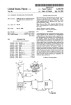
GOVER N MEN TAL
SE CUR ITY
SOL UTIO NS
Product Information
GSM - Monitoring System
Semi Active - FALCON E+
User Manual
GSM-Monitoring System Semi Active
FALCON E+
User Manual
Contents
1. Introduction .........................................................................................................................4
2. System Components...........................................................................................................4
3. Operating Modes ................................................................................................................4
3.1. Mode “IMSI catcher”...................................................................................................4
3.2. Mode “Normal operation” ...........................................................................................4
4. Setting of the parameter for the BTS „Inner Network“ ......................................................8
5. Support..............................................................................................................................12
5.1. Guarantee ...................................................................................................................12
5.2. Customer Service, Hotline..........................................................................................12
Introduction
Falcon E+ system is based on the Software platform for the other Falcon systems
(Falcon C+ and Falcon D+) with some significant enhancements. This was required in
order to be able to fulfil the different tasks, such as surveillance of every GSM
network and GSM connections. With the new system Falcon E+ it is possible to
monitor unnoticed the activities on GSM networks using the A5.1 encryption
algorithm.
System Components
A system consists of:
•
Base station (BTS), used for GSM-900 or GSM-1800 networks (customised
configuration according requirement);
•
FALCON Main Unit/ Mobile station (MS) (number of Up - and Down - Links
according customers requirement, but not more than - 2);
•
Active Station (AS) (Number of channels according customer requirements,
not more than 4);
•
Paging - Station (PGS) 1 unit;
•
Notebook with Monitoring Software (PC);
•
Power Supply Units (PS1-PS3) (3 units);
•
Power Adapter (NA);
•
Directional Antenna (A1) for GSM - network;
•
Omni directional Antenna (А2) for GSM - network;
•
Connecting cable.
Option: Power Amplifier for Base station (AMP) with Power Supply Unit (PS4) and
additional Directional Antenna for GSM – network (A3) (Fig.1)
Operating Modes
Mode “IMSI catcher”
This Mode is the „Main Mode“ of the Falcon E+ SYSTEM.
The System Software initialises the Falcon E+ BTS. The BTS builds up an “Inner
GSM network” with network identical MCC, MNC and ARFCN and with the same
parameters as the “outer GSM network”. The only difference to the existing GSM
network is the LAC.
Mobile Phones (target) in the range of the covered area are now log on to the new
„artificial“ (inner) BTS and start with the registration procedures with this „new“
BTS. During this registration process the mobile phone submits the IMSI, IMEI, TMSI
(received earlier from the “real” GSM network), “classmark” and KCN. The
registered mobile phones are listed and displayed at the “BTS control” of the Falcon
E+ control unit (Notebook).
The main advantage of the system is the fact that the registration on the artificial BTS
does not differ from the registration on the real GSM network.
Mode “Normal operation”
Similar to the mode «IMSI catcher» the software controls the following modules:
•
Station of the paging - channels – for monitoring and registration of the calling
data, sent from the „real“ GSM network to the users (targets).
•
Mobile station – to support the authentication process through the real GSM
network, during the process of outgoing and incoming calls to the users (targets)
„caught“ by the artificial BTS.
CONFIDENTIAL
4
The mobile stations are automatically adjusted to the ARFCN channel of the artificial
network.
•
Active stations – used to link the target mobile phone with the real GSM
network and acting as interface between the „Inner“ and „Outer network“ (repeater)
After system power-on, and the registration of the targets, the Falcon E+ works fully
automatically:
а) The target does not receive calls and is not calling (Standby Mode).
If a mobile user (target) doesn’t need to be monitored, the relevant entry in the list of
registration has to be marked. After a time interval of 6 Minutes, the target will start
its periodical registration to the artificial BTS. The software supports this function and
requests the target to remain connected to the artificial BTS or to leave the artificial
BTS and to connect to the real BTS if it was allowed by the Falcon E+ operator. If the
target connects to the real BTS the target will be removed from the List of
registration.
Remark: A target will also be removed from the List of Registration if the target does
not start its registration procedure to the artificial BTS within 6 minutes. It may have
been a mobile phone passing by (in a car) and caught during that short time period.
b) The listed target starts a call or sends a SMS
One of the idle Active Station (AS) attached to the Falcon E+ will act as the target
and works as link between the “artificial” BTS and the real network. It simulates the
real target. If all Active Stations (AS) linked to the real network are busy, a “network
busy” message will be displayed.
The target will send all data and technical information to the Active Station (AS) and
this Active Station acts as a repeater, transmitting the data received from the target
into real network.
All calls incoming from the real network will be received by the Active Station (AS)
and forwarded to the target (AS works as a repeater). This procedure is not
noticeable for the targeted user. There will be no “strange” messages on the targets
display or unusual behaviour.
c) The registered target receives a call or a SMS
One of the idle Active Station (AS) attached to the Falcon E+ will acts the target and
works as a link to the real network. It simulates the real target. If all Active Stations
(AS) linked to the real network are busy, a “number cannot be reached” message
will be displayed at the call originating phone.
The paging station will register the call of the target, will generate a call to the target
and will wait for the connection. Once connected the Active Station (AS) will transmit
all data from the target to the real network. All incoming calls and SMS sent from the
real network to the target will be first received by the Active station and then routed
to the target. The Active Station acts like a repeater system. The entire procedures
remain unnoticed by the target. There is no info on the display of operational
malfunctions which could compromise the monitoring System.
System preparation for active operation
Prior to the operation of the system, a deeply analysis of the GSM environment of
the targeted area has to be carried out. Users, which are not targeted, have to be
CONFIDENTIAL
5
deleted from the List of registration. It is essential to know on which network
provider the target is operating.
Important: The USB cable between the modules and the Notebook has to be
connected before switching on the Power Supply Unit.
Cable connections are according Fig.1
(Fig.1)
Switch on the power supply units for all of the modules. (~220 VAC). Place the
module of the active mobile units vertically with the front towards the operator and
the rear towards the target. Place the antenna A1 straight towards the target. The
Base Station (BS), simulating the artificial network should be placed within the range
of 5 to 20m from the unit with the mobile stations to avoid interference. Place the
omni-directional antenna A2 close to the Base Station (BS) of the artificial network,
power on the note book and start the application software. If started the first time,
please confirm with ok (fig. 2)
(Fig. 2)
Wait until the application software is completely loaded (Fig. 3)
(Fig. 3)
The display shows the main menu (fig.4). The indicators at the top right are showing
the status of the system, if green, the system is ready for operation. The start-up and
initialling phase may take up to 3 minutes.
CONFIDENTIAL
6
Remark: Green indicated the successful start-up of the systems. If the indicator don’t
switch to green, the system has not been successfully started. Please reboot the
system.
(Fig. 4)
1.
Indicator - normal operation of the BTS in the „inner network“,
2.
Indicator - normal operation of the decoders;
3.
Window - List of the registered mobile users (targets);
4.
Key for the pop-up menu for the BTS (inner network) adjustments.
5.
Window - Recorder (number of recorders according the numbers of the active
mobile stations)
6.
Window - Targets;
7.
Window - active stations;
8.
Station Paging - Channel (within the same window as the active stations
because they are physically in the same housing);
9.
Window - Mobile station;
10.
Protocols (the MSV1-6 are according the protocols of the data exchanges
between the inner and the outer network of the active stations. The status MS1-4 are
according the mobile stations and AS1-5 are for the test messages of the active
stations, BTS main displays information of the messages routed through the BTS of
the inner network.
Window 7 and 9 are not started automatically. For activations please select
“Windows”, “Receiver Window” and then “Active Stations Window”
(Fig.5)
As soon as the system is ready for operation, the parameters of the “Inner Network”
have to be set.
CONFIDENTIAL
7
Setting of the parameter for the BTS „Inner Network“
After the successful start of the application software, the two indicators 1 and 2 are
green (Fig 4). Open windows “Receivers Window“ and the „Active stations
window“ as described above. Use key 4 for changing to parameter settings of the
BTS of the “Inner Network” (Fig. 6)
(Fig. 6)
Enter in the field „Net LAI“ the 5 digits of the GSM - Providers LAI (MCC+MNC) in
which the target mobile phone has registered its SIM card e.g. MCC=180, MNC=01.
After the hyphen enter the word „any“. All other parameters enter according Fig 6.
Enter ok, close the window and restart the application software. After the restart the
active stations will automatically scan the network and will select the strongest
BCCH Channel
.
Remark: Some channels may have been allocated to a different LAC. Some of the
incoming calls might be lost since the system has only one paging station.
The target will be most likely connected on the same channel of the “outer BTS”.
The target will get continuously information about neighbouring channels and signal
strength. Those data are also received by the Falcon E+. The Falcon E+ will generate
its own list. The list is displayed in the window ARFCN group „BTS parameters“(Fig.
7).
Switch to the window with the active stations and analyse the LAC. Note the most
displayed LAC number (e.g. the number 111111).
Switch to the window with the parameter settings of the „Inner Network“ BTS
(Fig.6).
CONFIDENTIAL
8
(Fig. 7)
Select the window „ARFCN“, and „BTS parameters“ (Fig. 7). The list shows the
active neighbouring channels at the left and at the right it shows the signal level of
the channels. Select the channel with the weakest signal (lowest level), according Fig
7, it would be the channel number 777. It will be highlighted blue and the signal level
is -99 dB. The field “ARFCN” will be up-dated automatically with the parameters (Fig
7.). The “inner BTS” will get operational with a signal level stronger than the one
from channel 777.
Enter in “net LAI” and “BTS parameters” the 5 digits LAI (MCC+MNC) of the
network provider in which the target is registered, e.g. MCC=180, MNC=01 after the
hyphen type in earlier noted LAC (e.g. LAC number 11111).
Enter in the field “nano BTS LAI” and “BTS parameters” the 5 digits LAI
(MCC+MNC of the GSM network provider in which the target is registered, e.g.
MCC=180, MNC=01). Enter after the hyphen the LAC (LAC 111) which is different
than the earlier detected. The “Inner Network” has now the LAC number 111.
Enter in the field „TX pwr red lev“, „BTS parameters“ a even number between 0 and
12. This parameter is controlling the output power of the BTS of the “Inner
Network”. Maximum output power (maximum operating range) is set with the
number 0, the minimum power is set with the number 12 (minimum operating
range).
Confirm the parameters by pressing ok and restart the system.
The above mentioned Set-ups are described in detail as follows:
Assumption:
The target is controlled by the protocol 180-01 (EISS-ISAC) of the network provider.
The target is within the range of LAC 1111. The target has continuous information
about the neighbouring channels and is updated from the BTS, according our
example with the channel number 777 is received with a very weak signal.
Reason for fine tuning:
A new connection is made by the provider with 180-01 (EISS-ISAC) which has a
much stronger signal than channel 777. The target detects this strong signal and tries
to log in, also because the LAC from the „Inner Network“ and the „Outer Network“
CONFIDENTIAL
9
is different. The target transmits its IMSI, KCN, classmark and IMEI, which allows the
Falcon E+ to clone and trace the target.
After the restart the two indicators 1 and 2 will be green. (Fig 4)
Operation with the list of registered users.
After the initial setting up of the Falcon E+ and its fine tuning it is important to
receive a sufficient strong signal level for the Mobile Stations MS 1 and 2 (Fig 4) of
the „Inner Network“ BTS.
Wait until the two Indicators (1 and 2, Fig 4) are switching to green and only then
open the window “Receivers Window”, Fig 5. The down link signal should be in the
range of -50 to -60 dB and the up-link signal should be in the range of -70 to -75 dB.
In order to get these values, the distance between the Mobile Stations (MS) and the
Base Station (BTS) has to be adjusted (20m or more).
The system will automatically start the mode “IMSI catcher” and the Window 3 (Fig
4) will display the registered users (Fig.8).
(Fig.8)
The field «NAME» shows the name of the target, if the system can allocate its
parameters and identification in the List of Targets.
The field «IMSI» shows the IMSI of the registered user.
The field «LAI» shows the values MCC and MNC of the GSM network provider and
the LAC where the target has been connected earlier.
Remark: It is possible that the field LAI will display 18001-any. This value indicates
that the target has not transmitted its TMSI. The detected value of the KCN is 7. The
next connection will expect the transmission of the IMSI. A calculation of the
communication key KC is not possible. In such cases the system calculates the KC
from outgoing and incoming calls. Display of statistical information
1
2
3
4
6
5
7
(Fig.9)
1.
2.
3.
MS1;
4.
MS2;
5.
6.
Number of registered users in the “Inner Network”
Number of registered users with known TMSI (from the „outer network“)
Number of calculated communication keys КС through connection by the
Number of calculated communication keys КС through connection by the
Total number of calculated communication keys KC;
Total numbers of the random access data packages in the paging-channel;
CONFIDENTIAL
10
7.
Total numbers of the random access data packages in the paging-channel
handled by the Falcon E+ system
The field „КС“ displays the value of the currently used communication.
The field «LAST EVENT» displays the value of the last registered events (registration,
periodical registration of the user, outgoing calls, incoming calls, etc.).
The field „LAST EVENT TIME“ displays the starting time of the last events.
The field „TIME LIMIT“ displays the value of the timers Т3212 for the validity of the
TMSI.
The field „HLR STATUS“ displays the status of the user in the „inner network", when
registered first time, the displays shows “Acceptable MS” (registration in the “inner
network allowed). These parameters are refreshed every 6 minutes.
The field «RXLEV» displays the level of the received signal when disconnected.
«LAST EVENT». This parameter indicates the distance from the „Inner network“ BTS
and the target. The stronger the signal the nearer is the target.
CONFIDENTIAL
11
Support
Guarantee
It applies a legal guarantee period of 12 months for material and faulty manufacturing.
There is no further, explicit or tacit guarantee possible.
The manufacturer is not responsible for sequence damages.
The warranty claim expires if repairs or interventions are done by persons who were
not authorised by the manufacturer.
Errors which occurred due to an inappropriate use of the device, incorrect maintains
or the use of accessories or special accessories not advised by the manufacturer do
not fall under guarantee.
It is in no case allowed to open the device.
Any installation procedures for the programs presuppose an in itself conflict-free
operating system.
Problem solutions for it require either an intensive detail knowledge of the used
system or its compromise less reconstruction.
The manufacturer does not take over any guarantee for that the programs or systems
used by the user will furnish the striven utility.
Should any warranty return take place, it has before to be agreed by the
manufacturer. Otherwise, it will not be handled.
The manufacturer does not take over any transport damages or transport insurances.
Any unfranked letter or parcel will not be accepted. If there is no error of the product
found, a handling charge will be raised.
Customer Service, Hotline
Support is generally done by
IBH-IMPEX Elektronik GmbH
Friederikenplatz 55 a
D-06844 Dessau
Tel.: +49 340 2400242
Fax.: +49 340 2400244
E-Mail: [email protected]
CONFIDENTIAL
12
S OL UT I O N S
S ECU RITY
GOVE RNM E NTA L
If you would like further Information about ELAMAN,
or would like to discuss a specific requirement or project, please contact us at:
Elaman GmbH
German Security Solutions
Seitzstr. 23
80538 Munich
Germany
Tel: +49-89-24 20 91 80
Fax: +49-89-24 20 91 81
[email protected]
www.elaman.de