1
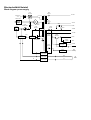
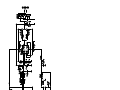
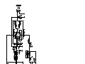
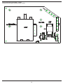
Serviceanweisung
Service manual
Chassis TV 17XL
Versionen:
TV17XL.4
TV17XL.7
TV17XL.C
TV17XL.D
TV17XL.E
TV17XL.F
Chassismerkmale / Featurelist Chassis TV17XL
CHASSIS CODE
TV17XL.4
TV17XL.7
TV17XL.C
TV17XL.D
TV17XL.E
TV17XL.F
CHASSIS TYPE
100 Hz
100 Hz
100 Hz
100 Hz
100 Hz
100 Hz
SOUND
Stereo
Stereo
Stereo
Stereo
Stereo
Stereo
Picture tube size
32"
28"
29"
32"
29"
32"
Picture tube format
16:9
4:3
4:3
16:9
4:3
16:9
W76 ESF 021X44 Philips
Super Flat
A66 EAK 075X44 Philips
A68 ELO 50X71 Panasonic
Real Flat
W76 EKW 10X71
Panasonic Real Flat
A68 EGD 049X622
Thomson Super Flat
W76 ELE 50X71
Panasonic Real Flat
double
single
single
double
single
double
half
half
half
full
half
full
Digital CTI
+
+
+
+
+
+
Digital Combfilter
+
+
+
+
+
+
Dynamic Peaking
+
+
+
+
+
+
SVM (Scan Velocity Modulation)
+
-
+
+
-
+
Frame Rotation
-
-
+
+
-
+
LSC (Light Sensor Control)
-
-
+
+
+
+
4:3, Decoder, 16:9, Zoom
4:3, Decoder, 16:9, Zoom
4:3, Decoder, 16:9, Zoom
4:3, Decoder, 16:9, Zoom
4:3, Decoder, 16:9, Zoom
4:3, Decoder, 16:9, Zoom
Picture tube
Single focus / Double focus
PICTURE
Frame Buffer
SOUND
Picture Formats
PIP (2 Tuner)
+
-
-
-
-
-
Mulitbild 4x / 12x / 16x
+
+
+
+
+
+
Mono/A2-Stereo/NICAM
+
+
+
+
+
+
AV Stereo
+
+
+
+
+
+
Dolby Virtual Surround Sound
+
+
+
+
+
+
2-way loudspeakers
+
+
+
+
+
+
2x 12W
2x 10 W
2x 10 W
2x 10 W
2x 10 W
2x 10 W
+
+
+
+
+
+
ELECTRONIC
CONNECTIONS
TUNING
Sound output
PLL Frequency Synthesizer Tuner (European
Channel Table, VHF / UHF, C02 - C76, S01 - S41)
TV-standard
PAL B/G
PAL B/G
Multi
Multi
Multi
Multi
Cable TV / Hyperband(S1-S41)
+
+
+
+
+
+
Euro-scart socket 1 (CVBS In/Out, S-VHS In, RGB
In, Audio L+R In/Out )
+
+
+
+
+
+
Euro-scart socket 2 (CVBS-In, Audio L+R In)
+
+
+
+
+
+
Euro-scart socket 3 (CVBS-In, Audio L+R In)
+
+
+
+
+
+
Audio /Video In (Cinch) (Front or Side)
+
+
+
+
+
+
Headphones (3,5 mm jack)
+
+
option
+
+
+
Aerial Input (75 ohms antenna)
+
+
+
+
+
+
Manual & automatic labelling of presets
+
+
+
+
+
+
Programmable timer
+
+
+
+
+
+
Programme memory TV/AV (opt.)
99 + 4 AV
99 + 4 AV
99 + 4 AV
99 + 4 AV
99 + 4 AV
99 + 4 AV
Teletext memory pages
500 pages
500 pages
500 pages
500 pages
500 pages
500 pages
Childlock (Preset / A/V)
+
+
+
+
+
+
Menu languages OSD
12
12
12
12
12
12
Service mode menue
+
+
+
+
+
+
Front keys
+
+
-
-
-
-
0,5 W
0,5 W
0,5 W
0,5 W
0,5 W
0,5 W
RC 221
-
+
+
+
+
+
RC 2000
+
-
-
-
-
-
RC900
-
-
+
+
+
+
RC
Power consumption Stand-by
Bedienungshilfe
Assistance for operation
RC 221
ausschalten
switch off
Programmplatzwahl
select the program
Ton ausschalten
mute - sound off
Info-Taste / Menü-Führung
info-button /menu guiding
Lautstärkeeinstellung / Menü-Führung
volume setting / menu guiding
Programmforschaltung / Menü-Führung
select program step by step / menu guiding
Speichertaste
memory button
Menüs ausblenden
fade out the menus
Tonmenü /Menü-Führung
sound menu / menu guiding
Videotext
videotext
VT
Bildmenü / Menü-Führung
picture menu / menu guiding
Bild in Bild (PiP)
picture in picture (PiP)
VCR
VCR Bedienung
VCR control
Durch Drücken der Info-Taste » i « erscheint auf der
linken Bildschirmseite das Info-Menü. Rechts neben dem
Info-Menü erscheint das angewählte Untermenü.
Info-Menü
Bild
Ton
Klang
Programm
PiP
Dolby
System
Spezial
Timer
Kisi
Abschnitt der Bedienungsanleitung
Bild und Ton
Programme einstellen
Bild im Bild (PIP)
Dolby Tonübertragung
Sonderfunktionen
Mit den Tasten »5 / 6« wird die grüne Markierung zum
Thema der entsprechenden Untermenüs geführt. Durch
Drücken der Taste »4« gelangt die Markierung in das
gewählte Untermenü.
Um aus den verschiedenen Untermenüs zurück zum InfoMenü zu gelangen mit den Tasten »5 / 6« < zurück
anwählen. Durch Drücken der Taste »3« gelangt die
Markierung zurück ins Info-Menü.
Zum Speichern die Taste » OK « drücken; die Einblendung „OK.. speichern“ wird kurz rot. » TV «Taste drücken um das Menü zu verlassen.
Funktionstasten
function buttons
The Info Menu appears on the left side of the screen by
pressing the » i « information key. The selected submenu appears to the right next to the information menu.
Info menu
Picture
Sound
Tone
Program
PiP
Dolby
System
Special
Timer
Child
Section of operating instructions
Picture and sound
Programme setting
Picture in picture (PIP)
Dolby sound transmission
Special functions
The green marker is moved to the relevant sub-menu
item with the »5 / 6« buttons. The marker moves to the
selected sub-menu by pressing the »4« button.
Select < back with the »5 / 6« buttons to return to the
info menu from the various sub-menus. The marker
moves back to the info menu by pressing the »3« button.
To store a setting, press the » OK « button; “OK.. save”
is temporarily displayed in red. Press the » TV «-button to
leave the menu.
Service-Mode Abgleichhilfe TV 17 XL
Service-mode alignment table TV17XL
version – number
NVM – reset
picture - size
picture – tube
TV – type
tuner – type
front av
scart number
forced PAL
function keys
VT pages
display – mode
testpattern
auto. format
XL x.xx
Off
sleep timer (5min)
ECO switch
child lock-code global
child lock-code reset
audio VCR mute
VT brightness
VT contrast
OSD brightness
OSD contrast
OSD background color
OSD foreground color
VGA – modus
VPS / PDC – display
rotation
mode analog channel 2
display values
ext. scart
waterglass / panorama
format
AGC
vertical amplitude
vertical position
s – correction
vertical symmetry
vertical bow
vertical angle
horizontal position
horizontal amplitude
cushion
trapeze
upper corner
Off
lower corner
blanking phase left
blanking phase right
chroma delay
luma delay
newline
DVCO
G2
autom. alignment
only for G2-alignm.
cut off red / green / blue
measured
R
controlled
R
NVM
G
G
B
B
white drive red / green / blue
measured
R
G
controlled
R
G
NVM
B
B
Off
SVM G1
SVM delay
beam current limiter
vert. pos OSD
hor. pos OSD
vert. pos OSD (NTSC)
hor. pos OSD (NTSC)
vert. pos VT
hor. pos VT
child lock reset
border (16:9) right
border (16:9) left
edit run text
multi – pip modus
TV settings:
cushion
hor. pos.
hor. ampl.
vert. pos.
vert.ampl.
PIP – settings
hor. pos.
hor. ampl.
vert. pos.
NVM addr. 0000
0
0
4-fault
data
00
Abgleichanweisung TV17 XL
Allgemeine Hinweise:
Einstellungen im Service-Mode:
Achtung! Im Falle einer Reparatur unbedingt Trenntrafo
benützen und die gültigen Sicherheitsvorschriften beachten! Die üblichen Vorschriften zum Schutz statischer
Entladungen müssen unbedingt eingehalten werden!
Röntgenverordnung: Die Hochspannung liegt im zulässigen Bereich, wenn die Betriebsspannung bei minimalem
Strahlstrom 145V beträgt. Im Servicefall ist diese Spannung zu überprüfen und gegebenenfalls auf Sollwert einzustellen.
Die angegebenen Grundwerte und Abgleichpunkte
können aufgrund von technischen Änderungen, geänderten Spezifikationen, Geräteausführungen und
Toleranzen abweichen oder ganz fehlen!
u version number zeigt die bestückte Software an.
Für eine Initialisierung der NVM Werte, ohne Veränderung der Geometrie - Einstellungen muss die Versionsnummer verändert, gespeichert, der Service –
Mode verlassen und Gerät mit dem Netzschalter neu
gestartet werden.
u NVM-Reset initialisiert im Eeprom IC905 alle Daten
auf Grundwerte. Wert auf ON stellen, speichern, Service - Mode verlassen und Gerät mit Netz neu starten.
Vor der Initialisierung können die Service – Mode –
Daten in die Abgleichhilfe eingetragen werden.
Änderungen vorbehalten!
Betriebsspannung +145V:
Kontrast und Helligkeit auf Minimum (minimalen Strahlstrom) stellen. Meßpunkt: Kathode von Diode D 202 gegen Sekundärmasse (GND). Mit R 211 Spannung auf
+145V (± 0,5V) einstellen.
Abgleich AGC-Spannung:
Im Band III (Kanal 8) ein B/G -PAL-Testbild ohne Tonträger mit 65 dBµV Antenneneingangspegel an 75Ω einspeisen und einstellen.
An Pin 1 Tuner (AGC) gegen Pin 3 Tuner (GND) im Service – Mode mit Abgleich „AGC“ folgende Spannung einstellen:
Tuner Selteka KS-H-132
2,30 V (± 0,15 V)
Tuner Temic 6002 PH5
3,15 V (± 0,15 V)
Tuner Philips UV1316-SIG-3
2,10 V (± 0,15 V)
Service-Mode:
Vor Service-Mode-Aktivierung geeignetes Testbild einstellen. Helligkeit, Farbsättigung, Kontrast, Schärfe, Rauschen und Bildmodus auf Mittelwert stellen.
Für den Geometrie - Abgleich ist ein normgerechtes 4:3
Testbild erforderlich. Bei den 16:9 - Geräten muss im Decoder - Modus ein 4:3 Testbild flächendeckend eingestellt
werden, wobei eine horizontale Streckung (liegenden Ellipsen) entsteht.
Einstieg in den Service-Mode:
Hierzu bei laufendem Gerät nacheinander die Tasten
»TONMUTE«, »ROT« (Bildmenü) und »TV« auf der
Fernbedienung drücken.
Grundsätzliche Tastenfunktionen im Service – Mode:
»rote« Taste
Zeile / Stelle innerhalb Menü anwählen
Tasten »▲ / ▼«
weitere Menüs oder Punkte anwählen
►« Einstellwert ändern
Tasten »◄
Taste » OK «
Änderungen speichern
Taste » TV «
Service-Mode verlassen
Die folgenden Einstellungen müssen nach jeder Initialisierung kontrolliert und ggf. wieder richtig gesetzt werden:
u picture size
4:3 oder 16:9 - Röhre
u picture tube
Röhrentyp
Achtung: Wert nur verändern, wenn unbedingt notwendig. Änderung programmiert alle röhrenspezifischen Parameter. Ist Typ nicht vorhanden, sind unter
“USER PICTUB“ entsprechende Daten manuell
einzugeben.
u TV-type
Standart B/G, I oder Multi
u tuner-type
z.B. 5002 Multi (=KSH-132)
u front – av
ON / OFF
u scart number
Anzahl der Scartbuchsen
u forced PAL
Bei PAL - Geräten auf ON
(Zwangs – PAL)
u function keys
1-4 (Anzahl der F - Tasten auf
der Fernbedienung)
u VT pages
Anzahl der VT-Speicherseiten
u display mode
Auf OFF stellen (nur für betriebsinterne Fertigung).
u testpattern
ON / OFF
Es können verschiedene nützliche SW- und Farb-Testbilder eingeblendet werden.
u auto. format
ON / OFF
Für 16:9 Geräte kann die Wirkung der Schaltspannung
bzw. der WSS-Umschaltung ein- oder abgeschaltet
werden.
u sleep timer (5min)
ON / OFF
Aktivierung der Schlafschaltung ohne Signal
u ECO switch
Geräte mit Öko-Schalter auf
ON setzen
u child lock-code global ON / OFF
OFF: Während des Sendersuchlaufs werden alle
Programme für eine eventuelle Aktivierung der
Kindersicherung nicht vorbereitet“ und müssen
einzeln festgelegt werden.
ON:
Während des Sendersuchlaufs werden alle
Programme für ein eventuelle Aktivierung der
Kindersicherung vorbereitet“.
u child lock-code reset
ON:
Zugangscode für Kindersicherung wird zurückgesetzt. Nach Eingabe Gerät mit Netz neu
starten. Wert wird automatisch wieder auf OFF
zurückgesetzt
u audio VCR mute
Ton - Mute über VCR
u VT brightness
Helligkeit Videotext
u VT contrast
Kontrast Videotext
u OSD brightness
Helligkeit OSD
u OSD contrast
Kontrast OSD
u OSD backgr. color
Hintergrundfarbe OSD
u OSD foregr. color
Schriftfarbe OSD
u VGA modus
ON / OFF
u VPS/PDC - display
ON / OFF
Durch Drücken der gelben Taste kann der Code (Senderidentifikation) für Testzwecke angezeigt werden.
u rotation
Bildrotation ON / OFF
u mode analog channel 2 OFF/Auto/Sensor/Keys
Auswahl Funktion LSC (Sensor) - Modul
u display values
ON / OFF
OSD – Anzeige: Zahlenwerte oder Balken
u ext. scart
Anzahl weiterer AV –
Modus (Intern und Extern) zusätzlich zu den
Punkten „front – av“ und „scart – number“
u waterglass/panorama ON / OFF
Bildeffekt aktivieren / deaktivieren.
u Format
Auswahl des notwendigen
Bildschirmformates zum Geometrie-Abgleich
u AGC
siehe Abgleich AGC
u vertical amplitude
Vertikale Bildhöhe justieren
u vertical position
Vertikale Bildlage justieren
u S-correction
Vertikale Linearität justieren
u vertical symmetry
Vertikale Symmetrie einstellen
(S-correction und vertikal symmetry müssen wechselseitig optimiert werden)
u vertical bow
Justierung der senkrechten Linien im selben Richtungssinn.
u vertical angle
Senkrechte Linien vertikal ausrichten („Drehung“ des Bildes).
u horizontal position
Horizontale Bildlage justieren
u horizontal amplitude
Bildbreite justieren
u cushion
O/W-Kissenentzerrung
sieren
u trapeze
Vertikalen Linien parallel zueinander einstellen
u upper corner
Senkrechte Linien in den oberen
Ecken justieren.
u lower corner
Senkrechte Linien in den unteren
Ecken justieren.
kompen-
u blanking phase left
Die Austastung des Horizontalrücklaufs (links) justieren (Grundwert 340).
u blanking phase right
Die Austastung des Horizontalrücklaufs (rechts) justieren (Grundwert 250).
u chroma delay
Chroma-Signal mit Luma-Signal
in Deckung bringen.
u luma delay
Luma-Signal mit Chroma-Signal
in Deckung bringen. Es muss nur ein Parameter
(chroma- oder luma - delay) abgeglichen werden.
u newline
Zusätzliche Möglichkeit zur horizontalen Bildlage. Für Parameter nur gerade Zahlenwerte einstellen.
(Grundwert 142)
u DVCO
Die Farbhilfsträger-Frequenz stellt
sich automatisch auf Ihren Sollwert ein.
u G2
u cut off
siehe G2-Abgleich
siehe Schwarz-Weiß-Abgleich
u white drive
siehe Schwarz-Weiß-Abgleich
u SVM G1
Die Schärfe optimal
(Grundwert 45).
justieren
u SVM delay
Die Schärfe optimal
(Grundwert 7).
justieren
u beam current limiter Spitzenstrahlstrombegrenzung:
Abgleich nicht aktiv / ohne
Funktion !
u vert. pos OSD
Vertikale Bildlage der OSD – Anzeige justieren.
u hor. pos OSD
Horizontale Bildlage der OSD-Anzeige justieren.
u vert. pos OSD (NTSC)
Vertikale Bildlage der
OSD-Anzeige (NTSC) justieren.
u hor. pos OSD (NTSC) Horizontale Bildlage der
OSD-Anzeige (NTSC) justieren.
u vert. pos VT
Vertikale Bildlage der VideotextAnzeige justieren.
u hor. pos VT
Horizontale Bildlage der Vi
deotext - Anzeige justieren.
u child lock reset
Zur Deaktivierung der Kindersicherung Wert auf 1 stellen, speichern, Service-Mode
verlassen und Gerät mit Netz neu starten.
u border (16:9) right
Justierung der Dunkeltastung
rechts eines 4:3 Bildes für ein 16:9 Gerät.
u border (16:9) left
Justierung der Dunkeltastung
links eines 4:3 Bildes für ein 16:9 Gerät.
u edit run text
In Einstellung „1“ können bis zu 200 Zeichen für die Laufschrift festgelegt werden:
– Das gewünschte Zeichen mit den Tasten »▲ / ▼«
einstellen
– Mit der »roten« Taste zum nächsten Buchstaben
weiterschalten.
Hinweis: Als Abschluß für den eingestellten Text muss
immer der »rote Würfel« gesetzt werden.
Zum Aktivieren der Laufschrift ...
– Taste » i « der Fernbedienung drücken. Auf dem Bildschirm erscheint das Info-Menü.
– Mit »▲ / ▼« System anwählen und durch Drücken der
Taste »►« die grüne Markierung ins System - Menü
bewegen.
– Die »rote« und »blaue« Taste gleichzeitig drücken.
– Zum Abbrechen eine beliebige Taste der Fernbedienung drücken.
u multi-pip modus
TV – settings
cushion
hor. pos.
hor. ampl.
vert. pos.
vert. ampl.
PIP – settings
hor. pos
hor. ampl.
vert. pos
Modus zur 4fach, 12fach, oder
16fach Multi-Pip-Geometrie.
O/W – Kissen justieren.
Horizontale Position justieren.
Horizontale Amplitude justieren.
Vertikale Position justieren.
Vertikale Amplitude justieren.
Horizontale Position PIP justieren.
Horizontale Amplitude PIP justieren.
Vertikale Position PIP justieren.
(Zum Anwählen der Menü-Zeilen die »rote« Taste drükken. Mit »◄ / ►« die Geometrie-Werte verändern).
u NVM addr.
0000
data 0 0
Mit der »roten« Taste auf der Fernbedienung können die
einzelnen Stellen der NVM-Adresse und des NVM-Datas
angewählt und mit den Lautstärke - Tasten »◄ / ►« verändert werden. Die komplette Adresse ist vierstellig, das
zugehörige Data ist zweistellig. Die veränderbare Stelle ist
unterstrichen. Eine Änderung im Data der kompletten
Adresse muss mit der Taste » OK « gespeichert werden.
Achtung: Das Ändern anderer Adressen kann zu Folgefehlern am Gerät führen.
G2-Abgleich:
Gerät vor Abgleich ca. 30 Minuten warmlaufen lassen.
Grautreppe einspeisen. Mit dem G2-Regler die Kathode
mit dem größten Wert (measured) so einstellen, dass der
gemessene Wert vom einstelligen in den zweistelligen
Zahlenbereich wechselt.
Focus-Einstellung:
Geeignetes Testbild einspeisen. Helligkeit, Farbe und
Kontrast auf Nominalwert nach Sicht einstellen. Mit Fokus
- Regler das Bild auf eine optimale Allgemeinschärfe einstellen.
Für Bi-Fokus-Röhren (16:9/32"-Röhren mit separaten Fokus-Block) den Regler „FOC-L“ so justieren, dass horizontale Linien über die gesamte Bildbreite möglichst wenig in vertikaler Richtung defokussieren. Den Regler
„FOC-H“ so justieren, dass vertikale Linien in horizontaler
Richtung möglichst wenig defokussieren. Abgleich muss
gegenseitig wiederholt werden.
Cut off / White Drive (Schwarz-Weiß-Abgleich):
cut off: Die drei Cutoff-Werte sind so einzustellen, dass
die dunklen Grauflächen unbunt werden. Die Grundwerte
der Cutoff-Einstellpunkte betragen 50. Der Wert der Kathode mit dem mittleren “controlled“ - Wert wird belassen,
die beiden anderen Kathoden werden eingestellt.
white drive: Die Grundwerte der White Drive-Einstellpunkte betragen 128. Erscheint das Bild zu “kalt“, wird der
Einstellpunkt White Drive Blue verringert. Erscheint das
Bild zu “warm“ wird der Einstellpunkt White Drive Red zurückgeregelt.
Hinweise zur Real – Flat – Bildröhre:
Die Bildschirmoberfläche ist mit einer hart beschichteten,
kaschierten und 40% licht-absorbierenden Folie versehen.
Diese darf unter keinen Umständen beschädigt werden.
Zur Reinigung:
– Den folienbeschichteten Bildschirm mit einem weichen
Baumwolltuch reinigen.
– Zum Anfeuchten des Tuches nur nicht-alkalische, verdünnte Seifenlauge auf Wasser oder Alkoholbasis verwenden.
– Mit dem Tuch sanft über die Oberfläche reiben, bis diese vollständig trocken ist.
Unter keinen Umständen ...
– darf der Bildschirm mit herkömmlichen Glasreiniger abgewischt werden.
– darf der Bildschirm mit scheuernden Materialien in Berührung gebracht werden.
– Verunreinigungen durch Polieren oder Scheuern entfernen.
Zum Entfernen von klebrigen Substanzen kann das
Tuch mit Azeton befeuchtet werden.
ACHTUNG!
Die Regler auf der Ablenkplatine dürfen unter
keinen Umständen verändert werden.
Alignment instructions TV17 XL
General information:
Settings in service mode menu:
When servicing, the set should be connected to an isolation transformer and observe valid safety precautions!
Precautions against static discharge should be taken.
X-ray regulations: The high voltage is in the permissible
range if the operating voltage is 145V with minimum beam
current. When a set has been serviced check that the high
voltage is correct.
The ”default values” and points given in the adjustment procedures may differ or missing due to circuit
amendments, revised specification, versions and tolerances.
Subject to changes!
u version number mark the software version.
For a new initialisation of the NVM values, without
adjusting the geometrie settings, the version number
must be changed, stored, leave the service mode and
start it again using the mains switch.
Operating voltage +145V:
Set contrast and brightness to minimum (minimum beam
current!). Check point: Cathode diode D 202 against secondary ground. Set with R 211 the measured voltage to
+145V (±0.5V).
Alignment AGC voltage:
In range III (channel 8) feed in a B/G-PAL-test pattern
without a sound carrier and with an antenna input level of
65 dBµV at 75Ω. At tuner pin1 (AGC) and pin3 (GND)
connect a voltmeter and set in service – mode following
voltage:
Tuner Selteka KS-H-132
Tuner Temic 6002 PH5
Tuner Philips UV 1316-SIG 3
2.30 V (±0.15 V) DC
3.15 V (±0.15 V) DC
2,10 V (±0.15 V) DC
Service mode:
Before activating service mode set suited test pattern. Set
medium brightness, colour, contrast, sharpness, noise
and picture mode.
A standard 4:3 test pattern is necessary for the geometry
adjustment. The chassis for 16:9 requires a 4:3 test pattern covering the entire area to be set in the decoder
mode, thus creating a horizontal extension (horizontal ellipses).
u NVM reset initialises all NVM values in the eeprom
IC905 with geometry values. Setting to on, store, leave
the service mode and start it again using the mains
switch. Before the initialisation you can write the service mode parameters in the alignment table.
The following settings should be checked after each initialization and, where necessary, set properly again:
u picture size
4:3 or 16:9 picture tube
u picture tube
type of the picture tube
Important: Change this value only, if is absolutly necessary. A change is programming all parameters of
the picture tube. If you can`t find the correct type of the
picture tube, select “USER PICTUB” and set all parameters manual.
u TV - type
B/G, I or multi standard
u tuner - type
e.g. 5002 Multi (=KSH-132)
u front - av
ON / OFF
u scart number
number of scart sockets
u forced PAL
set to ON for units with PAL
u Function buttons
1-4 (number of the F buttons
on the remote control)
u VT pages
number of teletext page
memory
u display mode
set to OFF (is only relevant for
internal factory production).
u testpattern
ON / OFF
There are various useful black/white and colour test
patterns which can be faded in.
Go into the Service mode:
u auto. format
ON / OFF
For 16:9 units the effect of switching voltage or WSS
conversion can be switched on or off.
You must press the buttons »MUTE«, »red« (picture
menu) and »TV« on remote control one after another.
u sleep timer (5min)
ON / OFF
sleep timer without broadcasting
Basic functions in the service mode:
u ECO switch
»red« button
Buttons »▲ / ▼«
►«
Buttons »◄
» OK « button
» TV « button
select menu line or digit
select further parameters
change parameters
store the changes
leave Service Mode
set to ON for units with ECO
switch
u child lock-code global
ON / OFF
OFF: During the search operation all channels are
not "prepared" for a possible activation of the
childproof lock and have to be individually set.
ON:
During the search operation all channels are
"prepared" for a possible activation of the
childproof lock.
u child lock-code reset
ON:
To deactivate the childproof lock, set to ON.
After switching on with the mains switch again,
the childproof lock is switched off.
u audio VCR mute
audio mute for VCR
u VT brightness
brightness of teletext
u VT contrast
contrast of teletext
u OSD brightness
brightness of OSD
u OSD contrast
contrast of OSD
u OSD backgr. color
color of background OSD
u OSD foregr. color
color of script OSD
u VGA modus
ON / OFF
u VPS/PDC display
ON / OFF
By pressing the yellow button, the number code will be
displayed (for testing purposes).
u rotation
ON/OFF picture rotation
u mode analog channel 2
OFF/Auto/Sensor/Keys
function LSC (sensor) module
u display values
ON / OFF
OSD display: values or bar
u ext.scart
number of extra A/V modus (intern and extern) additional to points “front-av” and
“scart-number”
u waterglass/panorama
special picture effect
ON / OFF
u format
ometry adjustment.
Select the screen format for ge-
u AGC
u horizontal position Adjust horizontal image position.
u horizontal amplitude
Adjust image width.
u cushion
Compensate E/W distortion.
u trapeze
Set the vertical lines parallel to
each other.
u upper corner
Adjust vertical lines in the upper
corners.
u lower corner
Adjust vertical lines in the lower
corners.
u blanking phase left
horizontal rewind (left).
Adjust the scanning of the
(default value 340)
u blanking phase right
Adjust the scanning of the
horizontal rewind (right).
(default value 250)
u chroma delay
Register chroma signal with
luma signal.
u luma delay
Register luma signal with chroma signal. Note: Only one parameter (chroma or luma
delay) needs to be balanced.
u newline
Additional option for changing
the horizontal image orientation. When balancing this
parameter set even numerical values only.
(default value 142)
u DVCO
The auxiliary colour carrier frequency automatically adjusts to its reference value.
u G2
see G2 adjustment
u cutoff
see black-white adjustment
u white drive
see black-white adjustment
u SVM G1
Set the sharpness as best as
possible. (default value 45)
u SVM delay
Set the sharpness as best as
possible. (default value 7)
u beam current limiter:
alignment without function
u vert. pos OSD
Adjust vertical position of OSD.
see alignment AGC
u hor. pos OSD
Adjust horizontal pos. of OSD.
u vertical amplitude
Adjust vertical image height.
u vertical position
Adjust vertical image position.
u vert. pos OSD (NTSC)
Adjust vertical position of
OSD with NTSC standard.
u S-correction
Adjust vertical linearity.
u vertical symmetry Set vertical symmetry (Scorrection and vertical symmetry must be optimized
either way).
u vertical bow
Adjust the distortion of the vertical lines of the entire test pattern in the same direction
until they are straight.
u vertical angle
To avoid a possible "rotation" of
the picture, adjust vertical lines vertically parallel to the
cathode ray tube edges.
u hor. pos OSD (NTSC)
Adjust horizontal position
of OSD with NTSC standard.
u vert. pos VT
Adjust vertical position of
teletext.
u hor. pos VT
Adjust the horizontal position
of teletext.
u child lock reset
To deactivate the childproof
lock, set value to 1, store and leave the service mode.
After switching on with the mains switch again, the
childproof lock is switched off.
u border (16:9) right Setting the right-hand black bar
of a 4:3 picture shown on a 16:9 television.
u border (16:9) left
Setting the left-hand black bar of
a 4:3 picture shown on a 16:9 television.
u edit run text
When it is set to value 1, up to 200 characters can be set
for light writing.
– set the character desired with the »▲ / ▼« buttons.
– Proceed to the next letter using the »red« button.
Note: The »red dice« must always be used to close the
text setting.
To activate the light writing ...
– Press » i « on the remote control. The info menu appears on the screen.
– Make a selection using »▲ / ▼« System and move
the green marking into the System menu by pressing
the »►« button.
– Press the »red« and »blue« buttons simultaneously.
– To cancel, press any button on the remote control.
u multi-pip modus
TV – settings
cushion
hor. pos.
hor. ampl.
vert. pos.
vert. ampl.
PIP – settings
hor. pos
hor. ampl.
vert. pos
Mode of the 4-,12- or 16-fold
Multi PIP geometry setting.
Compensate E/W distortion.
Adjust horizontal position.
Adjust horizontal amplitude.
Adjust vertikal position.
Adjust vertikal amplitude.
Adjust horizontal Position of PIP.
Adjust horizontal amplitude of PIP.
Adjust vertikal position of PIP.
(To select the menu lines press the »red« button. Change
the geometry values with »◄ / ►«).
u NVM addr.
0000
data 0 0
Press the »red« button on the remote control to select the
various setting positions of the NVM address and the NVM
data and press the volume buttons to »◄ / ►« change
them. The complete adress is a four-digit figure and the
corresponding data is a two-digit figure. A change of data
from a complete address must be stored by pressing the
button » OK «.
Attention: Changing other addresses may cause fault
in the set.
G2 adjustment:
After an operating time of approx. 30 minutes set a grey
bar test pattern. Actuate the G2 controller to set the cathode with the largest value (measured) in such a way that
the measured value only just changes from a single -digit
numerical value to a two-digit value.
Focus adjustment:
Set a test pattern and set colour, brightness and contrast
to nominal value. With Focus control set to optimum normal focus. For bi-focus tubes (16:9/32"-tubes with separate focus block) adjust the left control (FOC-L) so that
horizontal lines are defocused to a minimum over the
complete image width in vertical direction. Adjust the right
control (FOC-H) so that vertical lines are defocused to a
minimum in horizontal direction. The adjustment must be
repeated reciprocally.
Cut off / white drive (black-white balance):
cut off: Set the three cutoff values so that the darker grey
areas turn achromatic. The default values of the cutoff
setting points are 50. Leave the value of the cathode with
the middle controlled value as it is, set the two other cathodes.
white drive: The default values of the White Drive setting
points are 128. If the picture seems too „cold“ reduce the
white drive blue setting point. If the picture seems too
„warm“ turn the white drive red setting point back.
Hints for the real-flat picture tube
The surface of the screen is covered with a laminated and
40% light-absorbent film with a hard coating. Under no circumstances may this be damaged.
To clean:
– Clean the laminated screen with a soft cotton cloth.
– Only non-alkaline, thinned soapsuds on a basis of water
or alcohol may be used to moisten the cloth.
– Rub the surface gently with the cloth until the surface is
completely dry.
Under no circumstances ...
– may the screen be wiped with conventional glass cleaning fluid.
– may the screen be brought into contact with abrasive
materials.
– may soiling be removed by polishing or scouring.
To clean off sticky substances, the cloth can be moistened with acetone.
NOTE!
Under no circumstance adjust the controllers on
the deflection P.C. board.
Blockschaltbild Netzteil
Block diagram power supply
D201
BYW72
Q101
BT137B
Degaussing
Coil
ϑ
+17.5V
R103
Mains switch
D211
BYW72
IC1002
-17.5V
D101
GBU4J
2
D104
B250C1500
C111
D203
D106
BAV103
IR
+33V
D202
BYT08
R201
+145V
2
+17.5V
IC1001
ST62T03
Stby.
IC101
TDA16846
D204
BYW29F
PGND
Q102
SPP17N80C2
Q202
2SB1375
+12V
IC204
LM7808
PGND
D205
UF4004
IC201
MC34167
+8V
+5.25V
Standby
IC202
MC7805CT
+5V
Standby
IC102
Optocoupler
IR
IC1003
Optocoupler
M/S
IC1004
Optocoupler
IR
}
µP
IC903
Blockschaltbild HF / ZF / INTC / NF / SCART / VIDEO / µC
Block diagram HF / IF / INTC / VLF / SCART / VIDEO / µC
AGC
AFC
Tuner
U602
6002
Multi
ZF
Front End
TDA 9886T
U601
B/G
FBAS
terr.
ZF
OFW's
G3354K (Multi)
K9353M ( Multi)
L9453M (Multi)
INTC
Filter
2
Line Out
MSP 3400 B/G
2
Subwoofer
MSP 3410 Multi
2
Front AV
L
R
C
S
Tonprozessor
IC801
NF Endstufe
TDA 7264
FBAS terr.
ScA out
ScA in
3
2
2
2
2
2
}
L/R
Zum
Dolby
Modul
Kopfhörer
L/R
SCART 1
ext.
R/G/B
Lautsprecher
SCART 2
}
SCART 3
Hflyback
Rout
Vflyback
}
Gout
Bout
Feature
ScB in
ScA in
Box
FBAS
ScA out
Zur
BR
Platine
Zur
Ablenkung
Steuer
Ports
IC903
µC
ST92R195
IC901
Eprom
M27C2001
FAV
Video
Schalter
PIP/ext. 3
R/G/B
Videotext/
OSD
Sc2/
FAV
FBAS terr. (von ZF)
ext.
3
IC902
SRAM
KM684000BLG
PIP
R/G/B
H
V
I2c Bus
Platinendarstellung HC Modul 111485
PCB layout horizontal correction module 111485
72