1
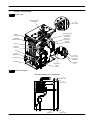
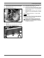
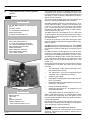
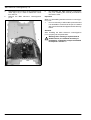
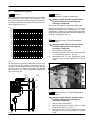
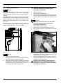
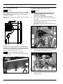
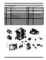
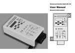
Wall hung, fan flue, room sealed, high efficiency gas boiler
Service manual
ActivA
Models:
G.C. Appl. No.
Activ A 12OV
Activ A 15OV
Activ A 20OV
Activ A 25OV
Leave this manual adjacent to the gas meter
Warning
Service / repairs must be carried out, only by a qualified Gas
Safety Registered Engineer, who will be responsible for the current Regulations for gas appliances.
Table of contents
1
1.1
1.2
Overall information . . . . . . . . . . . . . . . . . .
Overall View . . . . . . . . . . . . . . . . . . . . . . . . .
Hydraulic diagram . . . . . . . . . . . . . . . . . . . .
1
1
1
2
2.1
2.2
2.3
2.4
2.5
General access and emptying
hydraulic circuits . . . . . . . . . . . . . . . . . . . .
Nomenclature . . . . . . . . . . . . . . . . . . . . . . . .
Case panels . . . . . . . . . . . . . . . . . . . . . . . . .
Control panel . . . . . . . . . . . . . . . . . . . . . . . .
Main electronic p.c.b. box . . . . . . . . . . . . .
Emptying the primary circuit . . . . . . . . . . .
2
2
2
2
3
4
3
3.1
3.2
Diagrams . . . . . . . . . . . . . . . . . . . . . . . . . . .
Wiring diagram . . . . . . . . . . . . . . . . . . . . . . .
Circuit voltages . . . . . . . . . . . . . . . . . . . . . .
5
5
6
4
4.1
Fault finding . . . . . . . . . . . . . . . . . . . . . . . .
Display diagnostic . . . . . . . . . . . . . . . . . . . .
7
9
5
5.1
5.2
5.3
Condensing heat exchanger . . . . . . . . . .
Function . . . . . . . . . . . . . . . . . . . . . . . . . . . . .
Removal . . . . . . . . . . . . . . . . . . . . . . . . . . . .
Cleaning . . . . . . . . . . . . . . . . . . . . . . . . . . . .
10
10
10
11
6
6.1
6.2
6.3
6.4
6.5
6.6
6.7
Main electronic control/ignition p.c.b. .
Function . . . . . . . . . . . . . . . . . . . . . . . . . . . . .
Selection and adjustment devices . . . . . .
Checking the temperature . . . . . . . . . . . . .
Setting the boiler control function modes
Checks . . . . . . . . . . . . . . . . . . . . . . . . . . . . .
Removal of the electronic control p.c.b . .
Thermal control in the ”c.h.” mode . . . . .
12
12
12
13
13
15
15
17
7
7.1
7.2
7.3
7.4
7.5
Control panel electronic p.c.b. . . . . . . .
Function . . . . . . . . . . . . . . . . . . . . . . . . . . . . .
Normaly information . . . . . . . . . . . . . . . . . .
Info modality . . . . . . . . . . . . . . . . . . . . . . . . .
Function modes setting modality . . . . . . .
Removal of the control panel electr. p.c.b
18
18
18
19
19
19
8
8.1
8.2
8.3
8.4
8.5
Gas valve . . . . . . . . . . . . . . . . . . . . . . . . . . .
Function . . . . . . . . . . . . . . . . . . . . . . . . . . . . .
Description of the parts . . . . . . . . . . . . . . .
Adjustment . . . . . . . . . . . . . . . . . . . . . . . . . .
Checks . . . . . . . . . . . . . . . . . . . . . . . . . . . . .
Removal of the gas valve . . . . . . . . . . . . . .
21
21
21
21
23
23
9
9.1
9.2
9.3
9.4
Temperature probe . . . . . . . . . . . . . . . . . .
Function . . . . . . . . . . . . . . . . . . . . . . . . . . . . .
Checks . . . . . . . . . . . . . . . . . . . . . . . . . . . . .
Removal of the c.h flow temp. probe . . . .
Removal of the c.h. return temp. probe . .
25
25
25
25
25
10
10.1
10.2
Fan and Air box . . . . . . . . . . . . . . . . . . . . . 27
Function . . . . . . . . . . . . . . . . . . . . . . . . . . . . . 27
Removal of the Fan and the Air box . . . . . 27
11
11.3
11.4
Ignition and detection electrodes
and burner . . . . . . . . . . . . . . . . . . . . . . . . . .
Function . . . . . . . . . . . . . . . . . . . . . . . . . . . . .
Removal of the Ignition and detection
electrodes . . . . . . . . . . . . . . . . . . . . . . . . . . .
Removal of the burner . . . . . . . . . . . . . . . .
Checks . . . . . . . . . . . . . . . . . . . . . . . . . . . . .
12
12.1
12.2
12.3
Safety thermostat . . . . . . . . . . . . . . . . . . .
Function . . . . . . . . . . . . . . . . . . . . . . . . . . . . .
Checks . . . . . . . . . . . . . . . . . . . . . . . . . . . . .
Removal . . . . . . . . . . . . . . . . . . . . . . . . . . . .
30
30
30
30
13
13.1
13.2
13.3
Flue temperature probe NTC
and Safety thermal fuse . . . . . . . . . . . . . .
Function . . . . . . . . . . . . . . . . . . . . . . . . . . . . .
Removal . . . . . . . . . . . . . . . . . . . . . . . . . . . .
Checks . . . . . . . . . . . . . . . . . . . . . . . . . . . . .
31
31
31
31
14
14.1
14.2
14.3
Condensate trap . . . . . . . . . . . . . . . . . . . .
Function . . . . . . . . . . . . . . . . . . . . . . . . . . . . .
Check the cleanness of the trap . . . . . . . .
Removal . . . . . . . . . . . . . . . . . . . . . . . . . . . .
32
32
32
32
15
Short spare parts list . . . . . . . . . . . . . . . . 33
11.1
11.2
28
28
28
28
28
1
Overall information
1.1
Overall View
Flue temperature
probe NTC
C.h. flow
temp. probe
Safety
thermostat
Condensing heat
exchanger air
purger valve
Condensing
heat exchanger
Electronic
control box
Burner
Ighition
electrodes
Detection
electrode
Fan
Air box
(air/gas mixer)
C.h. return
temp. probe
Gas restrictor
C.h. pressure
relief valve
Gas valve
Condensate
trap
Pipe silencer
Control
panel
1.2
Hydraulic diagram
Central heating (c.h.) operation
C.h.
water flow
C.h.
water return
C.h.
water flow
C.h.
water return
1
2
General access and emptying
hydraulic circuits
2.1
Nomenclature
C
1
C
2
5
3
Fig. 2.3
To remove the side panels loosen the screws B
(Fig. 2.2) and C (Fig. 2.3).
4
Pull the side panels towards the outside.
To Fit the case panels
Fig. 2.1
Fit the side case panels
1
Right side panel
2
Main electronic p.c.b. box
Warning:
3
Front panel
4
Control panel
5
Left side panel
2.2
Fit the front panel hooking it on the upper side.
Push the front case panel until it is completely hold in
place (Fig. 2.4).
Ensure that the front panel edge is close---fitting to the
side panels.
Case panels
Lock in place the panel with the appropriate screws.
Warning: isolate the boiler from the mains
electricity supply before removing any
covering or component.
For the most part of the check and maintenance operations it is necessary to remove one or more panels of
the case.
The side panels can be removed only after the removal
of the front panel.
To remove the front panel loosen screws A (Fig. 2.2).
A
B
Fig. 2.4
2.3
B
Fig. 2.2 --- bottom view of the boiler
Pull the lower part of the front panel and lift it upwards
(Fig. 2.3).
2
Control panel
Warning: isolate the boiler from the mains
electricity supply before removing any
covering or component.
To gain access to the parts located inside the control
panel proceed as follows:
1
Remove the front panel of the case.
2
Unscrew the screw D (Fig. 2.5)
General access and emptying hydraulic circuits
3
Free the hooks indicated and rotate the lid towards left (Fig. 2.5).
E
Fig. 2.7
D
3
Slightly rotate the lid as indicated by the curved
arrow and free the rear hooks.
4
Remove the lid.
Main electronic p.c.b. lid removal
Fig. 2.5
4
To access to the parts located inside the control
panel turn it as shown in Fig. 2.6.
To get access to the main electronic p.c.b.:
5
Pull the box that contains the electronic p.c.b.
and rotate it (Fig. 2.8).
Fig. 2.6
2.4
Main electronic p.c.b. box
Warning: isolate the boiler from the mains
electricity supply before removing any
covering or component.
To gain access to the parts located into main electronic
p.c.b. box proceed as follows:
1
Remove the front panel of the case.
Terminal block lid removal
2
To remove the terminal block lid E (Fig. 2.7), free
the front hooks.
Fig. 2.8
6
Remove the terminal block lid E (Fig. 2.7).
7
Free the hooks placed on the three sides indicated and rotate the lid towards left (Fig. 2.9).
3
General access and emptying hydraulic circuits
4
To help the draining of the primary circuit loose
the condensing heat exchanger air purger valve
G (Fig. 2.11)
G
Fig. 2.9
2.5
1
2
3
Emptying the primary circuit
Close the c.h. circuit flow and return cocks.
Remove the front and right panels of the boiler.
Open the drain tap F (Fig. 2.10) until the boiler is
completely emptied.
Fig. 2.11
Attention: some water could remain in the condensing heat exchanger.
5
F
CLOSED
OPEN
Fig. 2.10
4
Close drain tap once the emptying has been
completed.
Diagrams
3.1
Wiring diagram
Gas valve
3
Condensate
trap
Fan
1
Ignition
electrodes
bu
bn
bu
gnye
M
~
bn
gnye
bu
bk
bu
wh
rd
4
Flame detection
electrode
gy
gy
3
gy
wh
wh
t
bk
C.h. return temp.
probe NTC
bk
wh
bu
gy
wh
bk
bu
wh
rd
wh
wh
gy
gy
wh
bn
rd
rd
bu
bk
t
bk
Flue temp.
probe NTC
bn
og
og
Fuse 2AF 250VAC
5x20
vt
bu
bu
bk
bk
bu
gnye
bu
t
bu
bk
bn
bk
C.h. flow temp.
probe NTC
Safety
thermostat
bk
bk
Time switch (option)
bk
Remote
External temp.
probe
terminal block
Electric supply
terminal block
Room thermostat
Pump
terminal block
bk
rd
rd
N
bu
gnye
L
bn
3
ye
2
og
1
wh
bn = brown
bu = blue
bk = black
wh = white
rd = red
gy = grey
vt
og
wh
ye
gn = green
ye = yellow
vt = violet
og = orange
gnye = green/yellow
rdwh = red/white
5
Diagrams
3.2
Circuit voltages
Electrical voltages with burner on
Gas valve
230~
0
230~
230~
230~
C.h. external
pump
during c.h. operation
Supply network
6
Fan
Safety
thermostat
7
TD
J
L3
J
J
Er 17
Er 18
J
J
J
J
J
J
J
J
J
J
J
J
---
5
Er 16
Er 15
--(4)
J
J
J
14.1
Er 14
J
Er 10
An 11
J
J
Er 09
Er 08
Er 06
Er 05
Er 04
Er 03
Er 02
Er 01
Defect
#
--(3)
--(2)
--(1)
Power supply line
Fault finding
Section of the manual !
(note ref. in brackets)
Appliance lock--- out (*)
Gas supply line
4
Disp
play indic
i catess ”Err”
Flue pipes
Cond. drain pipe and trap
C.h. circuit
External pump
Condensing heat exchanger
Fuses (Electronic p.c.b.)
J
J
6.5
Main electronic p.c.b.
Boiler settings
J
8.4
7
Control panel electr. p.c.b.
J
J
9.2
J
J
J
J
J
10
Components to check
Gas valve
C.h. flow temp. probe
C.h. return temp. probe
Fan / air restrictor
Ignition electrode
J
J
11.4
Detection electrode
12.2 12.2 13.1
J
Safety thermostat
Gas restrictor
J
J
Flue temp. probe NTC
--(7)
Expansion vessel external
J
J
---
J
---
External temp. probe
Pressure gauge external
---
J
---
Room themostat delayed
Safety valve external
Water leaks from the safety valve when the
boiler is off.
---
J
J
Power supply line
J
--(2)
Gas supply line
1
Check for 230V~ between line (L) and neutral (N)
Useful information can be obtained also from the
optical indication given by the appliance display
(see section 4.1).
Note
* Lock out is indicated as “Er” on the display.
Water leaks from the safety valve during
operation on c/h
---
Noisy bolier
Incorrect modulation
The boiler does not start.
The control panel display OFF
Fan still.
Defect
#
--(3)
Flue pipes
--(1)
4
2
3
--(4)
C.h. circuit
Fuses (Electronic p.c.b.)
J
6.5
Main electronic p.c.b.
J
J
J
Control panel electr. p.c.b.
J
8.4
C.h. flow temp. probe
J
J
J
J
10
Detection electrode
Ignition electrode
J
J
J
J
J
J
J
---
---
---
---
8
The boiler doesn’t reach the nominal heat input.
Check the pressurization of the expansion vessel. Refer to the
installation manual for proper values.
7
A jammed by--- pass could cause the over--- heating of the main
circuit and the intervention of the safety thermostat.
Safety thermostat
Cond. drain pipe and trap
--(7)
Safety valve external
Using the flue analyzer, check the CO2 value of the flue gases.
This reading is a reference value for the gas valve setting.
J
12.2 12.2 13.1
Pressure gauge external
6
5
Fan / air restrictor
J
11.4
Gas restrictor
9.2
External temp. probe
Components to check
Gas valve
7
C.h. return temp. probe
Boiler settings
Verify the integrity of supply cable, plug and external fuses.
Check the polarity of line and neutral connection
Check the gas supply pipe and isolation tap for gas tightness.
Check for soundness and absence of obstructions. Verify that
the flue terminal is correctly installed (see clearances) and ensure that exhaust gas is not sucked back by the boiler.
Check for soundness of the circuit and verify its correct filling
(see also installation manual).
J
Condensing heat exchanger
J
---
External pump
5
Flue temp. probe NTC
14.1
Expansion vessel external
Section of the manual !
(note ref. in brackets)
Appliance lock--- out (*)
No ”Er” iindication
on on display
Room themostat delayed
8
4.1
Display diagnostic
The display indications provide help in the diagnosis of
fault finding.
The control panel display gives other information for the
user.
The following table gives fault code, error and the reson
for the fault.
Er 01 + RESET Lack of burner ignition
Er 02 + RESET Safety thermostat lockout
Er 03 + RESET Other faults
Er 04 +
Faulty primary circuit (no water or
absence of flow)
Er 05 +
Faulty fan control system
Er 06 +
Faulty c.h. temperature probe
NTC
Er 08 +
Faulty external temperature probe
NTC (if fitted)
Er 09 +
Faulty flue temperature probe
NTC
Er 10 + RESET
Lockout --- flue temperature probe
NTC (Flue temperature > 120 ˚C)
Faulty pump (absence of water
Er 14 + RESET flow in the main circuit) or primary
temperature above 105 ˚C
None or too low water flow; Faulty
Er 15 + RESET pump (temp. difference between
probes higher than 35˚ C)
Possible exchange of NTC probes
Er 16 + RESET (Flow or Return) or pump wrongly
mounted (upside --- down)
Er 17 + RESET
Faulty c.h. temperature probe
NTC (Flow or Return)
Er 18 + RESET
Faulty primary circuit (no water or
absence of flow)
L3
Useful output limitation (temperature difference between probes
higher than 25˚ C) : Boiler test
performing
Td
Thermostat Delayed : Boiler test
performing
An 11
Parasite flame
9
5
Condensing heat exchanger
5.1
Function
N
K
The Condensing heat exchanger A in Fig. 5.1 has the
function of transferring heat produced from combustion of the gas and from the flue exhausted gas to the
water circulating in it.
Y
Y
J
S
I
A
H
N
L
X
C
F
G
E
B
F
Fig. 5.1
Fig. 5.2
By reducing the combustion products temperature, the
latent heat of the vapour is transferred to the water circuit, allowing an extra gain of useful heat.
13
Disconnect the fan connector M by pressing the
plastic hook placed on the side of the connector
(Fig. 5.4).
The condensed vapour is then drained through the
condensate trap B and the draining pipe C.
5.2
Removal
Warning: isolate the boiler from the mains
electricity supply before removing any
covering or component.
1
2
3
4
5
6
7
8
9
10
11
12
10
Turn off the gas supply.
Remove all the case panels (see section 2).
Disconnect the flue system from the boiler.
Disconnect the air manifold D (Fig. 5.4) by pulling
it.
Disconnect the rubber pipe E (Fig. 5.2).
Unscrew the gas connectors F.
Remove gas pipe G .
Unscrew the screws and remove the detection
electrode connector H.
Unscrew the screws and remove the ignition electrodes connector I .
Unscrew the screw and remove the overheat
thermostat J .
Disconnect the connector K by pressing the plastic hook placed on the side of the connector.
Disconnect the connector L
P
O
Fig. 5.3
14
15
16
Empty the primary circuit of the boiler.
Remove the forks N (Fig. 5.2).
Loosen the connection O and remove the pipe P
(Fig. 5.3) from the Condensing heat exchanger.
Condensing heat exchanger
17
18
19
Loosen the connection Q and remove the pipe R
(Fig. 5.4) from the Condensing heat exchanger.
Unscrew the screws S .
Remove the fan---burner group.
V
22
23
24
25
Q
M
X
R
W
D
Loosen the screws X (Fig. 5.4 --- Fig. 5.2)
Unscrew the screws Y (Fig. 5.2).
Remove the Condensing heat exchanger slightly
move it upwards, turn it frontwards freeing it from
the below screws X (Fig. 5.4 --- Fig. 5.2) and then
extract it forwards.
Reassemble the Condensing heat exchanger
carrying out the removal operations in reverse
order.
Ensure to tighten the screws S --- Fig. 5.2 firmly
5.3
Cleaning
If there are deposits of dirt between the fins of the Condensing heat exchanger, clean with a bristle paintbrush
and remove the dust with a hoover.
Warning: After cleaning or replacement as
detailed above, it is deemed necessary to
undertake a combustion analysis as detailed
in chapter 8.3 section 11.
Fig. 5.4
20
21
Unscrew the screws T and remove the plate U
(Fig. 5.5).
Remove the forks V and remove the condensate
trap W moving it downwards (Fig. 5.4).
U
T
Fig. 5.5
11
6
Main electronic control/ignition
p.c.b.
6.1
Function
Inlet Information
On the Main electronic control/ignition
p.c.b.......
Function control
C.h. temperature adjustment
Boiler reset button
(printed circuit board p.c.b.)
From other boiler devices....
C.h. flow temperature probe NTC
C.h. return temperature probe NTC
Flue temperature probe NTC
Safety thermostat
Flame detection electrode
Room thermostat (if fitted)
Time switch (if fitted)
Outlet command
External Pump
Gas valve
Fan
Ignition electrodes
Display indicates “Er”*
*control panel electronic p.c.b.
The fundamental function of the Main electronic control/ignition p.c.b. is that of controlling the boiler in relation to the external needs (i.e. heating the dwelling) and
operating in order to keep the temperature of the hydraulic circuits constant.
This is obviously possible within the useful power and
maximum working temperature limits foreseen.
Generally, the Main electronic control/ignition p.c.b. receives inlet information coming from the boiler (the
sensors) or from the outside (printed circuit board
p.c.b., room thermostat, etc.), processes it and consequently acts with outlet commands on other components of the boiler (Fig. 6.1).
The Main electronic control/ignition p.c.b. is also a full
sequence ignition device and does a sequence of operations (ignition cycle) which lead to the ignition of the
gas at the burner
It checks the presence of the flame during the entire
period in which it is activated and supplies the fan regulating its speed.
The Main electronic control/ignition p.c.b. has a safety
function and any incorrect interventions or tampering
can result in conditions of dangerous functioning of the
boiler.
The Main electronic control/ignition p.c.b. can lock the
functioning of the boiler (lock state) and stop its functioning up to the resetting intervention. The lock ---out is
signalled on the display of the control panel electronic
p.c.b. and can be reset only by using the boiler reset
button placed on the printed circuit board p.c.b. (see
section 7.1).
Some components which are connected to the device
can activate the lock state. The causes of a lock state
could be:
f
The intervention of the safety thermostat (overheat of the primary circuit).
f
The intervention of the flue temperature probe
(overheat of the combustion products).
f
A fault on gas supply.
f
Faulty ignition (faulty ignition electrodes, their wiring or connection).
f
Faulty flame detection (faulty detection electrode,
its wiring or connection).
f
Faulty condensate drainage.
f
Faulty gas valve (faulty on---off operators or not
electrically supplied).
f
Faulty Main electronic control/ignition p.c.b..
Other components like the c.h. temperature probes
NTC switch can temporarily stop the ignition of the
burner but allow its ignition when the cause of the intervention has stopped.
NO TAG and Fig. 6.12 show the sequence of the operations that are carried out at the start of every ignition
cycle and during normal functioning.
6.2
Fig. 6.1
12
Selection and adjustment devices
On the Main electronic control/ignition p.c.b. several
selection, adjustment and protection devices are located. (Fig. 6.2).
Main electronic control/ignition p.c.b.
Some of these devices are directly accessible by the
user (function control, temperature adjustment etc.)
others, like the fuses, are accessible by removing the
main electronic p.c.b. lid.
1
2
3
4
5
During the c.h. operation (Fig. 6.3), the signal coming
from the c.h. temperature probe is compared to the signal given by the control panel p.c.b. through the adjustment made by the user (key
). The result of
such a comparison operates the fan speed thus regulating the gas flow rate and consequently changing the
useful output of the boiler.
6
13
12
7
11
8
10
9
Fig. 6.2
1
Connector --- ignition electrode.
2
Connector --- flame detection electrode.
3
Connector --- controler fan.
4
Connector ---c.h. return temperature probe NTC
5
Connector --- flue temperature probe NTC.
6
Connector --- external temperature probe (optional).
7
Connector --- safety thermostat and c.h. flow temperature probe NTC.
8
Connector --- remote control (optional).
9
Connector --- display and function control / c.h.
temperature adjustment control panel p.c.b.
Fig. 6.3
10
Fuse F1, F2 2A F
11
Connector --- electric supply Main electronic control/ignition p.c.b.
12
Connector --- electric supply control panel p.c.b.
6.4
13
Connector --- gas valve, external pump and fan.
It is possible to select the various boiler control function
modes hereafter named “parameters” by using the
keys of the control panel p.c.b.
6.3
Checking the temperature
The control sequences in c.h. function are illustrated in
detail in section 6.7.
Setting the boiler control function modes
The Main electronic control/ignition p.c.b. makes it
possible adjust the c.h. water flow temperature.
A
The temperature of the water is converted into an electric signal by means of temperature probes.
The user, setting the desired temperature with the control panel p.c.b. key
If the power requested is lower than 40% of the maximum power output then control is achieved by switching ON the burner at minimum power, then switching
OFF (ON/OFF function). If the power requested is
higher, then the burner is switched ON at maximum
power and will control by modulating to 40% of the
maximum power output.
B
C
Fig. 6.4
1
To enter in the parameters setting mode press
contemporary the 3 keys (A --- B --- C Fig. 6.4) for
10 second until the display shows Fig. 6.5
13
Main electronic control/ignition p.c.b.
B
Fig. 6.9
7
Fig. 6.5
2
To exit for setting without modifing the set press
the keys (B --- C Fig. 6.10)
To move through the parameters press c.h. set
keys (A or C Fig. 6.6)
B
A
C
C
Fig. 6.10
To reset the boiler to the normal operation press contemporary the 3 keys (A --- B --- C Fig. 6.4) for 10 second.
Fig. 6.6
3
The display shows Fig. 6.7
The following table gives details of each parameter and
the possible value that can be set.
Important: at the end of the setting operation it is important to fill/update the table in the installation
manual see chapter COMMISSIONING section: Setting record.
PARAMETER
DIGIT VALUES
Boiler type (to be up- Pr 01
dated with the complete range)
00 = No power Er 99
18 = Activ A 12OV
19 = Activ A 15OV
20 = Activ A 20OV
21 = Activ A 25OV
Not used
Pr 02
Fig. 6.7
Not used
Pr 03
4
Not used
Pr 04
Gas type
Pr 05
A
Not used
Pr 06
B
C.h. flow max
temperature ˚C
Pr 07
85 ÷ 45 (factory set
85 ˚C)
Factory parameters Pr 08
reset
00 = No reset
04 = All parameters
return to factory set
with the exclusion of
Pr 01 and Pr 05
39 = All parameters
return to factory set
included Pr 01
and Pr 05
To modify the parameter press contemporary the
keys (A --- B Fig. 6.8)
Fig. 6.8
5
To change the parameters press c.h. set keys (A
or C Fig. 6.6)
6
To memorize the setting press the key (B Fig. 6.9)
14
00 = G20 Natural
05 = G31 Propane
Main electronic control/ignition p.c.b.
PARAMETER
Chimney
function
DIGIT VALUES
sweep Pr 09
00 = No chimney
sweep fun (factory
set)
01 = Low power
sweep---test
04 = C.h. power
sweep---test
07 = D.h.w. power
sweep---test
C.h. reignition fre- Pr 10
quency
00 ÷ 99 (0÷600 sec.)
(factory set 30 = 3
minutes)
C.h. pump post ---cir- Pr 11
culation
00 ÷ 99 (0÷600 sec.)
(factory set 10 = 1
minute)
Max. useful output in Pr 12
c.h. mode
00 ÷ 99 (0÷100%)
factory set:
99 = Activ A 12OV
99 = Activ A 15OV
99 = Activ A 20OV
99 = Activ A 25OV
C.h. pump working Pr 13
type
Ignition power
Pr 14
NTC on the c.h. re- Pr 18
turn
Pr 19
Not used
Pr 20
Not used
Pr 21
Not used
Pr 22
Not used
Pr 23
Not used
Pr 24
Not used
Pr 25
Not used
Pr 26
C.h. minimum set- Pr 27
point
25 ÷ 45 (factory set
25 ˚C)
Tab. 6.1
6.5
n
Checks
Check that the fuses are complete
If the Main electronic control/ignition p.c.b. does not
supply any device (pump, fan, etc.) check that the
fuses 10 (Fig. 6.2) are complete.
00 ÷ 99 (0÷100%)
factory set:
Start the boiler until the burner is ignited.
01 (=0,1)÷60 (=6,0)
K value
factory set:
00 = Off
Pr 16
D.h.w. burner turn off Pr 17
function
Not used
If a fuse has blown replace it with one that has the same
characteristics after having identified the reason for failure.
Propane (G31)
40 = Activ A 12OV
40 = Activ A 15OV
40 = Activ A 20OV
40 = Activ A 25OV
Not used
DIGIT VALUES
00 = Depends on
room
thermostat
(factory set)
04 = Always running
Natural gas (G20)
30 = Activ A 12OV
30 = Activ A 15OV
30 = Activ A 20OV
40 = Activ A 25OV
K value (external Pr 15
probe diagram)
PARAMETER
00 = Burner off at
fixed d.h.w. = 65 ˚C
(factory set)
01 = Brurner off at
set point +5 ˚C
00 = Probe not present
(factory set)
01 = Probe present
n
Lock sequence
With the burner firing, interrupt the gas supply. The
Main electronic control/ignition p.c.b. must carry out
four complete ignition cycles and then, after about 4
minutes, goes to lock ---out state.
Switch off and on the electricity supply to the boiler, by
means of the fused spur isolation switch, the device
must not unlock and the burner must not turn on
6.6
Removal of the electronic control p.c.b
Warning: isolate the boiler from the mains
electricity supply before removing any
covering or component.
When replacing the Main electronic control/ignition
p.c.b. all parameters must be correctly checked /
adjusted accordingly with the values noted in table
in the installation manual see chapter COMMISSIONING section: Setting record (for information on
parameters see also section 6.4).
1
Remove all the body panels (see section 2.2).
2
Gain access to the parts located inside the Main
electronic p.c.b. box as explained in the section
3
2.4 of this manual.
Remove all the wiring connected to the Main electronic control/ignition p.c.b..
15
Main electronic control/ignition p.c.b.
4
5
Delicately flex the hooks D in the directions indicated (Fig. 6.11) in order to release the circuit
from the box.
Remove the Main electronic control/ignition
p.c.b..
6
Re---assemble the Main electronic control/ignition p.c.b. following the removal procedures in
the reverse order.
Important
When re---assembling the Main electronic control/ignition p.c.b.:
7
It is not necessary to utilise static protections but
it is advisable to ensure that the pcb is handled
with care and held at the edges and with clean dry
hands.
Attention
After installing the Main electronic control/ignition
p.c.b. properly set the parameters.
D
Fig. 6.11
16
D
Warning: After cleaning or replacement as
detailed above, it is deemed necessary to
undertake a combustion analysis as detailed
in chapter 8.3 section 11.
Main electronic control/ignition p.c.b.
6.7
Thermal control in the ”c.h.” mode
Switch in the c.h. function mode
circulator off
fan still
Request for heat from
room thermostat?
NO
circulator on
YES
Is primary circuit
temperature higher than that
selected?
YES
Temp. difference
between probes
higher than 35˚ C ?
NO
YES
stop circulator (3min)
NO
YES
NO
lock memorised?
cancels lock
starts fan
checks fan rpm
Is fan rpm
exact?
NO
YES
Is flue
temperature higher than 110˚C?
NO
YES
beginning of wait period
flame presence?
End of wait
period?
YES
starts ignition discharges
Opens gas valve
beginning of ignition period
YES
NO
flame presence?
interrupts ignition discharges
gas valve open
fan runs
YES
NO
NO
End of ignition
period?
YES
closes gas valve
stops fan
interrupts ignition discharges
memorizes lock
display show lock--- out
NO
Is fan rpm
exact?
NO
NO
YES
safety thermostat or flue
temperature probe lock out?
YES
reset key
pressed?
flame presence?
YES
NO
YES
Fig. 6.12
17
7
Control panel electronic p.c.b.
LCD
FUNCTION
7.1
Function
Er 17 + RESET
Faulty c.h. temp. probe NTC
(Flow or Return)
Er 18 + RESET
Faulty primary circuit (no water or
absence of flow)
Er 04 +
Faulty primary circuit (no water or
absence of flow)
Er 05 +
Faulty fan control system
Er 06 +
Faulty c.h. temp. probe NTC
Er 08 +
Faulty external temp. probe NTC
Er 09 +
Faulty flue temp. probe NTC
D
A
B
C
Fig. 7.1
A) C.h. temperature increase key
B) C.h. temperature reduce key
C) Reset/Stand---by/Winter/Summer key
D) Display
The Control panel electronic p.c.b. can give to the service 3 levels of informations:
f
Normally information
f
Info modality
f
Function modes setting modality
7.2
Normaly information
KEY
RESET
The symbol indicates that the boiler
can be directly reactivated by the user,
by pressing the reset button.
Boiler Stand---By (anti---freeze
protection activaded)
Boiler waiting for heat request.
Boiler in winter mode.
The primary circuit temperature is
displayed.
Boiler on demand for c.h. power.
The symbol indicates that the fault requires intervention on behalf of specialised technical assistance.
Burner ignition (spark)
All symbols represented with lines that
surround them, indicate that the symbol is flashing.
Flame present (Burner on)
SIGNAL DISPLAYED BY THE LCD
LCD
FUNCTION
Er 01 + RESET
Lack of burner ignition on safety
lockout
Er 02 + RESET
Safety thermostat intervention
lockout
Boiler in anti---freeze phase (bP
flasching + temperature flashing)
Boiler in antifrost phase (AF
flasching + temperature flashing)
Er 03 + RESET General lockout
Er 10 + RESET Flue probe interven lockout
Er 14 + RESET
Faulty pump or primary temperature above 105˚ C
None or too low water flow; Faulty
Er 15 + RESET pump (temp. difference between
probes higher than 35˚ C)
Possible exchange of NTC probes
Er 16 + RESET (Flow or Return) or pump wrongly
mounted (upside --- down)
18
Set c.h.
(all other symbols are disabled)
Pump activated for the post ---circulation phase (Po flashing +
temperature flashing)
Control panel electronic p.c.b.
LCD
FUNCTION
Description
Parameter
Value
Delayed burner ignition for setting
the system (uu flashing + temperature flashing)
External temperature ˚C
(if fitted)
d1
-- 5
K value (external probe dia- d2
gram) (the value is x 10)
12
Boiler in chimney sweep functioning mode.
The chimney sweep is activated
by setting “parameter 09=01”
and is visualised by the switching
on of the hand and alternate
flashing between the tempereture
and the communication and radiator symbol.
Offset (Transaltion of K diagram d3
± 15˚C)
-- 10
C.h. temperature ˚C (calcu- d4
lated by external sensor)
66
C.h. flow temperature ˚C
d5
78
C.h. return temperature ˚C
d6
44
Flue temperature ˚C
d8
67
Thermostat Delayed:
Boiler test performing.
Fan speedy (the value has to d9
be x 100 = 4400 rpm)
44
SW version BC (burner control) dc
01
dd
03
Useful output limitation (temp. difference between probes higher
than 25˚ C):
Boiler test performing.
Flame detection error (An flasching + error flashing number)
7.3
Info modality
The INFO mode allows the display of some information
on the boiler functioning status. In case of malfunctioning of the boiler, it may be useful to communicate such
information to the Authorised Service Centre Engineer
so that the causes can be understood.
In order to access the INFO mode, press keys A and C
(Fig. 7.1) at the same time until the letter di appears on
the display that alternates with a code (Fig. 7.2).
SW version MB (main board)
Tab. 7.1
7.4
Function modes setting modality
It is possible to select the various boiler control function
modes hereafter named “parameters” by using the
keys of the control panel p.c.b.
During the function modes setting, the boiler does not
operate.
To get in function modes setting modality see section
6.4
7.5
Removal of the control panel electronic
p.c.b
Warning: isolate the boiler from the mains
electricity supply before removing any
covering or component.
1
2
3
Remove all the body panels (see section 2.2).
Gain access to the parts located inside the Control panel electronic p.c.b. as explained in the
section 2.3 of this manual.
Remove all the wiring A connected to the Control
panel electronic p.c.b. (Fig. 7.3).
Fig. 7.2
To scroll the values press B (reduce) and A (increase).
keys (Fig. 7.1). In order to exit the INFO mode, hold
keys A and C (Fig. 7.1) pressed at the same time.
The following table gives details of each parameter and
the possible value that can be show.
19
Control panel electronic p.c.b.
4
5
6
7
C
C
B
A
A
B
C
Fig. 7.3
20
Unscrew the screws B
Delicately flex the hooks C in the directions indicated (Fig. 7.3) in order to release the circuit from
the box.
Remove the Control panel electronic p.c.b..
Reassemble the Control panel electronic p.c.b.
carrying out the removal operations in the reverse
order.
8
Gas valve
8.1
Function
The Gas valve A in Fig. 8.1 controls the gas inflow to the
boiler burner.
1
2
3
Maximum gas pressure adjustment
Minimum gas pressure adjustment
On---off operators
4
5
On---off operators electric connector
Gas valve inlet pressure test point
8.3
Adjustment
Warning: isolate the boiler from the mains
electricity supply before removing any
covering or component.
Check the supply pressure before making any adjustment to the gas valve.
1
Close the gas inlet valve.
2
Remove the front panel of the case and lower the
control panel (see sections 2.2 and 2.3).
Loosen the internal screw on the Inlet Pressure
Test Point 5 (Fig. 8.2) of the Gas valve and connect a pressure gauge using a suitable hose.
3
A
4
5
Open the gas inlet valve.
Turn on the electricity supply to the boiler, switching on the fused spur isolation switch.
6
Set the boiler in c.h. function as illustrated in
Fig. 8.3
Fig. 8.1
C.h.
function
By means of an electric command given to the on---off
operators the passage of the gas through the Gas valve
can be opened or closed.
8.2
Description of the parts (Fig. 8.2)
Fig. 8.3
7
8
1
2
9
10
3
Disconnect the pressure gauge and close the
Inlet Pressure Test Point 5 (Fig. 8.2).
Gas valve adjustment
The person carrying out a combustion
measurement should have been assessed as
competent in the use of a flue gas analyser
and the interpretation of the results.
The flue gas analyser used should be one
meeting the requirements of BS7927 or
BS-- EN50379-- 3 and be calibrated in
accordance with the analyser manufacturers’
requirements, and have a current calibration
certificate.
4
5
11
Fig. 8.2
Make sure that the room thermostat is in the “heat
request” position.
Read the inlet pressure value and ensure that it is
within the limits given in the table Gas supply
pressures, of the user/installation manual
If it does not comply with the required pressure
check the gas supply line and governor for faults
and/or correct adjustment.
Switch off the boiler close the gas inlet valve.
Fit the probe of the flue analyser in the flue exhaust sampling point located on the exhaust
pipes of the boiler (Fig. 8.4).
21
Gas valve
flue
exhaust
sampling point
air intake
sampling point
Fig. 8.7
Fig. 8.4
12
Turn on the boiler, switching on the fused spur
isolation switch.
13
Open the gas inlet valve.
14
Turn on the boiler and operate for 2 minuets to
pre---heat the flue, before commencing any adjustments
A
B
C
17
Make sure that the room thermostat is in the “heat
request” position.
18
Allow the analyser to give a stable reading.
19
Read the CO2 % value.
It should be between:
Model
Type gas
CO2 % value
(range)
Activ A 12OV
A ti A 15OV
Activ
Natural (G20)
8,2 --- 9,0
Propane (G31)
9,2 --- 10,2
Activ A 20OV
A ti A 25OV
Activ
Natural (G20)
8,2 --- 9,2
Propane (G31)
9,2 --- 10,2
Tab. 8.1
Fig. 8.5
To adjust the CO2 % value remove the brass plug by unscrewing it and rotate the Allen key screw ø 4 mm (2 --Fig. 8.2) (by rotating it clockwise the CO2 % increases).
15
Checking the maximum gas valve setting
To enter in the parameters setting mode press
contemporary the 3 keys (A --- B --- C Fig. 8.5) for
10 second until the display shows Fig. 8.6
20
Press key A to vary the output in chimney sweep
mode: when the display shows the letters cP that
alternate with the heating water temperature
value (e.g.60), the ”chimney sweep function” is at
maximum output in heating mode (Fig. 8.8);
Fig. 8.6
Adjusting minimum gas valve setting
16
22
Press keys A and C (Fig. 8.5) at the same time
until the display shows the letters LP that alternate with the heating water temperature value
(e.g.45), indicating the activation of the ”chimney
sweep function” at minimum output (Fig. 8.7).
Fig. 8.8
21
Press further key A. The display shows the letters
dP that alternate with the heating water temperature value (e.g.60)(Fig. 8.9). On this models this
step is not relevant and the value shown is the
same of the step 20. No setting is needed on this
step.
Gas valve
ON---OFF Operator
approx. 6 400 Ω*
ON---OFF Operator
approx. 920 Ω*
* at ambient temperature.
Fig. 8.11
8.5
Warning: isolate the boiler from the mains
electricity supply before removing any
covering or component.
Fig. 8.9
22
Allow the analyser to give a stable reading.
23
Read the CO2 % value.
It should be between:
1
Model
Type gas
CO2 % value
(range)
Activ A 12OV
Activ
ct A 15OV
5O
Activ A 20OV
Activ A 25OV
Natural (G20)
8,9--- 9,8
Propane (G31)
9,9 --- 10,8
Removal of the gas valve
Remove the front panel of the case as explained
in the section 2.3 of this manual.
Disconnect the connector D (Fig. 8.12).
Unscrew the screws E and disconnect the earth
connector F.
2
3
Tab. 8.2
J
To adjust the CO2 % value rotate screw (1 --- Fig. 8.2)
(by rotating it clockwise the CO2 % decreases).
24
I
F
Press keys A --- B --- C (Fig. 8.5) at the same time
again to exit the ”chimney sweep mode” and return to the previously set boiler status (Fig. 8.10)
G
E
D
C.h.
function
I
H
Fig. 8.10
25
Switch off the boiler and turn off the room thermostat.
K
26
Close the air---flue sampling points.
27
After adjustment fit the protective brass plug (2,
Fig. 8.2).
4
Important: after the gas pressure checks and any
adjustment operations, all of the test points must be
sealed.
5
8.4
Checks
Warning: isolate the boiler from the mains
electricity supply before removing any
covering or component.
Fig. 8.12
6
7
8
Turn off the gas supply and disconnect the gas
isolation cock connector from the inlet port of the
gas valve.
Using pliers, remove the spring G and the rubber
pipe H (Fig. 8.12).
Unscrew the connectors I (Fig. 8.12) and remove
the pipe J .
Unscrew the screws K and remove the valve
(Fig. 8.12).
Reassemble the valve carrying out the removal
operations in reverse order.
n
Check the on---off operators coils
1
Remove the front panel of the case.
Before fitting a new valve, it is advisable to pre-- set
it as follows.
2
Disconnect the electrical connector 4 (Fig. 8.2).
9
3
Measure the electrical resistance between the
connector pins of the on---off operators as illustrated in Fig. 8.11.
10
Remove the brass plug and turn the plastic screw
inside it fully clockwise until it stops. Do not overtight.
Turn it counter---clockwise 2 and 3/4 turns.
23
Gas valve
11
Adjust the gas valve using the flue analyser as described in section 8.3.
After any service operation on the components of
the gas circuit check all the connections for gas
leaks.
Warning: After cleaning or replacement as
detailed above, it is deemed necessary to
undertake a combustion analysis as detailed
in chapter 8.3 section 11.
24
9
Temperature probe
9.1
Function
9.2
The Temperature probe has the function of converting
the temperature of the water in the hydraulic circuit
where it is installed into an electrical signal (resistance).
The relation between temperature and electrical resistance is stated in Fig. 9.1.
Ω 12500
n
Checks
Temperature---resistance relationship
Warning: isolate the boiler from the mains
electricity supply before removing any
covering or component.
Disconnect the cable from the Temperature probe.
Measure the temperature of the pipe C (c.h. flow Temperature probe)(Fig. 9.3) or of the pipe D (c.h. return
Temperature probe)(Fig. 9.4) where the Temperature
probe is located and check the electrical resistance according to the graph in Fig. 9.1.
12000
11500
11000
10500
10000
9500
9000
8500
8000
7500
7000
6500
6000
5500
5000
4500
4000
3500
3000
2500
2000
1500
1000
500
9.3
Removal of the c.h flow Temperature
probe
Warning: isolate the boiler from the mains
electricity supply before removing any
covering or component.
20 25 30 35 40 45 50 55 60 65 70 75 80 85 90 95 100
1
Remove all the case panels.
2
Remove the electric connector E and remove the
c.h. Temperature probe A --- Fig. 9.3
3
Reassemble the c.h. flow Temperature probe
carrying out the removal operations in reverse
order.
˚C
Fig. 9.1
On the boiler there are two Temperature probes. One
on the output of the primary condensing heat exchanger (c.h. flow Temperature probe) A in Fig. 9.2 and
Fig. 9.3; one on the inputof the primary condensing
heat exchanger (c.h. return Temperature probe) B in
Fig. 9.2 and Fig. 9.4.
c.h.
flow
E
c.h.
return
A
A
C
B
Fig. 9.3
9.4
Removal of the c.h. return Temperature
probe
Warning: isolate the boiler from the mains
electricity supply before removing any
covering or component.
Fig. 9.2
1
Remove all the case panels.
2
Remove the electric connector F and c.h. return
Temperature probe B --- Fig. 9.4
3
Reassemble the c.h. return Temperature probe
carrying out the removal operations in reverse
order.
25
Temperature probe
F
B
D
Fig. 9.4
26
10
Fan and Air box
10.1
Function
The function of the Fan A (Fig. 10.1) is to force the mixture of air and gas into the burner.
The function of the Air box B is to mix the gas and the
air in the right proportion.
The flow rate of the air---gas mixture and consequently
the input power of the boiler is proportional to the speed
of the fan that is controlled by the electronic control
p.c.b.
3
Disconnect the rubber pipe C (Fig. 10.2).
4
Unscrew the gas connectors D and remove the
gas pipe E.
5
Disconnect the connector F
6
Disconnect the fan connector G by pressing the
plastic hook placed on the side of the connector.
7
Unscrew the screws H.
8
Remove the fan A with the air box B.
9
Remove the screws I and the air box B (Fig. 10.3).
A
I
I
B
B
I
Fig. 10.3
10
Open the strip J by sliding the edges with the help
of a screwdriver and remove the Air box
Fig. 10.4.
J
Fig. 10.1
10.2
B
Removal of the Fan and the Air box
Warning: isolate the boiler from the mains
electricity supply before removing any
covering or component.
1
Turn off the gas supply.
2
Remove all the case panels (see section 2).
F
G
Fig. 10.4
E
11
D
H
A
Assemble the Fan and the Air box carrying out
the removal operations in reverse sequence.
Before reassembling ensure the
(Fig. 10.2) is correctly mounted.
fan gasket
After any service operation on the components of
the gas circuit check all the connections for gas
leaks.
C
Fig. 10.2
D
Fan gasket
Warning: After cleaning or replacement as
detailed above, it is deemed necessary to
undertake a combustion analysis as detailed
in chapter 8.3 section 11.
27
11
Ignition and detection electrodes
and burner
2
11.1
Function
3
Three electrodes are fitted on the fan---burner group.
Two of them, fitted on the right side of the fan---burner
group A, are the ignition electrodes B
4
On the left side is the detection electrode C and it detects the presence of the flame.
Disconnect the ignition electrodes connector E
and the earth wire F (Fig. 11.1) and disconnect
the detection electrode connector G.
Unscrew the screws H and remove the ignition
electrodes B and the detection electrode C
(Fig. 11.1).
Assemble the Ignition and detection electrodes
carrying out the removal operation in reverse order.
11.3
Removal of the burner
Warning: isolate the boiler from the mains
electricity supply before removing any
covering or component.
F
1
2
H
3
B
H
A
Remove the air box and the fan (see section 10.2)
Unscrew the screws I (Fig. 11.1 ) and remove the
fan---burner duct A.
Remove the burner by sliding it forward.
locating tab
I
H
C
E
G
Fig. 11.1
The burner D is fitted on the rear of the fan---burner
group A.
burner gasket
Fig. 11.3
4
Assemble the burner carrying out the removal
operation in reverse order. Ensure the burner is
correctly located by lining up the locating tab
(Fig. 11.3).
Before reassembling ensure the burner gasket is
correctly located.
Warning: After cleaning or replacement as
detailed above, it is deemed necessary to
undertake a combustion analysis as detailed
in chapter 8.3 section 11.
D
11.4
n
Fig. 11.2
11.2
1
28
Remove all the case panels (see section 2) .
Check the position of the electrode edges
Warning: isolate the boiler from the mains
electricity supply before removing any
covering or component.
Removal of the Ignition and detection
electrodes
Warning: isolate the boiler from the mains
electricity supply before removing any
covering or component.
Checks
1
2
Remove the ignition electrodes (see section 11.2)
Check for the correct distance between the metallic edges of the ignition electrode (see
Fig. 11.4).
Ignition and detection electrodes
earth electrode
n
Check the connection wires.
3,5 mm
Ignition electrode
Fig. 11.4
29
12
Safety thermostat
12.1
Function
The safety thermostat A in Fig. 12.1 is a device that
senses the temperature of the primary circuit water
which flows in the outlet pipe of the condensing heat exchanger.
If the temperature control system of the boiler fails and
the temperature of the primary circuit reaches a dangerous temperature, the safety thermostat opens the
electric circuit that supplies the on---off operators of the
gas valve.
Consequently, the full sequence ignition device attempts to light the burner and, at the end, locks the
boiler and lights the lock ---out on the display.
Warning: isolate the boiler from the mains
electricity supply before removing any
covering or component.
n
1
2
Electrical function
Remove all the case panels.
Disconnect the safety thermostat and check its
electrical function. Normally (no intervention) the
contact must be closed (electrical resistance zero
Ω).
12.3
Removal
Warning: isolate the boiler from the mains
electricity supply before removing any
covering or component.
1
2
3
A
Remove all the case panels.
Disconnect the wiring B (detail in Fig. 12.2).
Unscrew the screws C and remove the safety
thermostat.
B
C
Fig. 12.1
12.2
Fig. 12.2
Checks
n
Overheat temperature value
1
Run the boiler and set the temperature at maximum by pressing the appropriate key.
2
Allow the boiler to reach its maximum operating
temperature. The boiler should maintain a temperature below that of the safety thermostat and
no overheat intervention should occur.
30
4
5
Reassemble the safety thermostat carrying out
the operations in reverse order.
Apply an adequate quantity of heat conducting
compound between the condensing heat exchanger and the thermostat.
Warning: After cleaning or replacement as
detailed above, it is deemed necessary to
undertake a combustion analysis as detailed
in chapter 8.3 section 11.
13
13.1
Flue temperature probe NTC and
Safety thermal fuse
13.2
Warning: isolate the boiler from the mains
electricity supply before removing any
covering or component.
Function
The Flue temperature probe NTC A in Fig. 13.1 and
Fig. 13.2 senses the temperature of the combustion
products that flow through the condensing heat exchanger.
Removal
1
Remove all the case panels.
2
Disconnect the connector B from the Flue temperature probe NTC by pressing the plastic hook
placed on the side of the connector.
3
Unscrew and remove the flue temperature probe
A (Fig. 13.2) from the condensing heat exchanger.
4
Assemble the Flue temperature probe NTC carrying out the removal operations in reverse sequence.
A
13.3
Checks
n
Overheat temperature value
1
Run the boiler and set the temperature at maximum by pressing the appropriate key.
2
Allow the boiler to reach its maximum operating
temperature. The boiler should maintain a temperature below that of the Flue temperature
probe NTC and no overheat intervention should
occur.
Fig. 13.1
n
Temperature---resistance relationship
If the temperature of the combustion products circuit
reaches the limit temperature, the Flue temperature
probe NTC reduces the gas flow rate to the burner. The
temperature of the combustion products should decrease to a safe value temperature.
1
Remove the Flue temperature probe NTC (see
section 13.2).
2
Measure the Flue temperature probe NTC electrical resistance at the ambient temperature and
check it according to the graph in Fig. 13.3
In the case that the temperature of the combustion
products reaches a potentially dangerous value, it
stops the boiler operation (lock ---out).
This allows the use of plastic materials for the flue outlet
pipes and bends.
The use of kits different from the original isn’t however
allowed, since the flue pipes are integral parts of the
boiler.
A
B
Ω 12500
12000
11500
11000
10500
10000
9500
9000
8500
8000
7500
7000
6500
6000
5500
5000
4500
4000
3500
3000
2500
2000
1500
1000
500
20 25 30 35 40 45 50 55 60 65 70 75 80 85 90 95 100
Fig. 13.2
˚C
Fig. 13.3
31
14
Condensate trap
14.1
Function
Unscrew the plug D on the bottom of the trap A and remove dirt eventually deposit (Fig. 14.3).
The condensate trap A in Fig. 14.1 and Fig. 14.3 allows
the discharge of the condensate via the condensate
drain pipe avoiding in the mean time the escape of
combustion products.
A plastic ball closes the trap outlet in case that the trap
is empty.
14.3
Removal
Warning: isolate the boiler from the mains
electricity supply before removing any
covering or component.
1
2
Remove the front and right case panels.
Unscrew the screws B and remove the plate C
(Fig. 14.2)
Unscrew the threaded locking ring E and remove
the flexible pipe F (Fig. 14.3).
Disconnect the electric connector G (Fig. 14.3 --Fig. 14.4)
3
4
H
G
F
A
E
A
D
G
Fig. 14.1
If the drain pipe becomes blocked, or condensate cannot drain, the condensate level it the trap rises until it reaches the screw attached to the flame detection electrode, this will cause the boiler lock ---out.
14.2
1
Fig. 14.3
Remove the forks H and remove the condensate
trap A moving it downwards (Fig. 14.3).
5
Check the cleanness of the trap
Unscrew the screws B and remove the plate C
(Fig. 14.2).
G
C
B
Fig. 14.4
6
Fig. 14.2
32
Reassemble carrying out the removal operations
in reverse order.
15
Short spare parts list
Key G.C. part no.
Description
1
Burner (mod. Activ A 12OV, Activ A 15OV
Activ A 20OV)
2
Q.ty ManufacManufacturer’s reference
turer part no.
1
BI1313 100
Burner (mod. Activ A 25OV)
1
BI1313 101
Condensing heat exchanger
(mod. Activ A 12OV, Activ A 15OV, Activ A 20OV)
1
BI1462 101
Condensing heat exchanger (mod. Activ A 25OV)
1
BI1462 102
3
Fan
1
BI1313 102
4
Gas valve
1
BI1313 103
5
Main Electronic control/ignition p.c.b.
1
BI2035 113
6
Control panel electronic p.c.b.
1
BI2035 101
7
Temperature probe (main circuit)
1
BI1442 106
8
E83---101
Overheat thermostat
1
BI1172 105
9
H58---661
Flue temperature probe NTC
1
BI1432 102
10
E23---792
Fuse 2 AF 250VAC 5x20
2
BI1165 112
11
Detection electrode
1
BI1313 104
12
Ignition electrode
1
BI1313 105
13
Condensate trap
1
BI1462 104
SIT 848 Sigma 0848135
ELTH --- type 261
2
1
3
5
10
8
7
4
6
13
11
9
12
33
17962.2017.0
1710 36A4 UK
Biasi UK Ltd
Commercial Road
Leamore Enterprise Park
WALSALL
WS2 7NQ
Tel : 01922 714600
www.biasi.co.uk
N
29/04
2010
*1796220170*