1
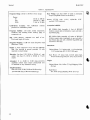
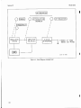
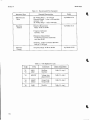
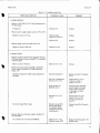
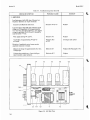
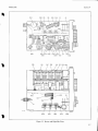
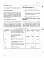
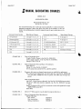
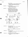
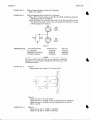
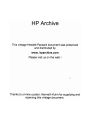
Model 201C
Section V
Table 5-5. Troubleshooting Chart (Cont’d)
POSSIBLE CAUSE
CHECK OR SYMPTOM
REMEDY
3. AMPLIFIER
Load instrument with 600 ohms. Measure low
frequency distortion at output terminals.
Defective V4 or VS
Replace
Weak signals driving V4 and V5
Defective V3
Replace
Amplitudes of signals driving V4 and V5
not equal.
Defective R21
or R22
Investigate and replace
Measure dc voltage for approximately 0.2 volts.
Voltage high.
Defective C9
Replace (See Paragraph 5-31).
Voltage above satisfactory. Control still produces unstable output variation.
Defective R17
Replace
Excessive 2nd Harmonic distortion.
Load instrument with 600 ohms. Measure signal
voltage on V3A grid (pin 5) for approximately
13 V rms when instrument delivers 1 watt. Signal
voltage on grids (pin 5) of V4 and V5 should be
approximately 5 V rms.
Rotation of amplitude control causes erratic
amplitude variation in output.
v4
v3
v5
V6
52
R25
Cll
s;
Ri7
d9
TI
Figure 5 4 . Left Side View
T2
c12