1
SUPER STAR
USER'S
tlll\NUAL
U.S.A
ADVANCED DIGITAL CORPORATION
5432 PRODUCTION DR.
HUNTINGTON BEACH, CA 92649
TELEX: 183210 ADVANCED
TEL: (714) 891-4004
EUROPE
ADVANCED DIGITAL (U.K) LTD.
27 PRINCESS STREET
HANOVER SQUARE
1..0NDON, WIR8NQ
UNITED KINGDOM
TELEX: 265840 FINEST
TEL: (81)409-9917
NOTICE
Advanced Digital does not assume any liability arising out ot
the application or use ot any products, circuit or sottware
described herein, neither does it convey any license under its
patent rights nor the patent rights ot others. Advanced Digital
tutther reserves the right to make changes to any products
described herein without notice. This document is also subject
to revision.
TABLE OF CONTENTS
Page
Section
SECTION 1 GENERAL INFORMATION
1 .1
1.2
1.3
1.4
1.5
Introduction
System Contigurations
Purpose ot Manual
How The Manual Is Organized
Related Documents
1-1
1-1
1-2
1-2
1-3
SECTION 2 SUPER STAR PHYSICAL DESCRIPTION
2.1
2.2
2.3
Maintrame Front Panel
Maintrame Internal Parts
Maintrame Rear Panel
2-1
2-2
2-3
SECTION 3 INTERFACE CONNECTORS
3 .1
3.2
3.2.1
3.2.2
3.2.3
3.3
3.4
3.5
Intertace Connectors Location
Serial 1/0 Port Connectors
Typical Three-wire Intertace
Four-wire Intertace
Serial Printer Intertace
Parallel 1/0 Port Connectors
I/O Port Contigurations
Internal Ribbon Cable Connectors
3-1
3-1
3-1
3-2
3-2
3-2
3-3
3-3
SECTION 4 SYSTEM SPECIFICATIONS
4.1
4.2
4.3
4.4
Introduction
System Power Requirements
Specitications
Changing AC Input Voltage trom
110/220 to 220/110
4-1
4-1
4-1
4-8
SECTION 5 INSTALLATION AND INITIALIZATION
5.1
5.2
5.3
5.4
5.5
Installation Procedure
Initial System power-Up
Copying The System Disk (1'urboDOS)
Copying The System Disk (CP/M 3.0)
Copying The System Disk (CP/M 2.2)
iii
5-1
5-6
5-7
5-10
5-13
TABLE OF CONTENTS (Continued)
Section
Page
SECTION 6 THE OPERATING SYSTEM
6.1
6.2
6.2.1
6.2.2
6.2.3
6.3
6.3.1
6.3.2
6.4
6.4.1
6.4.2
6.4.3
6.4.4
6.4.5
6.4.6
6.5
6.5.1
6.5.2
6.5.3
6.5.4
6.5.5
6.5.6
6.6
6.7
6.7.1
6.7.2
6.7.3
6.7.4
6.7.5
6.7.6
6.B
6.B.1
6.B.2
Introduction
Contiguring The SUPER STAR System
SUPER STAR CP/M Hardware Contiguration
SUPER STAR TurboDOS Hardware Contiguration
He1ptu1 Hints When Setting Up a
TurboDOS Multi-User System
. Basic Operating System Structure
CP/M
TurboDOS
Single User System (CP/M 2.2)
Copying Hard Disk to Diskettes
Copying Hard Disk to Cartridge
Copying Cartridge to Diskette
Copying Cartridge to Fixed Disk
Copying Diskettes to Fixed Disk
Copying Diskettes to Cartridge
Single User System (CP/M 3.0)
Copying Fixed Disk to Diskette
Copying Fixed Disk to Cartridge
Copying Cartridge to Diskette
Copying Cartridge to Fixed Disk
Copying Diskettes to Fixed Disk
Copying Diskettes to Cartridge
Setting Real Time Clock
Multi-User System (TurboDOS)
Copying Fixed Disk to Diskettes
Copying Fixed Disk to Cartridge
Copying Cartridge to Diskette
Copying Cartridge to Fixed Disk
Copying Diskettes to Fixed Disk
Copying Diskettes to Cartridge
Error Message Summary
CP/M
TurboDOS
6-1
6-1
6-1
6-2
6-3
6-4
6-5
6-5
6-5
6-5
6-7
6-8
6-9
6-11
6-12
6-13
6-13
6-15
6-15
6-17
6-17
6-1B
6-20
6-20
6-20
6-21
6-22
6-23
6-23
6-24
6-25
6-26
6-26
SECTION 7 LIST OF RECOMMENDED PERIPHERALS AND SOFTWARE
7.1
7.2
Recommended Peripherals
Recommended Sottware
iv
7-1
7-1
TABLE OF CONTENTS (Continued)
Section
Page
SECTION 8 PROBLEN ISOLATION
8.1
8.2
8'.3
Introduction
The First Step
Isolating A Hardware Problem
8-1
8-1
8-1
SECTION 9 BaST TO SUPER STAR COMMUNICATIONS
9.1
Introduction
9.1
SECTION 11 CP/M AND TURBODOS SOFTWARE DIRECTORIES
10.1
10.2
10.3
10.4
Introduction
CP/M 2.2 Directory
CP/M 3.0 Directory
TurboDOS Directory
v
10-1
10-1
10-1
10-1
TABl.E OF CONTENTS (Continued)
APPENDICES
Page
A
A.l
A.2
B
C
D
E
E.l
E.2
E.3
E.4
F
G
Care and Handling at Diskettes and cartridge Disks
Dis k e t. t f: ~;
A-1
Cartridge Disks
A-2
B-1
ASCII
warranty
C-1
System Contigur~tion
D-1
Internal Ribbon and Power Cable Connections
Intrortuctjon
E-1
Internal Ribbon Cables
E-l
E-4
Internal Cable COllncctor Pin Assignments
Power SupJ?ly
E-6
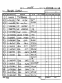
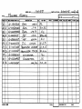
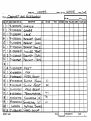
SUPER STAR Parts List
E-l
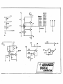
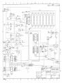
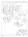
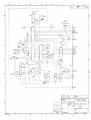
System Schematics
G-1
LIST OF ILLUSTRATIONS
f
P;;ge
19nre
2-1
2-2
2-3
A-I
1\-2
E-1
E-2
SUPER S'l'l\R Front Panel
SUPER STAR Internal Section
SUPSR STAR Rear Panel
Floppy Diskettes
Cartridqe Disks
Internal RilJbon Cables
SUPER STAR Power Supply Schematic Diagram
2-1
2-2
2-3
A-J
1\-2
£-1
E-4
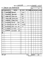
LIST OF TABLES
Table
3-1
3-2
4-1
4-2
4-3
4-4
4-5
4-6
Page
Serial I/O Port Pin Assign~ents
Parallel 1/0 Port Pin Asslgnm8nts
SUPER QUAD CPU Module
SlIPER SIX CPU Module
Hard Disk Drive and Controller Subsy~tem
Flnupy Disk Drive
SUP EnS 1.1\ 'n.; r'lO c1 u 1 e
SUP E R SLAV E Ov era 11 S pe cit i cat i
vi
CH J S
3-1
3-2
4-1.
4- 3
4-4
4-5
4-6
4-7
TABLE OF CONTENTS (Continued)
LIST OF TABLES (Continued)
Page
Table
6-1
6-2
E-l
E-2
E-3
E-4
SUPER SLAVE Switch Sl Address Setting
USERID. SYS File Layout
5-100 Bus Motherboard Pin Assignments
CPU Board Ribbon Cable Connector Pin
Assignments
DMA Board Ribbon Cable Connector Pin
Assignments
Power Supply Connector's Pin Assignments
vii
6-2
6-2
E-2
E-3
E-3
E-3
SECTION 1
GENERAL INFORMATION
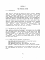
1.1
Introduction
The Advanced Digital SUPER STAR is the most advanced 8-bit or 16bit, 5-100 bus-based single user/stand-alone and IDulti-user/multiprocessing computer system in today's marketplace tor business,
protessional and educational applications.
When contigured as a
single-user, stand-alone system, the CP/M Operating S'ystem allows
access to a vast library ot ap~lication sottware packaqcs.
Add
the TurboDOS Operating System and trom one to tour StTpt;:R Sl.AnE
modules and the SUPER STAR becomes a multi-task networking system
tor
up to twelve users. With either contiguration, SUPER STAR
otters the tollowing teatures:
- 10 Mbyte 5 l/4h ~inchestcr Hard Disk Drive
5Mbyte tixed and 5Mbyte removable cartridge)
- Separate Hard Disk Controller module tor high
speed data transter
- 5 1/4", Halt-high, 48 TPI Floppy Disk Drive
Six-slot, 5-100 Bus compatible motherboard
- 4 MHz, Z80A CPU, Floppy Disk Controller,
64 Kbyte RAM, 2K
(or optional 4K ) monitor EPROM,
Optional Z80B PIO and SIO SUPER SIX with optional
1?8 Kbyte RAM
- Contigurable tor up to tive users using SUPER SLAVE
modules with TurboDOS or as a single-user st0nd-alone
systpm with CP/M 2.2/3.0 or TurboDOS
- Slim-line, selt-contained cabinet
1.2 System Contigurations
Single User Systems
-SUPER QUAD or SUPER SIX (optional)
-4R TPI Floppy Dibk Drive
-10 Mb Hard Disk w/Controller
5Mb removablp-/5 Mb Fixed
-CP/M 2.2 or CP/M 3.0
-TurboDOS
1-1
General Intormation
Multi-user System
-SUPER QUAD or SUPER SIX (optional)
-One SUPER SLAVE (4 MHz or 6 MHz)
-48 TPI Floppy Disk Drive
-10 Mb Hard Disk w/Controller
5Mb removable/5Mb tixed
-TurboDOS
1.3 Purpose ot Manual
This manual has been designed to supply the intorrnation needed by
the stand-alone or multi-tasking user to install, contigure and
operate the SUPER STAR.
Intormation
is also provided tor
identitying and then isolating the problem,
it it should occur,
to determine it the problem can be solved simply by the user or
it it must be retered to a qualitied service organization.
The
manual has been written at a system level (i.e.,
the complete
SUPER STAR)
and does not attempt to discuss specitic design
characteristics ot individual modules or the operating system
sottware within the system.
That intor~ation is contained
in
individual manuals also supplied with the SUPER STAR system.
1.4 Bow The Manual Is Organized
This manual is organized into seven sections and tive Appendices.
The subjects covered by each section and appendix are listed
below:
Section
1,
Section
2,
Section
3,
Section
4,
Section
5,
Section
6,
Section
7,
Section
8,
General Intormation - Intormation to the SUPER
STAR and this manual.
SUPER STAR Physical Description - Explanation
ot the tront panel, rear panel and internal
layout.
Intertace Connectors - Description ot 1/0 ports
and
associated
connectors
as
well
as
contiguration considerations.
System Specitications - SUPER STAR
specitications at a system and module level.
Instalation and Initialization - Intormation
on setting up and initializing the SUPER
STAR. Also intormation on copying system
diskettes and the system hard disk.
Operating System - How the Operating system
(CP/M and TurboDOS) are structured and used.
List ot Recommended peripherals and Sottware Recommended CRT'S, printers and application
sottware packages.
Problem Isolation - How to isolate a problem
with the SUPER STAR and what action to take.
1-2
General Intormation
Section
Section
Append ix
Appendix
Appendix
Appendix
Appendix
Appendix
9,
Host to SUPER STAR Communications - How to set
up the SUPER STAR and a host system to transter
data tiles between systems.
10, CP/M and TurboDOS Sottware Directories Listings ot each ot ditterent operating system
directories.
A, Care and Handling ot Diskettes and Cartridge
Disks - Cautions on how to handle, store and
prevent problems with disks and diskettes.
B, ASCII Character Set - Tabular listing ot the
ASCII code and the corresponding alphanumeric
characters.
C, Warranty - Advanced Digital's warrenty program.
checklist tor
0, System Contiguration - Your
identiting your SUPER STAR contiguratio~ and
serial numbers.
E, Internal Ribbon and Power Cable Connections internal ribbon connectors intertace on a
How
pin-to-pin basis with modules and power supply
layout.
.
F, Parts List - General list ot all parts which
makeup the SUPER STAR system.
1.5 Related Documents
The
tollowing is a list ot related documents which will help
the use and understanding ot the SUPER STAR system:
SUPER QUAD S-100 Single Board Computer Technical Manual
SUPER SLAVE Technical Manual
HDC-1001 Hard Disk Controller Technical Manual
TurboDOS User's Guide
DMA Hard Disk Manual
CP/M 2.2 OR 3.0 User's Manual
1-3
in
SECTION 2
SUPER STAR PHYSICAL DESCRIPTION
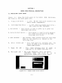
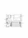
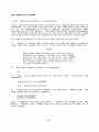
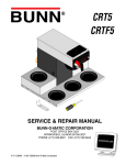
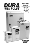
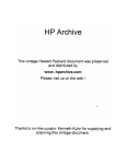
2.1 Maintrame Front Panel
ligure 2-1
show~ the tront panel ot the SUPEH
items on the tront panel are:
STAR
maintrame.
frile
1.
flo~py
Disk Drive
2.
Cartridge Disk Drive
3. H.un Switcb
5 1/4",
48 'l'Pl disk Or ive (Osborne arld
Xerox tormat compatable).
5 1 / 4 1\, 1 0 1Vi b wi r1C 11 est e r dis k d r i \t e 5Mb tixed and 5Mb removable.
Tbis switch is Lised to power ulJ or power the
cartridge disk drive.
4. Wrlte Protect Switch
5. Door Release
This switch is used to ~rite protect
the tixed disk protion ct the 10Mt
cartridge disk drive.
The release, when pressed opens tl1e cartridge
door tor the insertion Ot removal ot the
cartridge disk.
6.
Drive
Select LED
7.
Power
ON
8.
Run Light LED
LED
This 1iqhL wilen lit indicates WIlE=ll the
drive is ready to be accessed by tbe
SUPER STAR system.
This light indicates that AC power
supplied to tbe SUPER STAR when lit.
The light immeaiatly above the switch
indicates
when
the drivE: is
up
0pE.:rational speed (solid green light).
~li.'
"w ,",
~" :-;:$: ""
Figure 2-1. SUPER
S~AR
2-1
Front Panel
1S
to
I
Super
sta'..£J
2
7
8
3
SUPER STAR Physical Description
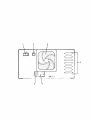
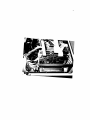
2.2
Maintrame Internal Parts
Figure 2-2 shows
system maintrame.
1.
2.
the major internal parts ot
the
SUPER
STAR
Internal Card Cage - The SUPER STAR system can support up to
six ditterent modules.
One SUPER QUAD
or SUPER SIX CPU module, one hard disk
controller, and up to tour SUPER SLAVE
modules tor mUlti-user applications.
Rear
Panel
Connector
- Ribbon cables which connect the
internal mOdules ot the SUPER STAR
system to the rear panel
and
external 1/0 devices. The maximum
number ot 1/0 connectors is seven.
NOTE
Care should be taken to assure the cable connector
is properly connected. The red edge ot the ribbon
cable always denotes Pin 1. You can assure proper
connection by making sure that the ribbon cable is
plugged into the connector with the pin 1 edge
aligned with the" n on the connector receptacle.
3.
Disk Drives - 5 1/4" and 10Mb disk drives.
4.
Cooling Fan
5•
Power
- The cooling tan circulates air to maintrame an
operating temperature which averages below 115
F inside the SUPER STAR system maintrame.
Supply
Figure 2-2.
- The power supply provides DC power to the
internal modules such as,
the CPU, disk
it
controller
and any Slave modules
present.
It also provides power to the
disk drives.
SUPER STAR system Internal Section.
2-2
3
SUPER STAR Pbysical Description
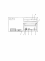
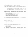
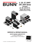
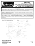
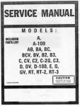
2.3
Maintrame Rear Panel
Figure
2-3 shows the rear panel ot the SUPER
The items on the rear panel are:
1.
Power On Switch
2.
Reset
Button
3.
Power
Cord
4•
Fuse -
5.
1/0
6.
Cooling Fan
STAR
maintrame.
Turns on the At power to the SUPER
system.
STAR
When this button is pressed,
the system is
reset
by
the
operating
system
and
the operating system sottware is reloaded
into system memory.
Plug
Supplies AC power connection tor
SUPER STAR.
the
The tuse provides line protection tor the SUPER STAR
system.
See Section 4 tor the proper type ot tuse
to use and how to replace or
change the power
requirement.
The tuse section contains a small
printed-circuit board to support both 110V and 220V
AC power.
These seven ports can support master
console, tour additional slave consoles,
a printerport and communications port.
Connectors
The cooling tan circulates air to maintain an
operating temperature which averages below
115 F inside the SUPER STAR system maintrame.
Figure 2-3.
SUPER STAR System Rear Panel.
2-3
2
6
o(
)0
o(
0\
)0
)0
o(
/0
0\
U~, ]:~
o
3
O(--~O
4
I
I
'i
Q)(:::::::~:':P II
tr"-- ------------------(Wi:>i.~J
;~ '"""..A.
-,0
5
Ii
----~
SECTION 3
INTERFACE CONECTORS
3.1
1ntertace Connectors Location
The SUPER STAR system has seven I/O intertace connectors located
on the rear panel as shown in Figure 2-3.
Five connectors are
25-pin type OB-25 connectors, which require a type DB-25 mating
connector tor intertace to serial peripheral devices. These tive
connectors are tor RS-232C compatible serial 1/0 intertace.
Two
connectors are parallel intertace ports (Centronics compatible)
and are 25-pin type DB-25 connectors that require type DB-25
mating connectors.
NOTE
Not allot these seven 1/0 intertace are necessarily
internally wirea to circuit boards in the SUPER STAR,
depending upon the contiguration you have ordered.
See
paragraph
3.4
entitled,
1/0
Connector
Contigurations.
3.2
Serial I/O Port Connectors
One ot the
tive serial 1/0 port connectors is intended tor
intertacing a monitor/keyboard/terminal console.
This connector
is intendea as Jl. The other tour serial 1/0 port connectots (J2
through J5) are intended tor intertacing a serial printer and/or
any other serial communications peripheral devices.
All
tive serial 1/0 port connectors have the
assignmentssince they are all RS-232C compatibe.
identities the pin assignments tor these connectors.
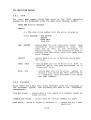
Table 3-1.
Serial 1/0 Port Pin
same
Table
pin
3-1
Assignm~nts
Signal Assignments
Pin No.
System Ground
TxD - Transmit Data
RxD Receive Data
Not Used
CTS Clear To Send
DSR Data Set Ready
Signal Ground
Not Used
Not Used
DTR Data Terminal Ready
Not Used
1
2
3
4
5
6
7
8
9-19
20
21-25
3-1
Interlace Connectors
3.2.1
Typical Three-Wire lntertace
The simplest 1/0 port intertace requires only three ot the serial
1/0 connector be wired. These three wires are: Pin 2-TxD, Pin 3RxD ana Pin 7-Signal Ground.
This three-wire contiguration will
satisty many serial devices and most terminals.
3.2.2
Four-Wire 1ntertace
Some serial devices require a "handshake" signal tor normal
protocol.
In
these
cases
the
tour-wire
intertace
contiguration will normally work. This contiguration is the safiLe
as the three-wire contiguration (pins 2,3 and 7 connected with the
additional tourth wire being pin 20 - DTR).
3.2.3
Serial Printer lntertace
Most serial printers require a "Busy" signal to maintain data
tlow.
With such printers,
the tour-wire contiguration will
normally work where pin 20 - DTR, is used as the "Busy" signal.
3.3
Parallel I/O Port Connectors
The two parallel I/O port connectors (J6 and J7) have the same
pin assignments and are Centronic printer compatible.
The pin
assignments tor these two connectors are shown in Table 3-2.
One ot the parallel I/O port 25-pin connectors is driven by the
SUPER QUAD PlO channel A,
the other is driven by the PlO channel
B.
Table 3-2 does not distinguish between A or B since both are
the same.
3-2
Interface Connectors
Table 3-2. Parallel 1/0 Port Pin Assignments
Pin Number
1
2
3
4
5
6-8
9
10
11
12
13
14
15
16
17
18
19
20
21
22-24
25
PIO Signal Name
Signal Function
ASTRB/BSTRB
PA2/PB2
PAO/PBO
Not Used
PAI/PBI
Not Used
PA3/PB3
Not Used
PA4/PB4
Not Used
PA5/PB5
Not Used
PA6/PS6
Not Used
PA7/PB7
Not Used
Strobe
Data Line 2
Data Line (3
Data Line 1
Data Line 3
Data Line 4
Data Line 5
Data Line 6
Data Line 7
ACKNLG
Not Used
BUSY
Not Used
Select
3-3
Intertace Connectors
3.4 1/0 Port Contigurations
The number ot the I/O port connectors that are actually connected
(through ribbon cables) to printed circuit boards inside the
SUPER QUAD is dependent upon the ~articular contiguration you
have selected tor your SUPER STAR system.
A CP/M-based single-user SUPER STAR system has tour ot the seven
1/0 port connectors available to the user (see options).
These
consist ot one parallel port connector and two serial ports
(Jl
and J2).
This contiguration will support a
terminal/keyboard
(one ot the serial ports),
one serial peripheral
(perhaps a
printer) and a parallel peripheral (printer, plotter,' etc.).
A TurboDOS-baseo multi-user SUPER STAR system can have trom tive
to the total seven 1/0 connectors available to the user depending
upon the number ot SUPER SLAVE modules installed in the SUPER
STAR. A tully contigured TurboDOS-based multi-user SUPER STAR can
support a master terminal/keyboard (one ot the tive serial 1/0
ports),
tour
remote user stations (the other serial 1/0 ports)
and two parallel 1/0 peripheral devices.
3.5 Internal Ribbon Cable Connectors
In case trouble is encountered with rear chassis 1/0 connectors
that
requires
an understanding ot the actual
pin-to-pin
allocations ot ribbon cables trom the SUPER QUAD or SUPER SLAVE
modules to the 1/0 connectors, reter to Appendix E. Under normal
use,
and during system contiguration this intormation is not
required and theretore is not presented in this section.
3-4
SECTION 4
SYSTEM SPECIFICATIONS
4.1 Introduction
This section presents speciticationjntormation on the overall
SUPER STAR system as well as individual subsystems (such as the
tloppy disk drive and the hard disk drive).
4.2
System Power Requirements
The SUPER STAR operates on 110 or 220 volts AC,
50-60 Hz power
and
is contigured at the tactory tor the power requirements ot
the country ot destination.
When contigured tor 110 VAC, the SUPER STAR is rated at 5 amperes
max.
(625 watts). When contigured tor 220 VAC, the SUPER STAR is
rated at 2.5 amperes max. (625 watts).
NOTE
It the SUPER STAR is not contigured tor the AC
power used at your tacility, reter to section
4.4, Changing AC Voltage, tor the proper procedure.
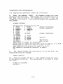
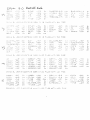
4.3 Specitication Tables
The tollowing tables present specitications
(and
operating
parameters) tor SUbsystems and circuit boards associated with the
SUPER STAR system. The subsystems covered by these tables are as
tollows:
Table 4-1
SUPER QUAD CPU Module
Table 4-2
SUPER SIX CPU Module (optional)
Table 4-3
Hard Disk Drive and Controller Subsystem
Table 4-4
Floppy Disk Drive
Table 4-5
SUPER SLAVE fvlodule
Table 4-6
SUPER STAR Overall Specitications
4-1
System Specitications
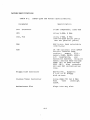
Table 4-1.
SUPER QUAD CPU Module Specitications.
Parameter
Bus
Specitication
Structure
5-100 Compatable, IEEE 696
CPU
zilog Z-80A, 4 MHz
SIO, PIO
zilog Z-80A, 4 MHz
(two Rs-232C serial ports
and two parallel ports)
RAt-1
64K bytes, bank selectable
(16K bytes)
ROM
2K (4K optional) 2716 EPROM
Monitor ~ontains BOOT
routine,
momory
FILL,
memory DUMP, PRINT, MOVE,
1/0
Read/Write,
and
Executive Address.
Occupies
memory address FOOO through
F800 (2K) or FOOO through
FFFF (4K).
Also contains
SID and FDC initialization
code.
Floppy Disk Controller
WD1793 FDC.
Supports
5 1/4" or 8" Floppy
disk drives.
Counter/Timer Controller
Zilog Z80A CTC tor 4 MHz
Real
Time
interrupt
clock.
Motherboard Slot
Plugs into any slot.
4-2
System Specitications
Table 4-2.
SUPER SIX CPU Module Specitications.
Parameter
Specitication
Bus Structure
5-100 Compatable, IEEE 696
CPU
Zilog Z-80B, 6 MHz
510, PIO
Zilog Z-80B, 6 MHz
(two Rs-232C serial ports
and two parallel ports)
RAM
64K or 128K bytes (optional),
bank selectable (16K bytes)
ROM .
2K (4K optional) 2716 EPROM
Monitor· contains
BOOT
routine, memory FILL,
memory DUMP, PRINT, MOVE,
1/0 Read/Write, and
Executive Address. Occupies
memory address FOOO through
FFFF (4K). Also contains 510
and FDC initialization code.
Floppy Disk Controller
WD2793 FDC. Supports
5 1/4" or 8" Floppy disk
drives simultaneously.
Counter/Timer Controller
Zilog Z80B CTC tor 6 MHz
Real
Time
interrupt
clock.
Motherboard Slot
Plugs into any slot.
4-3
System Specitications
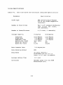
Table 4-3.
Hard Disk Drive and Controller Subsystem Specitications
Parameter
Specitication
Drive Type
DMA System's Micro-Magnum
5/5 or any ST506 compatible
intertace.
Number ot Disk Drives
Two 5 1/4" standard Winchester
type drives one tixed,
one removable.
Number ot Heads/Surtaces
4 (2 tixed, 2 removable)
Storage Capacity
Subsystem
Fixed Disk
Removable Disk
Sectors Per Track
Bytes Per Sector
Bytes Per Track
Data Transter Rate
Formatted
Untormatted
10.8 Mbytes
5.4 Mbytes
5.4 Mbytes
32+1 spare
256
8,192
12.8 Mbytes
5.4 Mbytes
5.4 Mbytes
33
304
10,032
5.0 Mbytes/sec
Data EnCOding Method
MFM
Step Rates
35 usecs (detault)
Selectable tor 0.5 to 7.5
usecs in 0.5 usec increments.
8.7 usec
Average Latency Time
Controller
HDC1001 plugs into any 5100
motherboard slot.
4-4
System Specitications
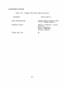
Table 4-4.
Floppy Disk Drive Specitications •
. Parameter
Specitication
Disk Contiguration
Double-density,double-sided
5 1/4" tloppy diskette.
Diskette Format
Osborne cornpatable (single
density)
Xerox cornpatable
KayPro compatable
(single density)
Tracks per Inch
48
4-5
System Specitlcations
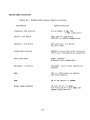
Table 45.
SUPER SLAVE Module Specitications.
Parameter
Specitications
Internal CPU Control
Zilog Z80A, 4 MHz CPU
6 MHz (optional)
Serial I/O Ports
Four Serial 1/0 ports
(RS232C or RS422 compatible)
Parallel I/O Ports
Two parallel 1/0 ports
25 pins each.
Interrupt Control
AMD9519 controller with vectorea
interrupt contiguration possible.
Bus Intertace
S100, IEEE696
Standard bus compatible.
Sottware
TurboDOS
system.
Controll
multi-user operating
RAM
64K or 128K bytes ot banked
switched memory.
ROM
2K or 4K bytes ot EPROM.
Power Requirements
+8 volt DC @ 1.5 Amps
+16 volts DC @ < 0.5 Amps per
SUPER SLAVE Module.
4-6
System Specltlcations
Table 4-6.
SUPER STAR Overall Specitications.
Parameter
Specitications
CPU Moaule
SUPER QUAD or optional
SUPER SIX module
Disk Controller
HDC10015 Hard Disk Drive
Controller module
1/0 Controller Modules
Up to tour SUPER SLAVE
modules
tor peripheral
controller.
Number ot Motherboard
Card Slots
6
Hard Disk Drive
DMA MicroMagnum 5/5
5 1/4" 10 Mbyte (5 Mbyte tixed,
5 Mbyte removable) Disk Drive.
Floppy Disk Drive
48 TPI Floppy Disk Drive
5 1/4", low protile, 308
bytes, double density,double
sided diskette.
Operating System
Single User
MultiUser
TurboDOS 1.30
CP/M 2.2
CP/M 3.0
TurboDOS 1.30
Power Requirements
110 VAC, 5 A, 625 watts
220 VAC, 2.5 A, 625 watts
Dimensions
Height 6.5 inches (16.51 cm)
Width 13.5 inches (34.29 cm)
Length 15 inches (38.10 cm)
4-7
System Specitications
4.4 Changing AC Input Voltage trom 110/220 to 220/110
!
1.
Remove the power cord trom the rear ot the system it it is
connected. Slide the plastic cover which is covering the tuse to
The plastic cover should now be covering the power
the lett.
plug.
2.
Gently pull on the black tab to remove the tuse.
The tab
releases the tuse trom its holder and will pivot tram the lett-hand
end ot the tuse.
3.
Remove the tuse and set it aside.
Using a pair ot small pliers, gently pull ~he small circuit
card straight out at the slot holding it. Be caretul not to bend
the board as this may cause the board to maltunction, causing
electrical damage to the SUPER STAR system.
4.
5.
Orient the board as shown below to set the proper AC power
specitication.
You will notice that the number which- is
rightside up, is the power speciticstion which the circuit board
will operate under.
220 Setting
110 Setting
CAUTION
Do not use the incorrect setting on the circuit
board as this may cause severe electrical damage
to your system.
6.
Gently reinsert the circuit board into the slot, again being
caretul not to bend the board.
7.
Press the tuse back in place.
PreSSing the tuse into place
causes the black tab to move back into its original position and
locks the tuse in place.
8. Slide the clear plastiC window back over the tuse and replace
the power cord in the socket to supply power to the system.
4-8
II
3":. n .:i •.
.:
;1;~)<3 H~~
l~
.
. ... .. ... .
..
I
.. .. '" ..
.. ..
"'11'
..
..
..
I
.
r '_J :. E.
.. .....................
................
""
..................
. . ..........
...... " " ..
....................
.. .. .. .. .. .. .. .. .. .. .. .. . . .. . .. .. .. .. .. ..
........................
H ['i!-l
.. .. . .. .. . .. .. .. .. .. .. .... .. ... .. ... . ... .. ... .. ... .. .... . .... .. .. ..
.. .... .. .... .. .... .. .... .. ... ,. .... ..................
.. .. ....
.. .... .. ..
. .. ..
.. .. .
..
..
. .. ....................
. .. .. .. . .. .. . .. .. .... . ..
. . ....................
.. .. .. . .. . . .. . .. .. ..
.....
.. .. .. .. .. .... .. .... . .... . .... .. .... .. ... .. .... .. .... .. .... .. .... .. .... . .... .. .
.. ............................
........................ . ..
. .... ............................
........................ .. .
SECTION 5
INSTALLATION AND INITIALIZATION
This section explains the procedures necessary to setup and
initialize the SUPER STAR system.
There are operating system
backup procedures given tor both CP/M and TurboDOS operating
systems.
5.1
Installation Procedure
1.
Betore removing the SUPER STAR maintrame trom its shipping
container,
inspect the outside ot the container.
It any damage
is tound,
notity the shipping company and Advanced Digital
immediately.
2.
Caretully remove the SUPER STAR trom the shipping container.
Inspect the exterior ot the maintrame tor any damage.
It any
damage is tound, notity the shipping company and Advanced Digital
immediately.
3.
place
the
SUPER STAR maintrame on a level counter or
desk
top.
4.
Open the SUPER STAR maintrame by removing the cover and check
the seating ot the boards and cable connections.
5.
Connect the master console to the proper
rear panel
connector marked "1" at the rear ot the SUPER STAR system.
1/0
CAUTION
Check the tuse package at the rear ot the SUPER STAR
system. You should be able to read the lettering on
the small circuit board which is inserted under the
tuse.
It the number which you can read rightside up
is not the proper voltage STOP STOP STOP!!!
Turn to
Section 4.4, Changing AC Voltage and tollowing the
procedure listed there.
5-1
Installation and Initialization
5.1
Installation Procedure (continued)
6.
Turn the power switch to the OFF position on the console and
SUPER STAR it it is not already in that position. Connect the AC
power cord to the rear ot the SUPER STAR system. Connect the AC
power cord to the rear ot the console and plug it into a power
source, but do not power up the system console.
NOTE
The power switch on the SUPER STAR system is in
the OFF position it the power switch light is not
lit and ON when the the light in the power switch
is lit.
7.
Press the power switch ot the SUPER STAR into - the ON
position.
The LED on the switch should light.
The LED on the
tloppy disk drive should also be lit.
This indicates that the
SUPER STAR is trying to access data trom the tloppy disk drive.
8.
Open the cartridge drive door by pressing the disk release
button
(see Figure 2-1) and gently lowering the cartridge drive
door.
9.
Insert a cartridge, either blank (it using CP/M) or an
operating system (it using TurboDOS or CP/M 3.0) into the drive.
Make sure that the red write protect tab is in the lower
right-hand corner tacing you. The bottom ot the cartridge is the
side which ahs the circular metal plate,
this side must be
tacing down when the cartridge is inserted into the drive.
See
Appendix A it you are not tamiliar with diskettes and cartridge
disks.
Gently slide the cartridge into the drive,
pressing on
the lett tront side ot the cartridge disk,
until it is properly
seated.
10:
Close the drive door.
The cartridge should
position as the drive door is closed.
drop
into
11. Set the Write Protect Switch to the ON position. The switch
is in the "ON" position when the right-hand side ot the switch is
t1ush with the tront ot the disk drive.
This protects the data
on the cartridge trom being damaged or being written on.
12.
Press the RUN button to the ON position.
The switch is in
the "ON" position when the right-hand side ot the switch is tlush
with the tront ot the drive. The green run light should begin to
blink as the drive comes up to operating speed.
When the drive
is up to operating speed, the green light stops blinking and
remains lit and the red light or "ready"
light comes on to
indicate that the drive is ready.
5-2
Installation and Initialization
5.1 Installation Procedure (continued)
13.
It you are using thr CP/M 2.2 operating system with the
SUPER STAR, you could at this time insert a system diskette into
the t10ppy disk drive and load the system sottware into memory.
However,
it you do not tollow the rest ot the procedure listed
here you will not know it the hard disk drive is operational.
14.
Turn on the power to the system console it you
already done so.
have
not
15.
Press the reset button on the back ot the SUPER STAR system
(see Figure 2-3).
The system then access the disk system in the
tollowing manner:
1.
Checks the tloppy drive tor a disk containing a system
boot. This would be the drive which would have the CP/M
operating system it you are using that operating system.
2.
Checks the tixed hard disk tor a system boot. This may
be where you would normally like to store your operating
system whether it be CP/M 2.2, CP/M 3.0 or TurboDOS.
3.
The system then retires in the sequence lidted
tloppy, tixed disk, and back to the tloppy.
above,
It you wish to boot trom the cartridge you must use the tollowing
procedure:
IMPORTANT - This procedured must be tollowed when booting the
TurboDOS or CP/M 3.0 system contained on a cartridge tor the
tirst time, it is suggested that you copy the operating system to
the tixed disk to save time under normal operation.
1.
Hold the SPACE bar down and press the RESET button.
2.
The system boots and calls a system monitor routine
tollowed with a prompt >.
3.
Type H.
When the menu is displayed,
cartridge boot tollowed by a RETURN.
press
C
tor
4. The system reads the cartridge and loads the operating
system trom the cartridge disk.
5-3
Installation and Initialization
5.1
Installation Procedure (continued)
CP/M 2.2 Signon
Message:
CP/M 3.0 Signon
>ADVANCED DIGITAL CORPORATION
Monitor Version n.n
April - 1983
Press "8" tor help
Attempting to boot •••••
Press any key to abnort boot
/
>ADVANCED DIGITAL CORPORATION
f't10nitor Version n.n
April - 1983
Press "H" tor help
Attempting to boot •••••
Press any key to abort boot
Super BIOS vn.nn
Typeahead installed
C P / tv! V 3 ." Lo ad e r
60K CP/M 2.2 Installed
BIOS3
BIOS3
Copyr ight (C)
Detault console is serial port 1
Detault printer is parallel driver
A>
M~ssage:
SRP
SPR
1982, Dic Res
E500 1100
C600 IF00
49K TPA
Super BIOS v.3.0
CP/M 3.0 Installed
Detault console is serial device 0
Detault printer is palallel device
A>
TurboDOS Single-User Terminal Signon Message:
>ADVANCED DIGITAL CORPORATION
Monitoer Version 3.6
April - 1983
Press "8" tor help
Attempting to boot •••••
Press any key to abort boot
Copyright 1983, Sottware 2000, Inc. -(21/serial no.)
A:OSMASTER,SYS loading trom EFF4 to FFFF, size 400C
TurboDOS 1.30, Copyright 1983, Sottware 2000, Inc. (serial no.)
Super Six [or Quad] up.
OA}
NOTE
It the system is being booted trom the cartridge the
prompt is OB}.
The message "Super Six up" or
"Super
Quad up"
indicates
the type at CPU module you are
using.
5-4
Installation and Initialization
5.1
Installation Procedures (continued)
TurboDOS Multi-User Master Terminal Message:
>ADVANCED DIGITAL CORPORATION
Monitor Version 3.6
April - 1983
Press "8" tor help
Attempting to boot •••••
Press any key to abort boot
Copyright 1983, Sottware 2000, Inc. (2l/serial no.)
A:OSMASTER.SYS loading trom BFF4 to FFFF, size 400C
TurboDOS 1.30, Copyright 1983, Sottware 2000, Inc. (21/serial no.)
Super Six [ or Quad] up.
OAl
TurboDOS Multi-User Slave Terminal Signon Message:
>ADVANCED DIGITAL CORPORATION
Monitor Version n.n
April - 1983
Press "B" tor help
~ttempting to boot •••••
Press any key to abort boot
Copyright 1983, Sottware 2000, Inc. (21/serial no.)
Advanced Digital Copr. Super Slave Bank up.
OAl
NOTE
The message "Super Slave Bank up" or "Super Slave
Non-bank up" is displayed depending on whether you
are running a banked system or not.
It the system
does not display the signon message within 10 secondS,
press the reset button again. It this does not correct
the problem, check allot steps listed above and try
again. It this routine still tails reter to Section 8.
5-5
Installation and Initialization
5.2 Initial System Power-Up
When you tirst receive the Super Star system,
a
copy ot
the
system sottwareshould be made by placing a blank cartridge
into
the 10 MMb drive (hard disk) or a blank diskette into the tloppy
disk drive.
The actual backup procedure tor both the TurboDOS
and CP/M operating systems are discussed in Sections 5.3 and 5.4,
respectively.
The Super Star system is designed to tirst, access the tloppy disk
drive to
locate an operating system to be loaded
into system
memory.
It a disk or operating system is not tound in the tloppy
drive,
the system then accesses the tixed portion ot the 10 Mb
hard disk drive.
When the Super Star is shipped to you,
a copy ot the operating
system is provided on the cartridge disk
tor TurboDOS or
cartridge tor CP/M 3.0 users,
or tloppy disk tor CP/M 2.2 users.
The startup procedure discussed in Section 5.1 is the general
startup procedure
tor
either operating system
(TurboDOS or
CP/M).
It
is suggested by Avanced Digital that you use
the
tixed
portion ot the hard disk as your normal operating system disk.
The cartridge disk and tloppy diskettes can be used tor
storage
ot development sottware, applications and operating system backup
sottware.
The cartridge disk is always used in the upper halt ot the hard
disk drive and must be inserted with the red write protect tab
in the lower right-hand corner.
The side ot the cartridge with
the metal disc
is termed the bottom side ot
the cartridge.
Appendix A provides turther intormation on the proper
use and
care ot cartridge disks.
NOTE
The tollowing paragraph applies to SUPER STAR systems
which are developed with CP/M 2.2 operating system or
it you intend to use tloppy distettes with your system.
The
tloppy diskettes are always used in the upper drive ot
the
SUPER STAR and must be inserted with the level up.
The lable
side ot
the diskette is termed,
the top side ot the diskette.
'Read Appendix A tor the prope~ care and handling ot
tloppy
diskettes.
All diskettes used in the SUPER STAR system must be
certitied
tor
use with double density,
double-sided 48 TPI,
5 1/4" drives.
5-6
Installation and Initialization
5.3
Copying The System Disk (TurboDOS)
This section describes the protcedure tor copying the operating
system trom the cartridge disk to the tixed portion ot the hard
drive using the TurboDOS system.
This procedure can also be
tollowed
it the operating system on your tixed disk
is damaged
and must be reloaded trom a backup cartridge or tloppy.
It you
have a "SUPER STAR" system with the CP/M operating system,
skip
to Section 5.4 tor the proper copy procedure.
To copy the system disk, proceed as tollows:
1.
Power the system.
2.
Power up the hard drive by pressing the run button on the
hard drive.
When the drive is up to operating speed, reboot the
system by pressing the reset button on the back panel ot the
SUPER STAR system.
Press the Run button and the R/W button on
the hard disk drive.
3.
Insert a cartridge disk containing the operating system into
the 10 Mb drive it you have not already done so.
This must be
done in order tor the system to boot.
4.
Hold the
5.
The
prompt -
SPACE bar down and press the RESET button.
system
>.
boots and calls a system routine tollow with
6.
Typy H.
When the menu is displayed,
boot tollowed by a RETURN.
a
press C tor cartridge
7. The system reads the cartridge and loads the operating system
trom the ca~tridge disk.
8.
The logon message is displayed and
prompt is displayed:
OBI
the
TurboDOS
command
9.
Type, BUFFERS N2. This command initializes your terminal as
the master terminal or console.
OBI BUFFER2 N2[RETURN]
(only it you are running with a SUPER
OBI BANK O[RETURN]
SIX in banked mode in either a multiuser or single-user sysetem.)
5-7
31
Installation and Initialization
5.3
Copying The System Disk (TurboDOS)
(continued)
10.
Enter the command, FORHDC A. This command displays a menu
ot ditterent types ot drives to tormat. This command tormats the
tixed portion ot the hard disk.
TurboDOS assigns the csrtridge
portion ot the hard disk as drive B,
the tixed portion drive A
and the tloppy drive as drive C.
NOTE:
When running TurboDOS
with slaves this operation must be done trom the master terminal.
The tollowing set ot prompts shows the system displays:
OB}FORHDC A: [RETURN)
Hard Disk selection choices ***
1 =ST506
;Seagate Technology
=ST503
3 =TM602S
;Tandon Magnetics
2 =TM6015
4 =TM603S
5 =TM603SE
6 =TM501
7 =TM502
8 =TM503
;Shugart Associates
10 =SA604
9 =SA602
11 =SA606
12 =SA1002
13 =SA1004
14 =Q2010
15 =Q2020
iQuatum
16 =Q2030
17 =Q2040
18 =M4010
19 =M4020
;MiniScribe
20 =DMA5/5
;DMA System
?(tor DMA drive, you would enter 20 here)
INSERT DISK TO BE FORMATTED IN DRIVE A
ENTER <CR) TO BEGIN FORMATTING
***
o
·..... ... .... .. . ... .. . .
·........ ....... . ......
· .. .. . . . . .. .. . . . . . . . . . .
Start verity
·. . . . . . . . . . . . . . . . . . . . . .
· .. ...... . .. ... ... . ... .
OB}
11.
Enter the command, ERASEDIR A:.
This command clears
initializes a directory that may have been previously written
the disk. Press RETURN:
or
on
OB}ERASEDIR A: (RETURN)
12.
The system displays a series ot questions,
tollowing manner:
Hashea directory desired (YIN)? Y
OK to erase directory on drive A? Y
Erasing directory
5-8
answers in the
Installation and Initialization
r
5.3
Copying The System Disk (TurboDOS)
(continued)
13.
The system then erases the directory and then displays:
Directory erased, hashed
OB}
14.
Enter the command, BACKUP B: A:. This command copies allot
the data currently stored on the cartridge disk (B) to the tixed
disk (A):
OB}COPY B: A:
15.
The system
to press RETURN:
[RETURN]
then displays the tollowing and waits tor
you
Insert source d~sk io dr~ve A.
Insert dest1nat1on d1Sk 1n dr1ve B
Enter (cr> to begin copying:
16.
Enter TKOBOOT TRKOMA.LDR A:
onto the tixed disk.
OB}TKOBOOT TRKODMA.LDR A:
to copy the track zero
loader
[RETURN]
This completes the copy procedure.
Power down the drive and
remove your cartridge with the operating system trom the drive.
Store this cartridge away in a sate location in case it is ever
needed.
5-9
Installation and Initialization
5.4
Copying The System Disk (CP/M 3.0)
This section describes the procedure tor copying the operating
system trom the cartridge disk to the tixed portion ot the hard
drive using the CP/M 3.0 systems.
This procedure can also be
tollowed
it the operating system on your tixed disk is damaged
and must be relocated tram a backup cartridge or tloppy.
It you
have a SUPER STAR system with the CP/M 2.2 operating system, skip
to Section 5.5 tor additional intormation.
To copy the system disk, proceed as tallows:
1.
Insert a cartridge disk containing the operating system into
the 10 Mb drive it you have rot already done so.
2.
Power up the hard drive by pressing the run button on the
When the drive is up to operating speed, reboot the
hard drive.
system.
3.
Hold the SPACE bar down and press the RESET button.
4.
The system boots and calls a system monitor routine
with a prompt - >.
tollow
5.
Type HELP. when the menu is displayed, press C tor cartridge
boot tollowed by a RETURN.
6.
The system reads the cartridge and loads the operating system
trom the cartridge disk.
7. The logon message is displayed and the CP/M command prompt is
displayed:
A>
5-10
Installation and Initialization
- 5.4
Copying The System Disk (CP/M 3.0)
(continued)
8.
Enter the command, FMTHD.
This command tormats the tixed
portion ot the hard disk.
CP/M assigns the cartridge portion ot
the hard disk as drive A,
the tixed portion drive B and the
t10ppy drive as drive C.
The tollowing prompts are displayed by
the system:
A)FMTHD [RETURN]
***
Hard Disk selection choices ***
iSeagate Technology
1 =ST506
iTanaon Magnetics
3 =TM602S
2 =TM6015
4 =TM603S
5 =TM603SE
7 =TM502
6 =TM501
8 =TM503
iShugart Associates
10 S1\604
9 =SA602
11 =SA606
12 =SA1002
13 =SA104
iQuantum
14 =Q2010
15 =Q2020
16 =Q2030
17 =Q2040
18 =M4010
19 =M4020
iMiniScribe
20 =DMA5/5
;DMA Systems
Enter Drive to Format: 20 (selection)
Do you want to tromat the Cartridge, Fixed or Both [C, F or B]? F
Which physical disk do you want to tormat (0-3)?0
This operation will destroy all data on drive 0.
Hit return to continue or Control-C to abort.
o =ST503
OA)
9.
The system tormats the tixed portion ot the hard disk
disp1ys the to11owint message:
and
Format complete
10.
Enter the comand, ERA B:*.*. This command erases any entry
in the current directory.
This system asks it you want to erase
all tiles:
~)ERA
B:*.*[RETURN]
ALL(Y,N) Y
5-11
Installation and Intialization
5.4 Copying The System Disk (CP/M 3.0)
(continued)
11.
When the system has completed the tormatting ot the disk,
enter the LDRGEN cgmmand.
This command should only be used it
you intend to boot trom the tixed drive when powering up the
system.
It you do not want the system to boot trom the tixed
disk then skip to Step 13.
The LDRGEN command puts a track zero
loader onto the hard disk you are creating:
A)LDRGEN T30DMA55.LDR[RETURNl
Physical drive no. ot loader destination (0-3):0
Write loader to cartridge or tixed [C or Fl:F
12.
Press RETURN.
The system copies the
cartridge drive to the tixed hard disk.
loader
trom
the
13.
Copy the tile CPM.SYS trom the cartridge to the tixed disk
as to1lows:
A)PIP B:CPM.SYS=:CPMH.SYS[RETURNl
14.
The tile CPM.SYS is copied to the tixed hard disk.
15.
Next, set the tile CPM.SYS to read-only status:
A)STAT B:CPM.SYS $R/O[RETURN]
16.
Once the CPM.SYS tile is set to read-only, copy the rest ot
the system disk to the tixed disk.
A)PIP B:A:*.*[v] [RETURN]
[v] - alows veritication
17.
When this is complete compare the two disks, master and new
copy using the directory command:
A)DIR A: [RETURN]
Directory A is displayed by the system
A)DIR B:[RETURN]
Directory B is displayed by the system
This completes the copy procedure.
Power down the drive and
remove your cartridge with the operating system trom the drive.
Store this in a sate location.
5-12
Installation and Initialization
5.5
Copying The System Disk
(CP/M 2.2)
This section describes the procedure tor
copying the operating
system trom the tloppy disk to the tixed portion ot the hard
drive using the CP/M system.
This procedure can also be tollowed
it the operating system on your tixed disk is damaged and must be
reloaded trom a backup tloppy.
To copy the system disk, proceed as tollows:
1. Insert a tloppy disk containing the operating system into the
tloppy disk drive it you have not already done so.
2.
Power up the hard drive by pressing the run button on
the
hard drive.
Remember
that you must have a cartridge disk
inserted betore the hard drive will operate.
When the drive is
upto operating speed,
reboot the system by preSSing
the reset
button on the back panel ot the SUPER STAR system.
3.
The
logon
displayed:
message
is displayed and the
CP/M
command
is
A)
4.
Enter
the
portion ot the
the hard disk
tloppy drive as
command, FMTHD.
This command tormats the
tixed
hard disk.
CP/M assigns the c~rtrige portion ot
as drive C,
the tixed portion drive B and
the
drive A)
A)FMTHD (RETURN]
Do you want to tormat Cartridge, Fixed or Bottl[C, F or B]?F
Which physical disk do you want to tormay (0-3)?0
This operation will destroy all data on arive 0.
Hit return to continue or Control-C to abort.
OA)
5.
The system tormats the
tixed portion ot
and displays the tollowing message:
the
hard
disk
Format complete
6.
Enter the command, ERA B:*.*.
This command erases any entry
in thr current directory.
This system asks it you want to erase
all tiles:
A)ERA B:*.*[RETURN]
ALL(Y,N)Y
5-13
Installation and Initialization
5.5
Copying The System Disk (CP/M 2.2)
(continued)
7.
When the system has completed the tormatting ot the disk,
enter
the LDRGEN command.
This command should only be used
it
you
intend to boot trom the tixed drive when powering up the
system.
It you do not want the system to boot trom the tixed
disk then skip to Step 10.
The LDRGEN command puts a tract zero
loader ono the hard disk you are creating:
A)LDRGEN TRKODMA55.LDR[RETURN1
8.
The system displays
answered as tallows:
a series ot questions which
must
be
Physical drive no. ot loader destination (0-3):0
Write loader to cartridge or tixed [C or F1:F
9.
Press RETURN.
The system copies the loader trom the
drive to the tixed disk.
10.
Copy
tollows:
tloppy
the tile CPM.SYS trom the tloppy to the tixed disk as
A)PIP B:CPM.SYS=A:CPMH.SYS[RETURN1
11.
The tile CPM.SYS is copied to the tixed hard disk.
12.
Next, set the tile CPM.SYS to read-only status.
A)STAT B:CPM.SYS $R/O[RETURN1
13.
Once the CPM.SYS tile is set to read-only, copy the rest ot
the system disk to the tixed disk:
A)PIP B:A:*.*[v1 [RETURN1
[v1 - allows veriticatian
5-14
Installation and Initialization
5.5 Copying The System Disk (CP/M 2.2)
(continued)
14.
When this is complete compare the two disks, master and new
copy using the directory command:
A)DIR A: [RETURN]
Directory A is displayed by the system
A)DIR B:[RETURN]
Directory B is displayed by the system
This completes the copy procedure.
Power down the drive and
remove your
tloppy with the operating system trom the drive.
Store this tloppy away in a sate location.
5-15
SECTION 6
THE OPERATING SYSTEM
6.1
Introduction
This section describes the operating system sottware packages
under which the SUPER STAR system pertorms both
inteInal and
external tunctions or operations.
When contigured as a singleuser system, SUPER STAR operates under the control ot CP/M,
a
Digital Research-developed sottware system. When contigured as a
multi-user system,
the SUPER STAR operates using TurboDOS,
a
CP/M-like operating system which supports multi-user operations.
These two operating system packages are brietly described in this
section.
Each SUPER STAR system is delivered with a separate
user's document tor the system you have selected.
In addition,
this
section
covers
contiguration
considerations
and
initialization procedures,
such as,
copying ot diskettes and
transtering data trom one drive media to another.
6.2
Contiguring the SUPER STAR System
This section describes the standard contiguration ot the SUPER
This section also provides
STAR system under CP/M and TurboDOS.
you with some helptul setup procedures you may want to use when
running TurboDOS.
It you are presently running the CP/M
operating system on your SUPER STAR system, these setup ideas are
not
needed.
This section also provides
some
necessary
intormation about contiguring the SUPER SLAVE modules tor use in
the multi-user system.
6.2.1
SUPER STAR CP/M Hardware Contiguration
One SUPER QUAD CPU Module (CP/M 2.2 Operating System)
One Hard Disk Controller Module
One Floppy Disk Drive, 5 1/4", 48TPI
One 10Mb Hard Disk Drive, 5Mb removable, 5Mb tixed
Optional ~ SUPER SIX CPU MOdule (CP/M 3.0 OPerating System)
The placement ot the modules within the SUPER STAR card cage
is
not bus dependent and theretore,
can be places in any slot you
wish.
6-1
The Operating System
6.2.2 SUPER STAR TurboDOS Hardware Contiguration
Standard:
One
One
One
One
SUPER QUAD CPU MOdule
Hard Disk Controller MOdule
Floppy Disk Drive, 5 1/4", 48TPI
10Mb Hard Disk Drive, 5Mb removable, 5Mb tixed
Optional:
SUPER SIX CPU MOdule
Up to tour additional SUPER SLAVE Modules
As
in the case ot the CP/M system,
the placement ot the modules
within the SUPER STAR
card cage is not bus dependent and
theretore, can be placed in any slot you wish.
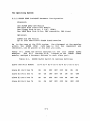
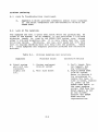
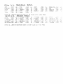
Table 6-1 shows the switch settings tor the
tour SUPER
modules.
The Sl-1 through Sl-8,
located on the SUPER
module, assigns a hardware address to each slave port.
Table 6-1.
SLAVE
SLAVE
SUPER SLAVE Switch Sl Address Settings
Slave and Port Number
S1-8 S1-7 S1-6 S1-5 Sl-4 Sl-3 S1-2 Sl-1
Slave 11 Port hex 70
ON
ON
OFF
OFF
OFF
ON
ON
ON
Slave 12 Port hex 72
ON
ON
OFF
OFF
ON
ON
ON
OFF
Slave 13 Port hex 74
ON
ON
OFF
OFF
OFF
ON
OFF
ON
Slave 14 Port hex 76
ON
ON
OFF
OFF
OFF
ON
OFF
OFF
6-2
The Operating System
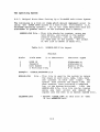
6.2.3
Helptul Hints When Setting Up a TurboDOS Multi-User System
The tollowing is a list ot items which should implement prior to
using the SUPER STAR system in a multi-user environment
(i.e,
TurboDOS operating system).
Allot the items mentioned here are
discussed in greater detail in the TurboDOS User's Manual.
USERID.SYS File - This tile should be created, using any
text editor, and placed in the master
console directory, user id, password,
tor each user on the system. The tormat
ot the tile is shown in Table 6-2.
Table 6-2.
USERID.SYS File Layout
Maximum
Field
1
2
3
Field Name
•
ot Characters
USER ID
8
Password
8
User Number
2
& Privilage Flag
Example:
Character Types
Alphanumeric
Alphanumeric
Numer ,ic 0- 30 ,
P or blank
USERID,PASSWORD,O,P
SYSLOG .SYS
COLDSTRT.AUT
File - This tile is used by the system to record
the logon ot each user, name, time, date
and process ot each user logon.
The
system also records the logott time tor
each session, thus providing a complete
log ot the system activites.
Like the
USERID.SYS tile, this tile can be created
using any text editor and should be
copied into the User 31 or master system tile.
- Rename "LOGON.COM" to this tile in
31 tor WARMSTRT.AUT.
6-3
User
The Operating System
6.2.3
Helptul Hints When setting Up a TurboDOS Multi-User System (cont.)
WARMSTRT.AUT
File
- This tile is simply a
tile with the
LOGON command copied into it. When this tile
is present in the master system tile
(User 31),
the system automatically
executes the LOGON command at system start-up
and at the end ot each LOGOFF command
sequence.
Simply copy the LOGOFF
command into this tile and store it in
the USER 31 system tile.
A sample dialog tor setting up your system with a user id tile:
1.
Using a text editor create a tile called: USERID.SYS
2.
Insert records tor each user, Examples:
JIM,SAMPLE,O,P
SUSAN,MYFILE,IO,P
3.
Copy the USERID,SYS tile
WARMSTRT.AUT in User 31.
to User
31
and
LOGON.COM
to
COpy USERID.SYS,D31
COpy LOGON.COM,WARMSTRT.AUT:D31
4.
Edit the tile called SSLAVENBNK.PAR.
and change as shown:
AUTOUSER
5.
=
8~
------) AUTOUSER
Find the lable AUTOUSER
=
OFF
Close this tile and enter the command:
GEN SSLAVEBNK OSSLAVE.SYS
6.3
Basic Operating System Structure
This section provides a briet description ot the two operating
systems which are available to the user ot the SUPER STAR
computer system.
6-4
· .... 1
The Operating System
6.3.1
CP/M
CP/M, Cont~ol Program tor Microprocessors,
is the operating
system which you will be using it you have a single-user SUPER
This operating system has been commersially
STAR system.
available since 1975 and become a standard in the microcomputer
industry. It has been a wide variety ot disk management commands
and usetul 1/0 commands tor the user. Because CP/M has become so
popular there is an extencive library ot sottware, both business
and scientitic available to you,
the user.
CP/M 2.2
is the
standard operating system available with the SUPER STAR system,
CP/M 3.0 are available as an option tor the SUPER STAR system.
6.3.2
TurboDOS
TurboDOS, like CP/M, is a computer operating system. TurboDOS is
the system you will be using it you are going to operate the
SUPER STAR system in a mUlti-user environment.
This operating
system is totally CP/M-compatable,
thereby allowing you to load
and
execute any CP/M programs which you have
developed.
TurboDOS also provides increased disk storage capacity ot 25% to
35% over that ot the single user CP/M SUPER STAR system.
6.4
Single User System (CP/M 2.2)
The
tollowing sections describe tunctions and the commandS that
execute those tunctions using the CP/M 2.2 operating system.
It you are currently using the CP/M 3.0 operating system skip to
Section 6.7 tor the TurboDOS operating system.
6.4.1
Copying Hard Disk to Diskettes
This section d~scribes the procedure tor copying data trom
hard disk to ~-~loppy disk.
the
To COE~rthe hard disk to a diskette, proceed as tallows:
/
~~/
Power up the system it it is not already running.
The
/operating system is assumed to be currently loaded on the tixed
// portion ot the hard diS'k drive.
2.
Insert a tloppy disk you want to copy data into the
disk drive it you have not already done so.
6-5
tloppy
The Operating System
6.4.1
Copying Hard Disk to Diskette (continued)
3. The logon message is displayed and the CP/M command prompt is
displayed:
A) - Where A is the tixed disk. The system assigns A to the
tixed disk when the system is booted trom the tixed disk.
The system assigns the tloppy disk as drive C and
cartridge disk as B.
4.
Enter the command, FMT548. This command tormats the diskette
currently installed in the tloppy disk drive.
CP/M assigns the
tloppy disk drive C.
A)FMT548 [RETURN]
Enter Disk Drive to be cormatted {0-3):0
Format Single or Double Sided (5,0):0
Format System Tracts only {Y:N):N
Surpress Format Veritication (YiN):N
Insert Diskette Into Drive 0 and Press The Return Key
5.
The system tormats the diskette installed in the tloppy disk
drive and displayes the tollowing message:
Format complete
6. Use the PIP command to copy allot the tiles trom your source
diskette to the new one:
A)PIP C:=A:*.*[v] [RETURN]
[v] - allows veritication
7.
In order to assure that the copy was successtul,
directories using the DIR command and compare them:
check both
A)DIR A: [RETURN]
A)DIR C:[RETURN]
This completes the copy procedure.
Remove the copy and
this tloppy away in a sate location until it is needed.
6-6
store
The Operating System
6.4.2
Copying Hard Disk to Cartridge (continued)
6. In order to assure that the copy was successtul,
directories using the DIR command and compare them:
check
both
A)DIR B:[RETURN]
A)DIR A: [RETURN]
7.
It you want to make the cartridge bootable use
write the track 0 loader:
LDRGEN
to
A)LDRGEN TODMA5.LDR[RETURN]
Physical drive no. ot loader destination (0-3):0
Write loader to cartridge or tixed (C or F):C
This completes the copy procedure.
Remove the copy and
this cartridge away in a sate location until it is needed.
6.4.3
store
Copying Cartridge to Diskette
This section describes the procedure tor copying data
cartridge to the diskette drive.
trom
the
To copy the cartridge disk, proceed as tollows:
1. Insert the cartridge to be copied into the hard disk drive it
you have not already done so.
2.
Power up the hard drive by pressing the run button on the
hard drive. Wait tor the run drive to come up to operating speed.
3.
The logon
displayed:'
message
is displayed and the
CP/M
command
is
A) - Where A is the tixed disk. The system assigns A to the
tixed disk when ·the system is booted trom the tixed
disk.
The systems assigns the tloppy disk as drive C
and cartridge disk as B.
6-8
The Operating System
6.4.2
Copying Hard Disk to Cartridge
This section describes the procedure tor copying data trom
hard disk to a cartridge disk.
the
To·copy the hard disk to a cartridge, proceed as tollows:
1.
Power up the system it it is not already running.
The
operating system is assumed to be currently loaded on the tixed
portion ot the hard disk drive.
2.
The logon
displayed:
message
is displayed and the
CP/M
command
is
A) - Where A is the tixed disk. The system assigns A to the
tixed disk when the system is booted trom the tixed
disk.
The system assigns the tloppy disk as drive C
and cartridge disk as B.
3.
Enter the command, FMTHD. This command tormats the cartridge
currently installed in the hard disk drive.
CP/M assigns the
cartridge disk drive B.
A)FMTHD [RETURN]
[MENU DISPLAYED]
Enter drive to tormat: 20 (selection)
Do you want to tormat the Cartridge, Fixed or Both [C,F orB):C
Which physical disk do you want to tormat (0-3)? 0
This operation will destroy all data on drive 0.
Hit return to continue or Control-C to abort.
4.
The system tormats the cartridge installed in the tixed disk
drive and ~isplays the tollowing message;
Format complete
5.
Erase any entries in the directory and use the PIP command to
copy allot the tiles trom your tixed disk to the cartridge:
A)ERA B:{+[RETURN)
ALL(Y,N) Y[RETURN]
A)PIP B:=A:*.*[v) [RETURN)
[v) - allows veritication
6-8
The Operating System
6.4.3 Copying Cartridge to Diskette (continued)
4. Enter the command, FMT548. This command tormats the diskette
currently installed in the tloppy disk drive.
CP/M assigns the
tloppy disk drive C.
A)FMT548 [RETURN]
Enter Disk Drive to be tormatted (0-3}:0
Format Single or Double Sided (S,D):D
Format SYstem Tracts only (Y,N}:N
Suppress Format Veritication (Y,N):N
Insert Diskette Into Drive 0 and Press The Return Key
5.
The system tormats the diskette installed in the tloppy disk
drive and displays the tollowing message:
Format complete
6.
Copy
command:
the
cartridge data to the tloppy disk using
the
PIP
A)PIP C:=B:*.*[v] [RETURN]
[v] - allows veritication
7.
When this is complete compare the two disk, master and new
copy using the directory command, allot the tiles trom the
cartridge disk should now also be listed in the tloppy disk
directory:
A)OIR B:[RETURN]
A)DIR C:[RETURN]
This
completes the copy procedure.
6.4.4 Copying Cartridge to Fixed Disk
This section describes the procedure tor copying data trom
cartridge to tixed portion ot the hard disk drive.
the
To copy the cartridge disk, proceed as tollows:
1. Insert the cartridge to be copied into the hard disk drive it
you have not already done so.,
6-9
The Operating System
6.4.4 Copying Cartridge to Fixed Disk (continued)
2.
Power up the hard drive by pressing the run button on the
hard drive. Wait tor the drive to corne up to operating speed.
3. Enter the command, FMTHD. This command tormats the hard disk
drive.
CP/M assigns the cartridge disk drive B.
A)FMTHD (RETURN]
[MENU DISPLAYED]
Enter drive to tormat: 20 (selection)
Do you want to tormat the Cartridge, Fixed or Both (C,F orB]7F
Which physical disk do you want to tormat (0-3)70
This operation will destroy all data on drive 0.
Hit return to continue or Control-C to abort.
4.
The system tormats the tixed disk and displays the tollowing
message:
Format complete
5.
Enter the command, ERA A:*.*.
This command erases any entry
in the current directory.
This system asks it you want to erase
all tiles:
A)ERA A:*.*[RETURN]
ALL (Y , N) Y
6.
Copy
command:
the
cartridge
data to the tixed disk using
the
PIP
A)PIP A:=B:*.* [v) [RETURN]
[v] - allows veritication
7.
When this is complete compare the two disk,
master and new
copy using the directory command,
allot the data tiles trom the
cartridge disk should now also be listed in the
tixed disk
directory:
A)OIR A: [RETURN]
A)OIR B: [RETURN]
This completes the copy procedure.
6-10
The Operating System
6.4.5
Copying Diskettes to Fixed Disk
This section describes the procedure tor copying data stored ~n
diskette
to the tixed disk portion ot the 10Mb hard disk drive.
It
it
is necessary to create a
backup system diskette
read
Section 5.4 ot this manual.
The CP/M operating system designates
the cartridge disk as drive B and the tixed portion ot the tixed
drive as drive A when the system is booted trom the tixed disk.
To copy a diskette to the tixed disk, proceed as tollows:
1.
Insert a tloppy disk containing the data you want to save or
copy into the tloppy disk drive it you ahve not already done so.
NOTE
The system must already be running prior to
loading the source diskette into the tloppy
disk drive.
It this is not done, the system
attempts to read the operating system tram
the tloppy disk which will cause error it it
is not a system disk.
2.
The CP/M command prompt is displayed:
A)
3.
Copy
'command:
the tloppy disk data to the hard disk,
using the
PIP
master and
new
A) PIP A: = C : * • * [ v] [R E TU RN 1
[v] - allows veritication
4.
copy
When this is complete compare the two disk,
us~ng the directory command:
A) 01 R A: [RETURN]
A)OIR C: [RETURN]
This completes the copy procedure.
Remove the tloppy trom the
drive.
Store this tloppy away. in a sate location in case it is
ever needed.
6-11
The Operating System
6.4.6 Copying Diskettes to Cartridge
This section describes the procedure tor copying data stored on
diskette to
the cartridge portion ot the 10Mb hard disk drive.
It
it is necessary to create a
backup system diskette read
Section 5.4 ot this manual. The CP/M operating system designates
the cartridge disk as drive B and the tixed portion ot the tixed
drive as drive A when the system is booted trom the tixed disk.
To copy a diskette to the cartridge disk, proceed as tollows:
1.
Insert a tloppy disk containing the data you want to save or
copy into the tloppy disk drive it you have not already done so.
NOTE
The system must already be rumming prior to
loading the source diskette into the tloppy
disk drive.
It this is not done, the system
attempts to read the operating system trom
the tloppy disk which will cause an error it
it is not a system disk.
2. The logon message is displayed and the CP/M command prompt is
displayed:
A) - Where A is the tixed disk.
The system assigns A to the
tixed disk when the system is booted trom the tixed
disk.
The system assigns the tloppy disk as drive C
and cartridge disk as B.
3. Enter the command, FMTHD. This command tormats the cartridge
currently installed
in the hard disk drive.
CP/M assigns the
cartridge disk drive B.
A)FMTHD [RETURN]
(MENU DISPLAYED]
Enter drive to tormat: 20 (selection)
Do you want to tormat the Cartridge, Fixed or Both [C,F or B]?C
Which physical disk do you want to tormat (0-3)?0
This operation will destroy all data on drive 0.
Hit return to continue or Control-C to abort.
4.
The system tormats the cartridge installed in the tixed disk
drive and displays the tollowing message:
Format complete
6-12
The Operating System
6.4.6
Copying Diskettes to Cartridge
5.
Copy
command:
(continued)
the tloppy disk data to the hard disk,
using the
PIP
master and
new
A)PIP B:=C:*.*[v] [RE'rURN]
[v]
- allows veritication
6.
When this is complete compare the two disk,
copy using the directory command:
A) DI R B: [RE'I'URN]
B)DIR C: [RETURN]
This completes the copy procedure.
Remove the tloppy trom the
arive.
Store this tloppy away in a sate location in case it is
ever needed.
6.5
Single User System (CP/M 3.0)
The tollowing sections describe tunctions and the commands that
execute those tunctions using the CP/M 3.0 operating system.
It
you are currently using the TurboDOS operating system,
then you
may skip to Section 6.7 tor these same
tunctions and
their
associated commands using the TurboDOS operating system.
6.5.1
Copying Fixed Disk to Diskette
This section describes the procedure tor copying data
hard aisk to a tloppy disk.
trom
the
To copy the tixed disk to a diskette, proceed as tollows:
1.
Power
up the system it it is not already
running.
operating system is assumed to be currently loaded on the
portion ot the hard disk drive.
2.
Insert a tloppy disk you want to copy data into the
disk drive it you have not already done so.
6-13
The
tixed
tloppy
The Operating System
6.5.1
Copying Fixed Disk to Distette (continued)
3. The logon message is displayed and the CP/M command prompt is
displayed:
A) - Where A is the tixed disk. The system assigns A to the
tixed disk when the system is booted trom the tixed disk.
The system assigns the tloppy disk as drive C and
cartridge disk as B.
4.
Enter the command, FMT548 C:.
This command tormats the
diskette currently installed in the tloppy disk drive.
CP/M
assigns the tloppy disk drive C.
A)FMT548 C:[RETURN]
Enter Disk Drive to be tormatted (0-3):0
Format Single or Double Sided (S,D):D
Format System Tracks only (Y,N):N
Suppress Format Veritication (Y,N):N
Insert Diskette Into Drive 0 and Press The Return Key
5.
The system tormats the diskette installed in the tloppy disk
drive and displayes the tollowing message:
Format complete
6. Use the PIP command to copy allot the tiles trom your source
diskette to the new one:
A)PIP C:A:*.*[v] [RETURN]
[v] - allows veritication
7.
In order to assure that the copy was successtul,
directories using the DIR command to compare them:
check both
A)DIR A: [RETURN]
A)DIR C: [RETURN]
This completes the copy procedure.
Remove the copy and
this tloppy away in a sate location until it is needed.
6-14
store
The Operating System
6.5.2
Copying Fixed Disk to Cartridge
This section describes the procedure tor copying data
hard disk to a cartridge disk.
trom
the
To copy the tixed disk to a cartridge, proceed as tollows:
1.
Power up the system it it is not already running.
The
operating system is assumed to be currently loaded on the tixed
portion ot the hard disk drive.
2.
The logon
displayed:
message
is displayed and the
CP/M
command
is
A> - Where A is the tixed disk. The system assigns A to the
tixed disk when the system is booted trom the tixeo
disk.
The system assigns the tloppy disk as drive C
and cartridge disk as B.
3.
Use the PIP command to copy allot the tiles trom your tixed
disk to the cartridge:
A)PIP B:=A:*.*[v] [RETURN]
[v] - allows veritication
4.
In order to assure that the copy was successtul,
directories using the DIR command and compare them:
check both
A)DIR B: [RETURN]
A)DIR A: [RETURN]
This completes the copy procedure.
6.5.3
Copying Cartridge to Diskette
This section describes the procedure tor copying data trom
cartridge to the diskette drive.
the
To copy the cartridge disk, proceed as tollows:
1.
Insert the cartridge to be copied into the hard drive it you
have not already done so.
2.
Power up the hard drive by pressing the run button on the
hard drive. Wait tor the drive to come up to operating speed.
6-15
The Operating System
6.5.3
Copying Cartridge to Diskette (continued)
3. The logon message is displayed and the CP/M command prompt is
displayed:
A) - Where A is the tixed disk. The system assigns A to the
tixed disk when the system is booted trom the tixed
disk.
The system assigns the tloppy disk as drive C
and cartridge disk as B.
4.
Enter the command,
FMT548 C:.
This command tormats the
diskette currently installed in the tloppy disk drive.
CP/M
assigns the tloppy disk drive C.
A)FMT548 C:(RETURN]
Enter Disk Drive to be tormatted (0-3):0
Format Single or Double Sided (S,D):D
Format System Tracks only (Y,N):N
Suppress Format Veritication (Y,N):N
Insert Diskette Into Drive 0 and Press The Return Key
5.
The system tormats the diskette installed in the tloppy disk
drive and displays the tollowing message:
Format complete
6.
Copy
command:
the
cartridge data to the tloppy disk using
the
PIP
A)PIP C:=B:*.*[v] [RETURN]
[v] - allows veritication
7.
When this is complete compare the two disk, master and new
copy using the directory command, allot the data tiles trom the
cartridge disk should now also be listed in the tloppy disk
directory:
A)DIR A:[RETURN)
A)DIR C:[RETURN]
This completes the copy procedure.
6-16
The Operating System
6.5.5 Copying Diskette to Fixed Disk
(
1.
Inset a tloppy disk containing the data you want to save or
copy into the tloppy disk drive it you have not already done so.
NOTE
The system must already be running prior to loading
the source diskette into the tloppy disk drive.
It this is not done, the system attempts to read the
operating system tram the tloppy disk which will
cause an error it it is not a system disk.
2.
The CP/M command prompt is displayed:
A)
3.
Copy
command:
the tloppy disk data to the hard disk,
using the
PIP
master and
new
A)PIP A:=C:*.*[v) [RETURN)
(v] - allows veritication
4.
When this is complete compare the two disk,
copy using the directory command:
A)DIR A: [RETURN]
A)DIR C: [RETURN)
This completes the copy procedure.
Remove the tloppy trom the
drive.
Store this tloppy away in a sate location in case it is
ever needeCl.
6.5.6
Copying Diskettes to Cartridge
This section describes the procedure tor copying data stored on
diskette to the cartridge portion ot the 10Mb hard disk' drive.
It
it is necessary to create a backup system diskette read
Section 5.4 ot this manual. The CP/M operating system designates
the cartridge disk as drive B and the tixed portion ot the tixed
disk as drive A when the system is booteCl trom the tixed disk.
To copy a diskette to the cartridge disk, proceed as tollows:
6-18
The Operating System
6.5.4
Copying Cartridge to Fixed Disk
This section describes the procedure tor copying data trom
cartridge to the tixed portion at the hard disk.
the
To copy the cartridge disk, proceed as tollows:
1. Insert the cartridge to be copied into the hard disk drive it
you have not already done so.
2.
Power up the hard disk drive by pressing the run button on
the hard drive.
Wait tor the drive to corne up to operating
speed.
3.
Copy
command:
the
cartridge
data to the tixed disk using
the
PIP
A)PIP A:=B:*.*[v] [RETURN]
[v] -
allows veritication
4.
When this is complete compare the two disk,
master and new
copy using the directory command,
allot the data tiles trom the
cartridge disk should now also be listed in the
tixed disk
directory:
A)DIR A: [RETURN]
A)DIR B:(RETURN]
This completes the copy procedure.
6.5.5
Copying Diskettes to Fixed Disk
This section describes the procedure tor copying data on diskette
to the tixed disk portion ot the 10Mb hard disk drive.
It it is
necessary to create a backup system diskette read Section 5.4 ot
this manual.
The CP/M operating system designates the cartridge
disk as drive B and the tixed portion ot the tixed drive as drive
A when the system is booted trom the tixed disk.
To copy a diskette to the tixed disk, proceed as tollows:
6-18
The Operating System
6.5.6
Copying Diskettes to Cartridge (continued)
1.
Insert a tloppy disk containing the data you want to save or
copy into the tloppy disk drive it you have not already done so.
NOTE
The system must already be running prior to loading
the source diskette into the tloppy disk drive.
It this is not done, the system attempts to read
the operating system trom the tloppy disk which
will cause an error it it is not a system disk.
2. The logon message is displayed and the CP/M command prompt is
displayed:
A) - When A is the tixed disk. The system assigns A to the
tixed disk when the system is booted trom the tixed disk.
The system assigns the tloppy disk as drive C and cartridge
disk as B.
3.
Copy
command:
the tloppy disk data to the cartridge,
using the
PIP
A)PIP B:=C:*.*(v] (RETURN]
[v] - allows veritication
4.
When this is complete compare the two disk,
copy using the directory command:
master and new
A) DIR B: [RETURN]
B)DIR C: [RETURN]
This completes the copy procedure.
Remove the tloppy trom the
drive.
Store this tloppy in a sate location in case it is ever
needed.
6-19
The Operating System
6.6
Setting Real Time Clock
This section describes the command to setup the system date
clock using the CP/M operating system.
and
The command tormat is as tollows:
A)TOD MM/DD/YY HH:MM:SS[RETURNl
Where:
TOD - The CP/M command tor date and time
MM - Month 01 through 12
DD - Day 01 through 31
YY - Year 00 through 99
HH - Hours 00 through 23
MM - Minutes 00 through 59
SS - Seconds 00 through 59
6.7
Multi-User System (TurboDOS)
The tollowing sections describe tunctions and the commandS that
execute those tunctions using the TurboDOS operating system.
6.7.1
Copying Fixed Disk to Diskette
This section describes the procedure tor copying data trom
hard disk to a tloppy disk.
the
To copy the tixed disk to a diskatte, proceed as tollows:
1.
Power up the system it it is not already running.
The
operating system is assumed to be currently loaded on the
tixed
portion ot the hard disk drive.
2.
Insert a tloppy disk you want to copy data into the
disk drive it you have not already done so.
6-20
tloppy
The Operating System
6.7.1
Copying Fixed Disk to Diskette (continued)
3.
The logon message
prompt is displayed:
OA}
is displayed and the
TurboDOS
command
Where A is the tixed disk.
The system assigns A to
the
tixed disk when the system is booted trom the
tixed disk.
The system assigns the tloppy disk as
drive C and cartridge disk as B.
4.
Enter the command, FMTWD5 C:i2DT4. This command tormats the
diskette currently installed in the tloppy disk drive.
TurboDOS
assigns the tloppy disk drive C.
OA}FMTWD5 C:i2DT4[RETURN)
Insert disk to be tormatted in drive C
Enter <CR) to begin tormatting.
5.
The system tormats the diskette installed in the tloppy disk
drive and displays the tollowing message:
Format complete
6.
Use the COPY command to copy allot the
source diskette to the destination:
tiles
trom
your
OA}COPY A: C:iN[RETURN]
7•
Following th is command,
display as it is copied.
each tile name is listed
to
This completes the copy procedure.
Remove the copy and
this tloppy away in a sate location until it is needed.
6.7.2
the
store
Copying Fixed Disk to Cartridge
This section describes the procedure tor copying data
hard disk to a cartriddge disk.
trom
the
To copy the tixed disk to a cartridge, proceed as tollows:
1.
Power up the system it it is not already running.
The
operating system is assumed to be currently loaded on the tixed
portion ot the hard disk drive.
6-21
The Operating System
6.7.2
Copying Fixed Disk to Cartridge (continued)
2.
The logon message is displayed and
prompt is displayed:
the
TurboDOS
command
OAl - Where A is the tixed disk.
The system assigns A to the
tixed disk when the system is booted trom the
tixed
disk.
The system assigns the tloppy disk as drive C
and cartridge disk as B.
3.
Use the COpy command to copy allot the tiles
source disk to the destination:
trom
your
OA}COPY A: B:iN[RETURN]
7.
Following
this command,
display as it is copied.
each tile name is listed
to
the
trom
the
This completes the copy procedure.
6.7.3
Copying Cartridge to Diskette
This section describes the procedure tor copying data
cartridge to the diskette drive.
To copy the cartridge disk, proceed as tollows:
1.
Insert the cartridge to be
you have not already done so.
co~ied
into the hard disk drive it
2. Power up the hard drive by preSSing the run button on the hard
drive. Wait tor the drive to come up to operating speed.
3.
The
logon message
prompt is displayed:
is displayed ant the
TurboDOS
command
OA}FMTWD5 C:i2DT4[RETURN]
Insert disk to be tormatted in drive C
Enter (CR) to begin tormatting.
5.
The system tormats the diskette installed in the
drive and displays the tollowing message:
Format complete
6-22
tlo~py
disk
The Operating System
6.7.3 Copying Cartridge to Diskette (cqntinued)
6.
Use the COpy command to copy allot the
source cartridge to the destination:
tiles
trom
your
OA}COPY A: C:iN[RETURN]
7.
Following this command,
display as it is copied.
each tile name is listed
to
the
This section describes the procedure tor copying data trom
cartridge to tixed portion ot the hard disk drive.
the
This completes the copy procedure.
6.7.4
Copying Cartridge to Fixed Disk
To copy the cartridge disk, proceed as tollows:
1. Insert the cartridge to be copied into the hard disk drive it
you have not already done so.
2.
Power up the hard drive by pressing the run button on the
hard drive. Wait tor the drive to come up to operating speed.
3.
Use the COpy command to copy allot the tiles
source cartridge to the tixed disk:
trom
your
OA}COPY B: A:iN[RETURN]
4.
Following
this command,
display as it is copied.
each tile name is listed
to
the
This completes the copy procedure.
6.7.5
Copying Diskettes to Fixed Disk
This section describes the procedure tor copying data stored on
diskette to the tixed disk portion ot the 10Mb hard disk drive.
It it is necessary to create a
backup system diskette read
Section 5.3 ot this manual.
The TurboDOS
operating system
designates the cartridge disk as drive B and the tixed portion ot
the tixed drive as drive A when the system is booted trom the
tixed disk.
To copy a diskette to the tixed disk, proceed as tollows:
6-23
The Operating System
6.7.5 Copying Diskette to Fixed Disk
(continued)
1.
Insert a t10ppy disk containing the data you want to save or
copy into the tloppy disk drive it you have not already done so.
NOTE
The system must already be running prior to loading
the source diskette into the tloppy disk drive.
It this is not done, the system attempts to read the
operating system trom the tloppy disk which will
cause an error it it is not a system disk.
2.
The TurboDOS command prompt is displayed:
OAl
3.
Use the COpy command to copy all it the
source diskette to the tixed disk:
tiles
trom
your
OA}COPY C: A:jN[RETURN]
4.
Following
this command,
display as it is copied.
each tile name is listed
to
the
This completes the copy procedure.
Remove the tloppy trom the
drive.
Store this tloppy away in a sate location in case it is
ever needed.
6.7.6
Copying Diskettes to Cartridge
This section describes the procedure tor copying data stored on
diskette to the cartridge portion at the 10Mb hard disk drive.
It
it is necessary to create a backup system diskette
read
Section 5.3 ot
this manual.
The TurboDOS operating
system
designates the cartridge disk as drive B and the tixed portion ot
the
tixed drive as drive A when the system is booted
trom the
tixed disk.
To copy a diskette to the cartridge disk, proceed as tallows:
1.
Insert a tloppy disk containing the data you want to save or
copy into the tloppy disk drive it you have not already done so.
6-24
The Operating System
6.7.6 Copying Diskettes to Cartridge
(continued)
NOTE
The system must already be running ~rior to loading
the source diskette into the tloppy disk drive.
It this is Dot done, the system attempts to read
the operating system trom the tloppy disk which will
cause an error it it is not a system disk.
2.
The
logon message is displayed and
prompt is displayed:
OA}
the
TurboDOS
command
Where A is the tixed disk.
The system assigns A to
the
tixed disk when the system is booted
tronl
the
tixed disk.
The system assigns the tloppy disk
as
drive C and cartridge disk as B.
3.
Use
the COPY command to copy allot the tiles
source diskette to cartridge disk:
trom
your
OA}COPY C: B:;N[RETURN]
4.
Following
this command,
display as it is copied.
each tile name is listed
to
the
This completes the copy procedure.
Remove the tloppy trom the
drive.
Store
this away in a sate location in case it
is ever
needed.
6.8
Error Message Summary
This
section provides a briet list and explanation at the more
common error messages which may be displayed when using the
two
operating
systems,
CP/M and TurboDOS.
A complete
list and
explanation ot error messages is provided in the two operating
system user's manuals.
6-25
The Operating System
6.8.1
CP/M
The
tour most common errors that occur in the CP/M operating
system are all displayed using the same error message tormat:
BOOS ERR d:error message
Where:
d - The disk drive number that the error occured on
error message - BAD SECTOR
SELECT
READ ONLY
FILE R/O
BAD
SECTOR
- occurs when a drive is selected which does
not exist.
SELECT
6.8.2
- occurs when the disk controller cannot read
intormation trom a diskette or disk.
The
disk may be worn or
the controller
is
maltunctioning.
It the diskette or disk is
missing trom the drive, this will cause this
error message.
READ
ONLY
FILE
RIO
- occurs when you try to write to a disk or
diskette which has been designated as a
"read-only" disk.
- occurs when you try to write,
update or
delete a tile which has been specitied as
a
"read~only' $R/O attribute tile
using
the STAT command.
TurboDOS
While there are a many more error messages which are displayed in
the TurboDOS system,
the tollowing are some ot the
trequently
encountered:
File Not Found
Command Not Found
Read Error,
occurs when a tile named in a command cannot be
tound on disk
- occurs when an invalid command is input
Drive x, Track x, Selector x
6-26
- occurs during a read
operation
The Operating System
6.8.2
TurboDOS (continued)
Write
Error,
Invalid
Incorrect
Drive x,
user id
Selector x
- occurs during a
write operation
- occurs when a user ia is input which
in- the system user tile
passwora
Invalid date
Track x,
is
not
- occurs when a password is not tound in the
system user tile
- occurs it an incorrect date is entered
34 JAN 84
6-27
i.e.,
SECTION
7
LIST OF RECOMMENDED PERIPHERALS AND SOFTWARE
7.1
Reaommended Peripherals
CRT: QUME, TELEVIDEO, HAZELTINE, LIBERTY
PRINTERS: QUME, NEC, OKI-DATA,C-ITOH, DIABLO
7.2
Recommended Sottware
1. DBASEII,MARKETE'AX,WORD SATR, ACCOUNTING PLUS, MEDICAL MGR,
SANTIAGO DATA ~NTAL MANAGER, MICRO SOFT M80,L80, INFORMA.
7-1
SECTION
8
PROBLEM ISOLATION
8.1
Introduction
In the unlikely event an apparent maltunction should occur with
the SUPER STAR,
it will be necessary to isolate the problem to a
specitic piece ot hardware or sottware.
Otten, determining
whether a problem is hardware or sottware-oriented is an easy
task.
In tact, ,once a sottware package is established and has
been working in a system,
it can't "tail". It can be accidently
erased, or moditied,
but the chances that a tailure
in the
sottware has sUddenly occured is too remote to even consider as a
possible symptom.
8.2
The First Step
When isolating a problem with the SUPER STAR, your tirst task
should be to absolutely remove any possibility ot a
"pilot
error", (i.e., you did not accidently erase a tile or mOdity some
sottware, etc.).
To prove that this did not happen,
reset or
"Shut-down"
the system and execute a new boot ot the operating
system
(CP/M 2.2, 3.0 or TurboDOS).
Reutrn to where you were
when the problem occured, while caretully checking each step to
make sure you have not introauced an error.
Chances are,
you
will discover that there really isn't a system problem. However,
there may be a situation where there really has been a tailure in
the system; in which case you will have to isolate the problem so
that the.SUPER STAR can be put back into an operating condition
as soon as possible.
8.3
AidS To Troubleshooting
To aid
in isolating a problem with the SUPER STAR,
sources ot intormation are provided in this manual.
several
1.
This section ot the manual which presents certain
procedures that can help in isolating a problem with
hardware.
2.
Appendix E which provides intorrnation on internal
cables, pin assignments tor connectors, as well as
intormation on the power Supply.
3.
Appendix F which provides a parts list ot the major
components ot the various sub-assemblies whithin the
SUPER STAR.
8-1
Problem Isolating
8.3
AidS To Troubleshooting (continued)
4.
8.4
Appendix G which provides schematic and/or logic diagrams
ot the major components and sub-assemblies whithin the
SUPER STAR.
Look At The Symptoms
The symptom can tell a great deal about where the problem may be
tound in the system. As an example, it one particular 5 1/4-inch
diskette cannot be read by the SUPER STAR system even though
other 5 l/4-inch diskettes can,
it is very likely that the disk
drive has tailed.
Obviously,
you say, well maybe but it's this
sort ot logical thinking that will help tind the problem.
Table
8-1
lists symptoms and suggests possible problems and corrective
actions.
Table 8-1.
Symptoms
A. Total system
will not run,
indicator
lights are
lit.
Problem Symptoms And Solutions
Possible Cause
1. System unplugged
trom AC outlet
2. Main tuse blown
8-2
Corrective Action
1. Don't laugh. This
can happen. Ask
any technician.
2. Unplug SUPER STAR
trom AC outlet.
Reter to Section 4
tor procedures to
remove the tuse. It
tuse is blown, replace
it, power up the
SUPER STAR again. It
the same symptom
occurs (the tuse has
blown again) do not
go any turther.
Contact the SUPER
STAR service
representative.
Problem Isolation
8.4 Look At The Symptoms (continued)
Table 8-1. Problem Symtpoms
Symptom
B. SUPER STAR
will not boot
CP/M 2.2 trom
tloppy disk
atter second
attempt.
~nd
Solutions (continued)
Possible Cause
1. Diskette loaded
into drive wrong.
2. Diskette has
been damaged by
mishandling.
3. Diskette drive
has tSiled.
C. SUPER STAR
won't boot
CP/M 3.~ trom
the cartridge.
1. You did not
tollow procedures
tor booting CP/M
3.0
2. Cartridge has
been loaded into
hard disk drive
improperly.
8-3
Corrective Action
1. Reter to Appendix A
it you have any
doubt about how to
handle tloppy diskettes.
2. Reter to Appendix A
so as not to repeat
whatever may have
caused damage to the
diskette. Then,
locate the master
CP/M 2.2 tloppy
diskette shipped
vi i th the SUPER
STAR and reboot
(You were supposed
to make a copy see
Section 5). It this
diskette won't boot
either, look at
Possible Cause 3.
3. Contact nearest
SUPBR STAR service
center or distributor.
1. Read Section 5,
paragraph 5.1 entitled,
Installation Procedure.
The SUPER STAR must be
operator "torcea" to boo
CP/M 3.0 trom the
cartridge.
2. Read Section 5 tor
cartridge installation
procedures.
problem Isolation
8.4
Look At The Symptoms (continued)
Table 8-1. Problem Symptoms And Solutions (continued)
D. When trying
to copy a
tloppy diskette
to the hard
disk drive
tixed disk
error message
is displayed.
E. Serial printer
won't accept
data and give
a printout.
1 • The hard disk
drive tixed disk
was never
tormatted.
1 . Read Section 5, Copying
2. You are not
using the proper
"copy" command
tor the media
you are trying
to copy.
3 • 'l'he directory
was never
initialized.
2. Reter to the Operating
System Reterence Manual
tor the media you are
USing. Look at "copy"
command.
1. The intertace
cable is plugged
into the wrong
serial intertace
connector on the
back panel.
2. Your serial
printer intertace
cable may not
provide all
Signals required
by the printer.
F. CRT will not
display any
data. The
screen is
blank but the
SUPER STAR
system is
running.
1. A tuse has blown
on the display
terminal.
8-4
The System Disk (TurboDOS
CP/M 2.2 or CP/M 3.0)
3.
TYI--e "ERA A: II (CP/lil)
Type "ERASEDIR A: II
(TurboDOS)
1. Reter to Figure 2-3
tor location ot intertace
connectors. Check your
system c6ntiguration
against the intertace
cable requirements. As
an example, is the serial
printer being driven by
the SUPER QUAD, SIX or
SLAVE board?
2. Read Section 3 ot this
manual and the
installation section ot
the manutacture's manual.
1. Check the display
terminal's manutacturer's
manual tor location and
size ot the tuse.
problem Isolation
!
8.4
Look At The Symptoms (continued)
Table 8-1.
Problem Symptoms And Solutions (continued)
2. The CRT
intertace cable
has been plugged
into the wrong
connector on the
back panel.
3. The SUPER QUAD
or SIX circuit
board has a
problem.
8-5
2. Look at Figure 2-3 tor
location ot the
terminal connector.
3. Contact the SUPER STAR
distributor or tactory
representative tor servic
instructions. It you have
a second SUPER STAR
system you can try
replacing SUPER QUAD
(or SUPER SIX)
circuit boards.
SECTION 9
HOST TO SUPER STAR CQMMUNICATION
To be supplied at a later date.
9-1
SECTION 19
CP/M AND TURBODOS SOFTWARE DIRECTORIES
10.1
Introduction
This section is simply a list ot the ditterent operating system
directories.
These lists match the directory that you would see
it you listed the directory trom the system disk.
10.2
CP/M 2.2 Directory
A)
10.3
CP/M 3.0 Directory
0A)
10.4
TurboDOS Directory
0A)
10-1
C?/YV) ""2-' 2-
·
· COM
COM
CO~YJ
8[.<.
Ci:)M
DJ:SKDE!=' .. LIB
7~(.
DUlY,P
FIYlT8
31<
81<
3k
n~)M
·..
~~l I~)
:~RKel
DRIVE D.
i....D.~
2· 2...
.SYS
• CC1'fl
LD RDB I as
H
~v:AC
SE:CBODT • 'V1AC
SLJP ,~8 lOS. i"1AC
DRIVE
D~
j
j
" S'lS
• A~:31Y!
11 k
21<
STAT
.COM
.COM
XSUB
..
LDRGEN
USER 0 CONTAINS
c..P 1m
crs 1,
BLxJ-r48LE-
8::XJRLE
92~
FfT1Tl-.D
I
DDT
DUMP
LOAD
SUB:y: I:~
COM
6k
lK
IN 18
FIL~S
..
..
COM
5F.
Ci::'irtl
1 t-t.
21<
2i-r.
. COM
. CO[Y;
WITH 149K FREE
Drs K
.COM
.MAC
16k
LDRGSN .COM
3k I SBCDB001.MAC
56k I TRK0
.LDR
11k
3/-1.
5~(
3k
23k
2K
3K
3~
F~T596
~COM
I
~OR~AT
.MAC
!
LDRGEN
.~AC
SBC~B007.~AC
j
T~K04a
.LDR
USER 0 CONTAINS 235K IN 20 FILES wl1ri SK
FR~E
17k
.
CC)iY:
. CO.Y1
DSBLDCK
ED
..
MO'vle.:'!"l
SYSGE:'.\
u
(~·=·;Yi
C·8~:
....' .-;:...
7
i
"
i21 "'
U
~::;.
\1
I:. ...
_,I
l
... _'
.. ..::.: . {
~; ..'.
- J....!
c'
......_
. C:·:. 'Y'
- .::<..:::~;O
[! ~~ r~ ,_~E{~_
:::~ '::: f\~
J: [r I"1
.. i:;;E::X
• CO:Yl
• D]1'(:
S~T
..
3:-~.
8:·(
:. f·(
:.0!~.
2:. .-<.
flo..:.
• CD:"
CD!'t~
::.
:(
c: .(
:V-"O\);:~
:::.: ,(
2. :.
2:.-(',
:...f.
r'·:::::::;:'·~S
f3~~:D:::::,=
t:: r(
..... ,... --'
t.:. .-<.
r; c;
':.:: :'.
-
.~... !
"
.. jY:
, "7'
.~
--: CJ ~"J
)"
:~::::=
4 ...~.
c::(
C 2~;-< :=< :'!:_
'3 :.:.
~. H.
~2~EIOS
.X~C
!
j::
:·r ..·· . . .,:)
35~
21·(
.:: ~{
C.3~~
:2;;3YS
.. C>_B
=~Y:'·i" 8
• C::: Q;'f!
cs;....cnD~~1
.. S'lS
.. DOC
:.. r"iT:-:D
8:-(
34k
1\;.<
F~~54B
..
..
L_D FGE~""
u
~
..
t:i
). k .
CD~T':
3~.
C ,_"
APPENDIX A
CARE AND HANDLING OF DISKETTES AND CARTRIDGE DISK
A.l
Floppy Diskettes
Diskettes must be handled with care.
It is very easy to distroy
data stored on a diskette or damage the diskette itselt it you
are not caretul. Some things to remember when handling diskettes
are:
1.
Never
try to remove the plastic disk trom the sealed
cardboard envelope.
The disk
is surroundsed by a special
lubricant and cleaning solution within the cardboard envelope.
2. Do not set the diskettes near (closer than 30 cm) to a strong
magnetic tield such as can be tound near motors,
some television
sets, telephones and various devices which have ringing ciruits.
3.
Never let your tingers come in contact with the surtace ot
the disk itselt such as at the acces slot or the index hole
in
the cardboard envelope.
Oils trom your tinger can distroy the
surtace ot the magnetic recording material on the disk.
4.
Never write on the indentitication lable on the diskette.
Write the lable and then attix it to the cardboard envelope.
It
you must write on the lable while it is attixed to the cardboard
envelope, do so only with a sott telttip pen.
5.
Always replace the diskette cardboard envelope in the proper
jackette provided, when the diskette is not in use. When storing
diskettes,
keep
environment.
them
in
a
dry
reasonably
cool,
dust-tree
6. Never bend, crease, or otherwise stress the diskette cardboard
envelope.
7.
Never
remove the Write Protect Tab (see Figure A-l) trom a
diskette that already has data stored on it unless you intend to
write new data onto that diskette.
Figure A-l.
Floppy Diskettes.
A-l
APPENDIX A (continued)
Care and Handling ot Diskettes and Cartridges (continued)
A.2
Cartridge Disks
Cartridge disks must be handled with care.
It is not as easy to
distroy data stored on a cartridge disk as it is a diskette, but
it is possible it you are not caretul.
Some things to remember
when handling cartridges are:
1.
Never try to remove the disk trom the sealed plastic
cartridge. The disk is surrounded by a special plastic lubricant
and cleaning solution within the plastic cartridge.
2. Do not set the cartridge near (closer than 30 cm) to a strong
magnetic tield such as can be tound near motors, some television
sets, telephones and various devices which have ringing circuits.
3.
Always replace the cartridge in the proper jacket provided,
when the cartridge is not in use.
When storing cartridges, keep
them in a dry, reasonably cool, dust-tree environment.
4.
Never damage or otherwise stress the plastic cartridge.
5.
Never remove the Write Protect Tab (see Figure A-2) trom the
cartridge that already has data stored on it unles you intend to
write new data onto that cartridge.
Figure A-2.
Cartridge Disks.
A-2
[ ....
top
:bottom
APPENDIX B
ASCII CHARACTER SET
CODE CHAR
00
01
02
03
04
05
06
07
08
09
0A
08
0C
0D
0E
0F
10
11
12
13
14
15
16
17
18
19
lA
18
EC
10
IE
IF
NUL
SOH
STX
ETX
EOT
ENQ
ACK
BEL
·BS
TAB
LF
VT
FF
CR
SO
Sl
DLE
DC1
DC2
DC3
DC4
NAK
SYN
ETB
CAN
EMB
SUB
ESC
FS
GS
RS
US
CODE CHAR
CODE CHAT
20
21
22
23
24
25
26
27
28
29
2A
28
2C
2D
2E
2F
30
31
32
33
34
35
36
37
38
39
3A
38
3C
3D
3E
3F
40
41
42
43
44
45
46
47
48
49
4A
4B
4C
4D
4E
4F
50
51
52
53
54
55
56
57
58
59
SA
58
5C
50
5E
5F
SP
"
it
$
%
&
(
)
*
+
/
"
1
2
3
4
5
6
7
8
9
i
<
=
>
?
B-1
@
CODE CHAR
J
6"
61
62
63
64
65
66
67
68
69
6A
K
GB
k
L
6C
6D
6E
In
6F
0
A
B
C
D
E
F
G
H
I
M
N
0
P
Q
R
S
T
U
V
W
X
y
Z
[
\
]
70
71
72
73
74
75
76
77
78
79
7A
7B
7C
7D
7E
7F
a
b
c
d
e
t
9
h
i
j
1
n
P
q
r
5
t
u
v
w
x
Y
z
[
I
}
DEL
APPENDIX C
WARRANTY
All prOducts which are manutactured by Advanced Digital carry a
tull one year warranty on all parts and labor.
Products used in
the SUPER STAR system which are not manutactures by Advanced
Digital are subject to the original manutacturer's warranty.
Contact Advanced Digital
tor a complete explanation ot
the
warranty specitications.
Products used
in the SUPER STAR
Advanced Digital are:
system
are
menutactured
by
SUPER SIX CPU Module
SUPER QUAD CPU Module
SUPER SLAVE Module
HDC-l00l/5 Controller Module
BDC-100l/8 Controller Module
PS/NET 1 Intertace
PS/NET PAR Intertace
System power supply
System Chassis
Products used in the SUPER STAR system which are not manutactured
by Advanced Digital are:
5 1/4" Mini Floppy Disk Drive
DMA Micro-Magnum 5/5 Hard Disk
DMA Micro-Magnum 5Mb Removable Hard Disk
C-l
APPENDIX D
SYSTEM CONFIGURATION
This table ot items should be tilled out when you receive your
SUPER STAR system.
It should be used to store the various serial
numbers ot your system.
These serial numbers should be recorded
so that the intormation is available it a part must be
returned
tor repair or replacement.
Contiguration List
1 tern
Serial Number
SUPER SIX CPU Module
SUPER SLAVE (5)
(optional)
HDC-1001/5 Controller Module
CP/M 2.2 Operating System
CP/M 3.0 Operating System
TurboDOS 3.1 Operating System
D-1
APPENDIX E
INTERNAL RIBBON AND POWER CABLE CONNECTIONS
E.l
Introduction
This appendix provides intormation that will be helptul in the
event it becomes necessary to troubleshoot a problem in the SUPER
STAR.
Figures in this appendix show the routing ot cables
between the circuit boards plugged into the motherboard and witl}
components ot the system.
Tables identity the pin assignments
tor the connectors associated with these ribbon cables.
Also
included in this appendix is intormation on the power supply,
(which is an integral part ot the SUPER STAR), such as voltage
supplied, power connector pin assignments,
routing ot these
connectors, and tuse ratings and locations.
E.2
Internal Ribbon Cables
Figure E-l shows the ribbon connectors that interconnect the
SUPER QUAD
(or o~tional SUPER SIX) CPU board (hard disk arive
controller)
to the hard disk drive,
tloppy disk drive, 1/0
connectors and the lerlhinal connector.
This tigure also shows
the po\ver cables tram the pO'vJer SUF-llly to the motherboard
(Jl),
to the 5 1/4-inch tlop~y disk drive lJ2) and to the DMA hard disk
drive (J3).
Figure E-l.
Internal Ribbon Cables.
E-l
Internal Ribbon and Power Connections
E.3
Internal Cable Connector Pin Assignments
Table E-l
identities the pin assignments tor all connectors
associated with the motherboard.
These pin assignments contorm
to the 5-100 bus specitications.
Table E-1.
5-100 Bus Motherboard Pin Assignments
Pin Number
Function
Table E-2 identities the pin assignments tor those ribbon cable
connectors associated with the SUPER QUAD (or SUPER SIX)
CPU
board.
The table is divided into three sections, the 5 1/4-inch
tloppy disk controller connector,
the 1/0 connector,
and
the
terminal connector.
Table E-2.
CPU Board Ribbon Cable Connector Pin Assignments
5 1/4-inch Floppy Disk Drive Connector
Pin Number
Function
GND
Head load
INDEX
READY
ABOVE TRK 43
DRS 0
DRS 1
DRS 2
DRS 3
DIRECTION
STEP
WRITE DAta
WRITE GATE
TRK "
WRT PROTECT
READ DATA
MOTOR ON
1
2
4
6
8
10
12
14
16
18
20
22
24
26
28
30
32
34
N/C
E-2
Internal Ribbon and Power Cable Connection
Table E-2. CPU Board Ribbon Cable Connector Pin Assignments (cont.)
Parallel 1/0 Port Connector*
Function
Pin Number
* REFER TO SUPER QUAD MANUAL SECTION 8.2
Serial I/O Port - Terminal Connector
Pin Number
Function
1
N/C
DCDA
SYNCA
RxDA
crrSA
TxDA
RTSA
DTRA
Tx/RxCA
GND
N/C
+16 V
-16 V
+5 V
2
3
4
5
6
7
8
9
10
11
12
13
14
E-3
Internal Ribbon and Power Cable Connections
E.3
Internal Cable Connector Pin Assignments
Table E-3 identities the ribbon cable connector pin
tor the DMA hard disk drive board.
Table E-3.
assignments
DMA Board Ribbon Cable Connector Pin Assignments
Pin Number
Function
2
Reserved
(Open)
4
Reserved
(Head 2 ) (Open)
2
,.
i te Gate
0
~'r
8
Seek Coml-'lete
10
Track 000
12
Fault
14
Head Select 2
16
Sector
18
Head Select 2
20
Index
22
RE:ady
24
St€l..;
26
Drive Select 1
28
Drive Select 2
30
Drive Se:lect 3
32
Drive Select 4
34
Direction In
0
1
E-4
\,
Internal Ribbon and Power Cable Connections
Table E-4
identities the pin assignments tor
the three power
supply cable connectors associated with the SUPER STAR.
One
cable connector (Jl) connects power to the motherboard. A second
cable connector (J2) provides power to the 5 1/4-inch tloppy disk
drive assembly. The third cable connector (J3) provides power to
the DMA hard disk drive assembly.
Table E-4.
Power Supply Cable Connector's Pin Assignments.
Jl - Motherboard Connector
Function
Pin Number
Return (GND)
Return (GND)
+ 8 Vdc
+ 8 Vdc
- 16 Vdc
+ 16 VdC
1
2
3
4
5
6
J2 - 5 1/4-inch Floppy Disk Drive Connector
Function
Pin Number
+ 12 VdC
Return (GND)
Return (GND)
+ 5 VdC
1
2
3
4
J3 - DMA Hard Disk Drive Connector
Function
P in Number
+ 5 Vdc
Return (GND)
Blank (not used)
+ 12 VdC
Return (GND)
- 12 vac
1
2
3
4
5
6
E-5
Internal Ribbon and Power Cable Connections (Continued)
E.4
Power Supply
(
The power supply is a selt-contained assembly that provides DC
voltage tor the SUPER STAR system. The power supply provides + 8
Vdc and both + 16 Vdc and - 16 Vdc to the SUPER STAR motherboard
which in turn supplied power to allot the printed circuit boards
plugged into the motherboard.
The power supply also provides +
12 VdC and + 5 Vdc to the tloppy disk drive assembly and + 5 vac
and both + and - 12 vac to the hard disk drive.
The three DC voltages supplied to the motherboard are tused
inside the power supply as tollows:
+ 8 vac has a
20 amp
tuse, + 16 Vdc has a 2 amp tuse and - 16 Vdc has a 2 amp tuse.
The tloppy disk drive and hard disk drive DC voltages, supplied
by the power supply are not tused because the DC power input line
to these assemblies have their own tuses.
Figure E-2 is a schematic diagram ot the SUPER STAR power supply.
The rating tor tuses and output voltages are identitied in the
schematic. Values tor resistors, capacitors and other components
ot the power supply can be tound in Appendix F ot this manual.
Figure E-2.
SUPER STAR Power Supply Schematic Diagram.
E-6
'---~JI3&4
fl
I'ONTI
fAN
JZ-4 +5'1
M
J3-1
[
3
JII &2
E
~__---+--------------------+---~~--~--J2-3
CRI
.1*__-----G- J
C
~
8
SWI
a:
w
!J
E
ii:
0
1- 6
~----9----"--+---__-(jJJ2-1
J3-4
+
C~
+
13
+C9
J3-5
C'O
-12V
T81
CR2
'3
------QJI-5
ADVANCED
DIGITAL
c(jb
NOTES
FLOPPY CONNECTOR
- DNA CONNECTOR
RET
+
TI
J3
+12'1
C-1
C6
~~---~~----~----+----~----------------~~~~~-4--~-oJ2~
JI - MOTHER 80. CONNECTOR
+ 16'1
F2
N
o-----fJ
.J2 - '..
RET
J3-Z
CORPORATION
-16V
[IONTI
FAN
..---~
[
M
3
JZ-04 +5'1
J3-1
J11 &2
E
~~---4_----------+---4----t-' J2-3
~
SWI
8
ex
w
!J
~
E
0
au
N
J
z
:::;
F
J'
J
~----0'JI-6
1------4~---.--.-~~J2-1
+
C,
+
C9
+
R-4
C6
J3-<4
+12'1
J2-2
J3-5
RET
C-7
+
CIO
-12'1
Til
CR2
QJI-5
'3
ADVANCED
DIGITAL
c(j:>
JI - MOTHER BO. CONNECTOR
..J2 -,,k' flOPPY CONNECTOR
J!
NOTES
- DMA CONNECTOR
+16'1
F2
13
TI
RET
J3-2
CRI
C
JI 3&<4
fl
CORPORATION
-16V
RNI9-AN26
+ 16
--0_
P." 50,.00
PI
RIS
rJ-..-I\IV\---
LED
- - - _ TO PlNt3
. . ._-==--=::::::::::---------
APPENDIX F
SUPER STAR PARTS LIST
F-l
O____5.
___:::5_-_ _ _ _ _ PARTS
MODEL No._---s/----.O
.....
k,,'~1Z-
TITLE
,
~ep',-~
13
4
:5
.'-
:3
.3
1
lC>eJoZ-Z
\-0710 1512-
?
/M'/~
~tAP
• 00/ .iLKV
410!35V
2200/35
?J
, -e>42.Z.150b C,AP
:2.-/6/0509/4 771,nn.&::
?'
I
:z -(J..OOZLJ..74.Z
S
1
:2..-/001(/..1)02.
TIIOOe
4 - 4700302..1
1Ze~
4-IBo/OoZ.1
/Zes,
!Zes
9 ..3
10 3
'~I
3
/2. 3
1:3 3
,IIJ 7
4
-~a::>3ozl
4_-
%z.. 30~1
U.S.
REF DES
PRICE
EXTENDED
REQD
PAGELoF2...
QTY
PULLED
SHORT
FILLED DATE
C·13oAfl-C
l-\o\obSOZ- f!Ap
, ... 054-1'502. C,AP
,
G.,o~O/S'
S.O.NO.
DESCRIPTION
ITEM QTY MESA POWER PART NO.
I
Z.
LIST NO..
//t/9/4
;3p.N6/Z..
.
!ZG~
/Al4-74Z-
/Naooz--47Jl.-
C~bC8
CI
c.G,C~C/l
C-r
CI2-
etl,51 ",,10
~6
e/29
121, /b, 3 I
/80..$l..
!Z7, ZO}3(o
BE:>
(l@)ZI,37
-4-
IOO~
flIOJZ~41
~
-'='80/501-1
fZe~
IDSO..sl....
Jl./DJ 19, 'Y5
4
-looZ~oZ.1
J2.e.-&
I L<...c:-z...
rz 5, Il,I?:>J
2. ~ Z C:J 1 4-3)
44
15 I
4-- 3002.302.1
Q..&6
Ib 4
f2.sc:;
l1 Z
4- 6f::cZ502..1
4- 4~D2-~2..\
e.es»
4,~~Cl...
18 I
d. -5l02.3oZ-1
fZs-s
e;, Ik.n..
~
2
4-/2033cn..1
(2es
IZ,K..a-
1ZZ41'\-0
(Z/4
/l2..5 J 4s
20
;Z
4-5101305'
~
'51042-
12.\5)30
800001
t?"S..3
3K.n.
3 .bl;( \'"l.
JZ4
.....
-~
1lU.,Z3,38 :'9-
TOTAL
RELEASED 8Y
DATE
o. . .o. . ___o___5_____ PARTS
MODEL NO. _ _ _ _
/ .....
<;?tL?c5g..
TITLE
ITEM
OTY
MESA POWER PART NO.
2\ I
22. Z
26 I
HRP'-'t
DESCRIPTION
U.S.
4- 1!5013ZOz..
4-oo2Z3SD3
/2CES
J2e~
_I.n-
1Zs~
·/'5..n..
/SO.A.
REF DES
I
4-~Z4l07
'Zb
21
\.~
3-400.1D7l~
~
28 ~
3-\0013055 11uuJ~/5h:;/Z- ::t.N30SS:
3 -/ 002.0029 '7?U4A/~/51t:J1l.. 77P-Z9
zc; I
0-- oU)co~oo
CONNe~~
Ie, \
~
5-0IZ&)I!fJ()O
~NNC'Z.~~
.J~
3J '2.
1- 04.l0t::>SO'
L../117Z.3
,//~v
/(Jt)()
EXTENDED
REOD
PULLED
SHORT
FILLED
(2.z.
2S
--Pdf
I.G,
OTY
(2./7 ~ 32-
Z
Ik..a...
sk-"2-
PRICE
PAGE~OF~
fZ3,
.~
Por
60oo/~
S.O. NO.
4 - fJOIS3Sll3
4-l00Z.4107
I
LIST NO.
rzu) 4-2/2.//
(J1}z.3
QI)'3 J 5
aZ!41 ~
C/3)
14
~
'OOOO1~
TOTAL
RELEASED BY
DATE
DATE
....O____5___5_______ PARTS
MODEL NO. ____
' ~O
CAII/NGT AND
TITLE
ITEII
1
z
-3
4.5
·ID
,
I
, 9, <9
'7
,
,
aTY
AC.C€55eOCIt;-.<
DESCRIPTION
MESA POWER PART NO.
9-0200/604
9-01001b04
I
O.3lA?/604
~DCOI5
8.0. NO.
U.S.
REF DES
PRICE
EXTENDED
REQD
PAGELrrZ
OTY
PULLED
SHORT
fiLLED
DATE
CHAS~l.s
C"t!/) ve 12.
C-AGIir
-(}5(}()/~
~rzAt...~er
[~DtJ.)E. fl..')
-o5CX12UJ~
Be ALwe:T
(UPPEI?-)
9-050o~~
LIST NO.
-.-
132..~~6T (1txurn ~\
9 -(y;;)t9OItJrcf)
~otDS:O J;;z.ot-Jt7
B Z 7_-/240o/b9 t5Jt~(b(eT- (~A.PSJ
9
I
10
I
,I
7-/~oO?;,b9
~"
'/,
'~A.CV(E?r _((=>AP~
'--
4
12 I
13 I
14 I
5-DO 10 02. 00
16
5"-00100(000
5'LV J -r-el-!
5· 00500.300
~C/~€
"
I
,I
/8 I
19
,""17
,
~
7-131500359
'i== e;: E. ...,.....
5' -OIOOOZOO
~AAI
5 -DcBoQ2.()O
RLrEIL
I
aece?
~W/T:J::H
~1.Ot;=A-
IZt=c::.,Er
~/
7A:~fN.s~OI2~IIe:x..
s--ol2-o/7~
CONNt:£TbA.
5-(!)12 0/000 CnNN6LTlJ 12-
10002.4Z-12~ooL49
800001 5/,.4
51
'.32
ncl<
h · 00 IDO~C:O
I
I~ /2-
(
II
(/ti)
~I
-~)
,
-1\
L -'
No~ E:n.. :BoAtc:.D
Cf\£Q GUIDE.
TOTAL
REL.EASED BY
--
DATE
,
MODEL NO.
C,l/8/Ncgz= ANO
TITLE
I ooe:> =>:5
CCES,5o&,/
PARTS LIST NO.
cS
DESCRIPTION
5.0. NO.
ITEM
OTY
2.Z
I
2·~OO7~~
23 I
~-(pooSOte47
U
25 I
GZ
C5
26
,
I-nda.,n, s 29 CAPAc.,-r-01tI - Olil'l _C=" I ~ Z-8 CA PAC J':"IOIL
I-033a..DsoI
cr
-27
I
a
MESA POWER PART NO.
6- oo7()0900 rtl66 65(/
•
-Ioo701Zt:XJ Fw~
..;../6V.
.s -
29
.s--0o7ollt:JO
~t/$€
5-01201800
CIDNA/~/L
30 I
31 1
5-0/Z0/000
L~Nc
CO'VN.BCn:;:J~
REF DES
PRICE
EXTENDED
REQD
PAG£'z-'OF2
OTY
PULLED
SHORT
FILLED
~!Z_I
efl. 21 .
CA.PA.C.I TO tZ-
1.8 I
J
U.S.
"'ElZ..ln6e:
-S R..l D 6t e
GaOOl5
ZoA
LA
sA
,e::-Z
F
3Jt~4
F=I
LlMo.
5~a
132-
800001
:s7r.3
TOTAL
RELEASED BY
DATE
DATE
APPENDIX G
SYSTEM SCHEMATICS
This appendix contains the tollowing schematics:
Module Name
Drawing No.
SUPER QUAD CPU Module
SUPER SIX CPU Module (Optional)
SUPER SLAVE Module
HDC-100l/5 Controller Module
G-l
8
7
4
5
6
2
3
1
REVISIONS
DESCRIPTION
I
J\
.....-
+- 5 -----""'V'V'
• •,,-7~1
r?~----~~22
4
\,
o
L<;04
UIS (z-ot)
i
I~
(HID)
(1_e~)(2-O{,)--=R=D'--_ _t-9-t
(1:.-08) IOREG.
h
4
12
U43
II
8T,:}7
tx» (~--II.' )..;M;;;,R=E=Q'--_ _3=-j
31
32
20
(Iloin) (~.D&)...:.M:.:!;I-----'7'_1
A'I.
,.,
27
ILI5
11
c
)( ROY
3 1------'_-+--+--....:5=-1 U5f,
4
lB
?(}
(l-AI) l?m
~
,1.~
(4-[ 7)
fi5fVVAiT
04
A4
A5
A7
Al
4
271w
U34
L 704
A4
AG
A1
I"17
A14
Ali
AI2
M3
12
D1
D1
B
o?
A13
M4
A15
D4
05
Ull
~
'"
A11j
US6
D1
V[l
l'i
"
11
13~'2.
12.
7
B
U23
0-;
D4
D?
L5~14
l
9
..,
5
:3
+5
10
..f-
Q+
D2
D3
('5o((o~
t-+--~
9[>08
A10
7
c
. T/,
~
'304
EX"TAoDDR.
AD
1-'1~'!I--+--l(dl
4
2
2 --+--tG:.l
l-'1c:.
( H8) _R:..:.D=---___---''''"....\.i;-il-...,
d
I
A'l3
~2------t95
ItJ
11
1"
o LSIO p.;;o;.B_ _"'=-t
U21
L51,5
11
~
1~
BANK 5W
(;-i!)})
11
FOe
It\.C7\
R::>.
1~
'14
4
41
42
U51.-,
l:,245
DI(1)
13
B
tBV
D!'>
OW
D7
n
7
91
92
12
E>
93
11
1'3
4?
lID
C:.ND
D 17
+IG.V
2
D2.l3
D3
14
~
D4>
t-
12
('2.1>4 PD BIN
L-r-l
i5ii0M7'iN"
• •mR~~
.11-96
~~fT
-~
_
(2.-Bl)
11
CD
.0:;,
U49
~
10
~~ ~1
07
r--
8
7 RM'T
kl
1'1
19.
L524~
I(/)
n
ill
+5 -
~5
-1J0?. ~/J
DO¢
-lbV
66
89
7
U44
*'?5
6
4
~
~~
13
40
12
90
Is
I
___
r---~ 23
.~
I
..."B:c.-_ _-t
12
II
-16V
NOMENCLATURE
OR DESCRIPTION
PARTS LIST
DoD~?)L
UNLESS OTHERWISE SPECIFIED
DIMENSIONS ARE IN INCHES
TOLERANCES ARE:
FRACTIONS
DECIMALS
ANGLES
±
.XX ±
r-------------'
CONTRACT NO.
APPROVALS
SUPER QUAD 5-100 BOARD
DATE
""~====~====l~~~~~~+~---~D:M~W~Ni~~G~D~E~~~~~~~jll~~~-~8~'
MATERIAL
CHECKED
I
sour JI-4~L_ _ _---,b~:"::'!-+..l:OJt'-!L..!B~O~A!!:R~D:...:It..l;:.!:O:"'--_ _ _ _ _ _ _ _- - - - - - - '
ADVANCED MIC.RO DIGITAL CORP
SCHEMATIC.
1-----+-------1
\7
6
5'2.1---~-
DOl
t-----~----~F~IN~ISH~-------+-------L---+~SD~zE~I'-ro~D~E~ID~E~NT~N~O~I'=DR~AW~IN~G~N~O-.------.~:~v~
USED ON
APPLICAnON
8
10 U35
I
NEXT ASSY
IB\ BISHOP GRAPHICS, INC
'1f!I REQRDER NO. 2050$
2
I-~"---------~--+--I 59
14
04
05
> IK
UI8
U34
I
17
D4
D</>
D1
.3
ru2n2
L704
NIT
~_----!l.!....jl\ lS27
ON BOARDJLO
~~
'-5
1",
(3.82.·
A
(2-61)
1M17
1--'''''-----+--1 15
H-
G;"
'--.........--~-.-_---'\,I\/\;.-----.~17
10 II..
(0-D3)
(4-(8)
LS04.
!-".::..5--+--lCol
...,':::.(D--+--l(O"3
17
IS
crees
12~
~-
"J,
~
t-1=z..,-M_15~1__I ~Z
(}-C ID)
l<
b
7
11(
8
t-'~""--B_"'_'4-~t--1 ~
13.
t-'o;"-----_--+--I
D2
!~
IWI
S RM 1 t - - -7-0
~~
BAIZ"\
:0,-00)
PIOC':l
1\
L521 }()"1~=-.--+-+-_6-=-J
2.)
,-
-IOREQ
t'-lc~I5:-':A::-I?J~l__Ie'
..,'2"--_--+--1 110
Dl
L'7~t/
...
i?18
'l 4 6
5
SfC5C3
Al 1 3 _U35
e1
Jl
+5
B
L5 ~l?
s
17
L51~8
r-
01
eQj -Bl
10
~ MII"\
U:30
BA5
15
14
t?:>
II I Bi7il515R
B
L'S244
U36
'5
Deb
11
11
1-'1.t>,,--EJI\8::"='----.:-t--i ~ 4~ BAID"\
"37
IS
SA7
11 6P5TVAL('l_Cl)
L:'11 \4
'eUSt>..CK
14
12
'3
AO-AI?
(2. -C4) M6- BAIS
(4-0 Bl)
"UB
8
~
~
t-'z.._B=A";"';?-L.-;f>3
tl~
LSI' 8
RISIT ~-DB~
<0
1
8
<J
61
15 13M-.L
18
12
01
{>- 1-:;.;:.:-~1"'-l
,I:. BA2/
11
('5-1'.>2) PROM EN
~ ~~'---------~=-j
W
...........
RE'SH JMP
"'"---------'l_'5_J
(3~
( 2 ~2) ViiAif
Y10
19 BA¢
Il. BAD /
io &0.1/
t-'9=--BPF.l::-:-:--"-i1--l2~
15 fW"..L
52
11
AI0
A1'Z
15
D
....
1 'S......::~=--==-=--"-i1--l?1
L5?1~
14
8
...--+_____4...
'1
'B
12
Al1
D~
14
V
JI
E
PINT n~"l
I~
U25
AD5B
-BI\l
15_"9-",--1 t'>4
1-"-=5_
10
RAiiRFSH
14
A4
U29
17
AI4
~
(?-D5)
D2
25
~ ~;.~(}'1"12_t--"-24---1
PR DY lL
II
13
A2
Dl
7
"t60
~
(Lot") mITT
A'l
7
AfllJ
U50
16
0
(3-(.'1)
to
A8
(0
(~1'!11 NM:l
C3 C.(,;UNT
A1
A'S
A(()
;8
~;'~)l50 ~
D0
A0
21
( '2.a,,) (H"'»I...,.W'c!:'iR='==::------1f-'5~
.AI
APPROVED
I I
5
i
4
DO NOT SCALE DRAWING
3
2
1
A
7
8
1
2
3
4
5
6
REVISIONS
APPROVED
DESCRIPTlDN
1
(3-1:>1) (1<"1)
2. U42.
10 R'£Q
D
RAM RJ="SH
6-B~
D
2.
J
(H..B)
r--
Uf>7
r--_~M:...:R.:..:~:...:Q=--_(\-Da)
U34
L'504
t--
U66
~R:..:r-=5:..:1-\~--l_"-"T'""_"~
~
")I~'l:...-.-_ _'2-1 D PQl-=
~'3::"'-_ _ _ _1---+_ _..,9
('I-Ai)
.....,
U39
IOIl5Jf1
U40
P5VNC
B
( 'l.-AI)
LSl4
(lC 2.)_----t-_-~"I_'_;;>1,...,.
c
I---
I--
I--I--
r---r----
I---
I-I-I-I---
I---
I----
( 1-1Sh)
~
4
~
9 U~~
~ D U33 01-'°'---+----1---....-"-\
'5
l574
10 L,) '>:12 J>Ji"---~=--J
c.
+_'_
NMr
PRE5H
__
poe
54
B
MWRITE.
2~
2~
2.~
J D,
D2
)
~
2~
1~
j
D4
)
VI?
IJA0
PWR
L'? 00 Y).'-6,+--'-'-=-- (4-Bl )
Bill
u",e
'1
17
~
BM A
1&
BA3
BM
.5
15
6
BA5 13
M0 8
U41
IS
BA7
L':>240
II
RA0
Rill
RA2
14-
RAt!
7
RA?
/2.
RAr.,
9
RA7
iN '20
-,
IL
(1-(8
WAiT
60
II.
·5
r---\.S
I
<» ·,,'10
<
,-
19
74.39 12
r--l ,
9~\-------_'__i7
POC ~~r ~,,)
I"
UI5
24 I--~_=-==----"'l
BAe
2
Blll1
/i
4
1.5
BA1'l
6
BAt3
"B414
/.'
~
10
U6
"l
IC&I-----'-L-O"__~
BAI5
.---___-=S...
IN_P_(2..( f,)
41
13
.--_-'R:.!!A::!;M:=!!E.=!N.!..,-,-_ _-".lZ.~:J
BA0
BA10
'504
1---_---'1-'-11
~
~fi'l~~L13
1 14-.
I
I"I,o~_+_--2_-.:.M.'-'-j./!.:i.(-.;-51)
!'\ 8195 III
9
L------____---l.14=9
+5
j
U~9
LS240
.a
II
III RA~
2l RAJ
/~ RA2
5 ~A3
14 RA4
T"AA?
1/2. RMo
9 RA7
~
.--+__________-=j'2!
_f! -
~
16
L504
441-----------------~~e~
'51\-lP 4-<O1-----------~144
~220J\
>R19
CI4 <
te-MWRtff.
RFSH
5
U46
LSI32
19),
1
451-------~~~~19~
U46
I
sour
s
r
R30
L.£DBI.IL( \-1>4
18
18
l(oI---------~-5=_t
U24
PWR _.L 'Be)
P5TVAL i2.C."I)
/7
ut
"
~ .12-((0)
I-!:.-Z_--=~PD~P;=I=N'--..,__c.-~__- -
I~
7
',2(01------------1
BUSACK
2. 2. on.
(2-61'
~AMr:N
I
LSI~
6
R 3/
47Pf~ "Pf
UNLESS OTHERWISE SPECIFIED
DIMENSIONS ARE IN INCHES
TOLERANCES ARE:
FRACTIONS
DECIMALS
ANGLES
±
. XX --"
±
(1-1l..1o)
(I-Bl)
-
1
II
1':> \------4II~-'-'--l
~
5
8
A
DATE
ADVANCE 0 MICRO DIGITAL CORP_
SCHE~\~TIC
"'"
FINISH
l504
+5
NEXT ASSY
7
6
5
i
4
So
USED ON
APPLICATION
IBr. .'SHOP GRAPHICS, INC.
'e! REO~DER NO. ZO~5
SUPE R QUAD 5-100 BOAR D
APPROVALS
UI8 10
13 M3
-..IV'v
CONTRACT NO.
)()()( ±
IDRAW~A5G-OESIGNS 11-19-81
r---------~--------~~MAAA~TE~R~IAL~--~--------~C~HE~C~KE~D~~~~~~~~
L~240
CDSB
.~
2-
i:
r-----------------------------~----------------,-T--_---------\0~yJv-v-----t----r-(~3~-B~~~p~~'AAINTtN~'U;-~~.5 ~
AI<
0(]
U3~ .5 RESET (3-('3)
RF5i-\
('2-B(c:i)
"V"
~
3
9
LSI32.
RAM
2. lOn.
..3.
B
+ ')
'--"_..1T_~IO,,--_......
5 MEMR 41 1-------.--........:1,10
L5240
5
I" D 91 \ - - - - - - - - + - - - - - = ' - 1
11
'l5
lZ-Il':l)
+5
;;
-+--+_ _ _ _ _ _ _ _ _-+--=8.ro~
CAS
BT 38
':Jlt-..ITA 9<l>1------------t
P\-ILOA
JT
;: U'J
19
DS)
\Ci
II
LSI32 p..:.;'--_...J
12.
(Z-S8)
L..-_....._ _ _ _ _
U59
RKS
I I ? (,
13
13 U45
(I AI;,'
,- -,
5
-tt. ...£r
7
A
I
1s
'+,M,
t
Sl-llTA 4 8 1 - - - - - - - - - - - ' - '......
8
PWR
P'3TVAL
PSY"'C
PDBIt-l
U,)S
L~llS/3~RAMwR
PHANTOM
~
I 8T9S
U47
UI8 12.
IB\---~---'-=i
c
CLR
II
U54
TTL -D M\OO
r'.:..I_------,
~
5MI
~OUT
01
(3-B2.)
CLR .
UII
4(:;'Bl) m
U\ZB~'I
(z.c.S).....".....
=----'-a>
C
LSII
B ~D
Q!-"5"--___ ---.
D S
9
LS"393
U3"3
BAIIS-BAI5
,...-"IRV\M/\,3~ -.')
,;)D5B
I---
v v v
U/4
CLOCK 4'3
ID
I--
D1
~f\R.(\,MAf\.-2r-- .. 5
r
I---
~
~
(1D'\-)(I-C4)
UI?>
J\
~~-"v\f~t'v.;......3_
I~ . r;z\--_2~_ _---==tIi=M=I=(1 -oj ---5
MI
( \ - D b ) - - - - - -..
l'
PRE~ET (')-H)
lo!
I--I--
,."..,..",..-
WR
I)
(2-Al)
(I.C'!,)
I-I--
I
~---------(,-De.)
Q B P5TVAL
t--
c----1-t
.s
I(
11
~
~
~A·01)
. -__
P_':>_TV_A_L__ CI-C.4)
lOA
D(2l-D7
f..-J.o.
I----
-
1.~
7.~
J DCJ
I----
U00
{~.DB)
r--_------=4
i!Bo1
r--
RMS
II
I----
I--
I--I---
~
~
~
~
~
U~I
U62.
I---
I---
r---r----
~ L'JOO ?0",6+-_-'-P...:::D...=B'-'.I-'-'N'--_ _-,
'----------1---
c
:3"-l L500
UI3
Ub3
r--
r--
r--
'---Pl
'
Ub4
I--
I---
~
U34
L704
Ub5
r---r----
CODE IDENT NO.
j
IR~V
DRAWING NO.
~--L---~---L----------~-SH-EE-T-l-O-F~4
DO NOT SCALE DRAWING
3
I
2
1
I
8
I
7
I
6
1
4
5
I
3
1
2
I
1
REVISIONS
I ZONE
I LTR I
I
I
I
DESCRIPTION
I
DATE
I
I
APPROVED
I
D
o
o
01--°_--,='2...:..."".:..:.:\.I,-"t (~- f,1 ') ('H 1\
~5
:~
U4
IMHZ
MOTORON+
RM'1
,
~z
)
B
220/";";0
+5
J3
U~
°14537
;:
r-~5~______________________________~1~~-+-r____~~ ~~----,22
L514
~3~2~__________+-__________________________~~~
(1-30) D0- D7
-RE-A-D-Y
~3~5~----------~------------------------------------------------------------------~-t-r~---~~~3____~20 -IN-D-c-X-
-
~~#-Y----------~------------------------------------------------------------~i-t-----------~42
-144 TRACI<O
WRITE PROT~Cr
~~~0~__________~______________________________________________________________________~~____________
27
01
D1.
D3
L50'l
S
~~J U14'::.
J
<,>
RI6
1O~
11
lZ
D7
Co.
( 1-(1)
(l.e2)
fDC y.{~JL
~
-
l
l~-D~l
l4
~O!
+5
r-~~~'~I~-----v----------~3_t9
1
fiJ'fRQ
,~
~~')~l{
" L'7 32
___.~
\'2.=-e____D=--R_Q
__---==-______
,s-l
(I.B~l
U22.
?
U2.
(I-B~)
RlO)
10K)
RD
v-to
A</J
I ~ D;){.........:A-'-"______--'b~
10
IO
FDC-CS
OR Ne
V
0
+vr=
B
+....
'---------"=-ji
.I.."f
CLR I
L......--.-') l..--"",-,
...
(I-Be.»
r---J U
~
. Itl
~
':>0
UI
o(/)
4
D2
12 Lsn5
D3
1?
14
D!~
UID
~ '~il--:.1~.R_, /\V/\V.~R-L-
DRV
~~D
~
+5
10K
J2- "
B
.
~2~__________~~~A
.,
"3
I--'-----------"-Ie
t-4__~_=_j:l
U,)
Lc...,,~
UI
t-5~~_J_j
t-'b=--~_'3, 7 Ii 07
t-'7~~~5~
c
(I'BI)
ST~P
15
.DIA
ell
~
HEnDLOAD
':>8 WRI fE 0 ATA
12.
U3
"\
WEi\D2!TKA7
T K 47
~--------------------------,34 ~
QJ
+12..
7407
14
12
+5 ----A:CU?
10.---....
L '3113
'"
> 10 K
~40
-~~o--------------------------~18
r-
C23
l!~
( Z.A7VZ-c6j....:P-=.W;..:.R.:......--+-.....!.:,0"'1U
.f\
R27
c
[ ' L _ _---J Co
LI
U4
9~
..
~>HZ'2~'lA.1F
2.2K. I..,f _l.ur:
MOTOROt-!+
L512~
V.'
I·lpf
L...._ _---'
220A..d. .\
v
~
1(0
J. lC13Tcli;li.17 'lZD.uflL'2
+VF
U2
2.4-pf
10K."
2
1 __________-----1 24
u32
1-'8~_______'-+-C'" 00-
Jl8
17
READ DATA
R3
~0~________-+-_l---r'________--:;;-;;;;-~-++-__________-'4J3 1400
lj
.:3
(i -87) (3-00) ---+--4o-JQfIU~;..l\E~~.L._1_ _ _ _ _ _ _ _ _ _ _ _ _ _ _---:=t
lI'()9
+12 - - { ) ~
(I.C'2)
~3'
J
4
'2
WR
+5
I
R2.\
/
1-514-
~l-'f2=--------'2"{~X. .u 1-1"--4>------146
U 3
"~:'l' ~ 'V
14
., 14381).,1
n-3"-+-________- - '
c
t
U3
1(0
D5
t--.'--_-=--Dc:-6______~I_t}
"
(lRp-.:=3'--_ _ _ _ _ _ +5
L512J
10
04
UI8
~ Q
8
'3
-t>-
1-'8"'----______________________---1
210
0'Jil>
~---~.
'2.£)
}O
OS1
DS2
8 7~Q------132
OS~
4
t-6~_________________ 4
I---
;"
sa
RE5ET
/I
10
-
------148
- - - - - - - -..- - - - - - - - - - - - - - - - - - - - - - - - - - - - ( 0
I
QTY
REQD
I
I
CODE
IDENT
I
---
PART OR
IDENTifYING NO.
MOTOR ot-J
-
NOMENCLATURE
OR DESCRIPTION
I
1
I
PARTS LIST
UNLESS OTHERWISl SPECifiED
DIMENSIONS ARE IN INCHES
TOLERANCES ARE
FRACTIONS
DECIMALS
ANGLES
,
XX _._
-"
A
CONTRACT NO
APPROVALS
C====I====j~MiA'ATfEERlRIAAt:L:--~X~XX~+~---.---~DRAWN A5G
DESIGNS
SUPER QUAD 5-100 BOARD
DATE
lI'IS-81
CHECKED
ADVANCED
MICRO - DIGITAL CORP.
S(~EMATIC
So I
FINISH
NEXT ASSY
USED ON
APPLICATION
13\ BISHOP GRAPHICS. INC
"<2' REORDER NO. 20505
8
I
7
I
6
I
5
i
4
CODE IDENT N°·1 DRAWING NO.
I
s~-I
DO NOT SCALE DRAWING
3
2
ISHEET
I
1
4
OF
4
A