1
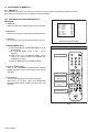
SERVICE MANUAL
COLOUR TELEVISION
7
2006
YA085C
AV-29QT4SU/D
1
4
7
2
3
5
6
8
9
0
ZOOM
PICTURE
P
AV
MENU
P
?
VCR
DVD
RM-C1512
TV
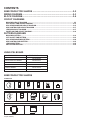
TABLE OF CONTENTS
1
2
3
4
5
PRECAUTION. . . . . . . . . . . . . . . . . . . . . . . . . . . . . . . . . . . . . . . . . . . . . . . . . . . . . . . . . . . . . . . . . . . . . . . . . 1-3
SPECIFIC SERVICE INSTRUCTIONS . . . . . . . . . . . . . . . . . . . . . . . . . . . . . . . . . . . . . . . . . . . . . . . . . . . . . . 1-3
DISASSEMBLY . . . . . . . . . . . . . . . . . . . . . . . . . . . . . . . . . . . . . . . . . . . . . . . . . . . . . . . . . . . . . . . . . . . . . . . 1-4
ADJUSTMENT . . . . . . . . . . . . . . . . . . . . . . . . . . . . . . . . . . . . . . . . . . . . . . . . . . . . . . . . . . . . . . . . . . . . . . . . 1-8
TROUBLESHOOTING . . . . . . . . . . . . . . . . . . . . . . . . . . . . . . . . . . . . . . . . . . . . . . . . . . . . . . . . . . . . . . . . . 1-17
COPYRIGHT © 2006 Victor Company of Japan, Limited
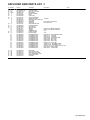
No.YA085C
2006/7
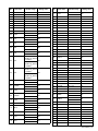
SPECIFICATION
Item
Content
Dimensions ( W × H × D )
78.5cm × 61.5cm × 50cm
Mass
41.1kg
TV RF System
Colour System
B/G, D/K, I, L/L'
TV Mode PAL / SECAM
Video Mode PAL / SECAM / NTSC 3.58 / NTSC 4.43
Sound System
A2 (B/G, D/K), NICAM (B/G, D/K, I, L/L')
Teletext System
Fastext / TOP
Tuning System
Frequency synthesizer tuning system
Receiving Frequency
Intermediate Frequency
Colour Sub Carrier Frequency
VHF(VL)
VHF(VH)
UHF
CATV
46.25MHz - 168.25MHz
175.25MHz - 463.25MHz
471.25MHz - 863.25MHz
S01 - S41
VIF 38.9MHz (B/G, D/K, L) / 33.9MHz (L')
SIF 33.4MHz (5.5MHz:B/G) / 32.9MHz (6.0MHz:I) /
32.4MHz (6.5MHz:D/K, L) / 40.4MHz (6.5MHz:L')
PAL 4.43MHz
SECAM 4.40625MHz / 4.43MHz
NTSC 3.58MHz / 4.43MHz
Power Input
AC220V - AC240V, 50Hz
Power Consumption
130W (Max) / 3W (Standby)
Aerial Input Terminal
75Ω unbalanced, coaxial
Picture Tube Size
Visible size : 68cm (29”), Measured diagonally (H: 54.1cm × V: 40.6cm)
High Voltage
30.0kV (at zero bean current)
Speaker
5.7cm × 12.6cm, Oval type × 2 / 5.1cm Round type (tweeter) × 2
Audio Output
10W + 10W (THD10%)
EXT-1 Input / Output
21-pin Euro connector (SCRAT socket) × 1
EXT-2 Input / Output
EXT-3 Input
21-pin Euro connector (SCRAT socket) × 1
Video 1V(p-p) 75Ω, RCA pin jack × 1
Audio (L/R) 500mV(rms) (-4dBs), High Impedance, RCA pin jack × 2
Headphone jack
Stereo mini jack 3.5mm
Remote Control Unit
RM-C1512 (AA/R06 dry battery × 2)
Design & specifications are subject to change without notice.
1-2 (No.YA085C)
SECTION 1
PRECAUTION
Please refer to "AV-29QT4SU/A (No.YA085)" about this section.
SECTION 2
SPECIFIC SERVICE INSTRUCTIONS
Please refer to "AV-29QT4SU/A (No.YA085)" about this section except a written item.
2.1
Supplementary
AV-29QT4SU/D is the models whose picture tube and some PWB were changed based on AV-29QT4SU/A.
Therefore, this service manual describes only the items which differ from those of the AV-29QT4SU/A service manual.
For details other than those described in this manual, please refer to the AV-29QT4SU/A service manual(No.YA085, 2005/2).
2.2
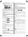
HOW TO IDENTIFY NEW MODELS
"Distinguish name" is added at the bottom of the Rating label.
xxxxxxx xx
DISTINGUISH NAME
DF
2.3
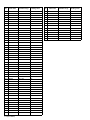
DIFFERENCE LIST
SPECIFICATION
Content
Item
AV-29QT4SU/A
AV-29QT4SU/D
Mass
41.7kg
41.1kg
High Voltage
31.2kV
30.0kV
USING P.W.BOARD
P.W.B ASS'Y Name
MAIN P.W.B
AV-29QT4SU/A
VE-20161071
AV-29QT4SU/D
DESCRIPTION
VE-20265029
CRT SOCKET P.W.B
VE-20173278
VE-20247134
AV & HEADHPONE P.W.B
VE-20166292
VE-20226778
POWER SWITCH P.W.B
VE-20160993
VE-20209386
(No.YA085C)1-3
SECTION 3
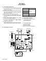
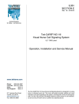
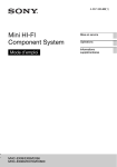
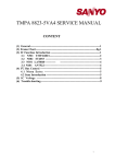
DISASSEMBLY
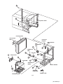
3.1
DISASSEMBLY PROCEDURE
3.1.1
(1)
(2)
(3)
(4)
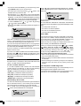
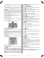
REMOVING THE REAR COVER
Unplug the power cord.
Remove the 8 screws [A].
Remove the 4 screw [B].
Withdraw the REAR COVER toward you.
3.1.2 REMOVING THE BACK DOOR
• Remove the REAR COVER.
(1) Remove the 2 screws [C].
(2) Withdraw the BACK DOOR toward you.
3.1.3 REMOVING THE CHASSIS
• Remove the REAR COVER.
(1) Slightly raise the both sides of the CHASSIS FRAME by hand.
(2) Withdraw the CHASSIS FRAME backward.
(If necessary, take off the wire clamp, connectors etc.)
3.1.4 REMOVING THE MAIN PWB
• Remove the REAR COVER.
• Remove the BACK DOOR.
• Remove the CHASSIS.
(1) Remove the 6 screws [D].
(2) Remove the MAIN PWB.
[CAUTION]
If necessary, take off the wire clamp, connectors etc.
Be careful enough when developing the MAIN PWB.
3.1.5 REMOVING THE SIDE CONTROL PWB
• Remove the REAR COVER.
(1) Remove the 2 screws [E].
(2) Remove the SIDE CONTROL PWB.
3.1.6 REMOVING THE AV & HEADPHONE PWB
• Remove the REAR COVER.
(1) Remove the 1 screws [F].
(2) Remove the AV & HEADPHONE PWB.
3.1.7 REMOVING THE POWER SW PWB
• Remove the REAR COVER.
• Remove the CHASSIS.
(1) Remove the 2 screws [G].
(2) Remove the POWER SW PWB.
3.1.8 REMOVING THE LED PWB
• Remove the REAR COVER.
• Remove the CHASSIS.
• Remove the POWER SW PWB.
(1) Remove the 2 screws [H].
(2) Remove the LED PWB.
3.1.9 REMOVING THE MAIN SPEAKER & TWEETER
• Remove the REAR COVER.
• Remove the CHASSIS.
(1) Remove the 4 screws [J].
(2) Remove the MAIN SPEAKER.
(3) Remove the 2 screws [K].
(4) Remove the TWEETER.
(5) Remove the opposite side similarly.
1-4 (No.YA085C)
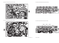
3.1.10 CHECKING THE PW BOARD
• To check the back side of the PW Board.
(1) Pull out the PW Board. (Refer to REMOVING THE MAIN
PWB).
(2) Erect the PW Board vertically so that you can easily check
the back side of the PWB.
[CAUTION]
• When erecting the PW Board, be careful so that there will be
no contacting with other PW Board.
• Before turning on power, make sure that the wire connector
is properly connected.
• When conducting a check with power supplied, be sure to
confirm that the CRT EARTH WIRE (BRAIDED ASS'Y) is
connected to the CRT SOCKET PWB.
3.1.11 WIRE CLAMPING AND CABLE TYING
(1) Be sure to clamp the wire.
(2) Never remove the cable tie used for tying the wires
together.
Should it be inadvertently removed, be sure to tie the wires
with a new cable tie.
A
B
REAR COVER
PICTURE TUBE
CRT SOCKET
PWB
FUNCTION
BUTTON
F
SIDE CONTROL
PWB
AV &
HEADPHONE
PWB
E
POWER SW
PWB
G
C
LED PWB
K
BACK DOOR
D
H
MAIN PWB
J
SPEAKER
(MAIN)
FRONT CABINET
K
SPEAKER
(TWEETER)
POWER CORD
CHASSIS FRAME
Fig.1
(No.YA085C)1-5
3.2
REPLACEMENT OF MEMORY IC
3.2.1 MEMORY IC
This model use a memory IC. This memory IC stores data for proper operation of the video and deflection circuits.
When replacing, be sure to use an IC containing this (initial vaue)data.
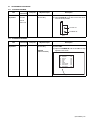
3.2.2 PROCEDURE FOR REPLACING MEMORY IC
PROCEDURE
1. Power off
Switch the power off and unplug the power cord from the outlet.
2. Replace IC.
Be sure to use memory IC written with the initial data values.
3. Power on
Plug the power cord into the outlet and switch the power on.
AK49-0.0.104-JVC-GRA
000
224 SAVEFS
000
225 LOADFS
079
226 DCXO
OFF
227 DCXOA
OFF
001 FAPS
OFF
002 ISPM
OFF
003 INIT
001
005 AGCSPD
006 AGCTO
033
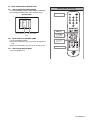
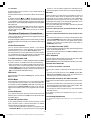
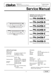
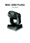
SERVICE MODE SCREEN
Fig.1
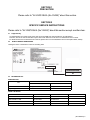
4. SERVICE MENU setting
(1) Press [MUTING] key and [INFORMATION] key at the
simultaneously.
(2) The SERVICE MENU screen of Fig. 1 will be
displayed.
(3) Verify what to set in the SERVICE MENU, and set
whatever is necessary. Refer to the SERVICE ADJUSTMENT for setting.
(4) Press the [MENU] key to exit SERVICE MENU.
5. Receive channel setting
Refer to the OPERATING INSTRUCTIONS (USER'S
GUIDE) and set the receive channels (Channels Preset) as
described.
6. User settings
Check the user setting items according to after page.
Where these do not agree, refer to the OPERATING
INSTRUCTIONS (USER'S GUIDE) and set the items as
described.
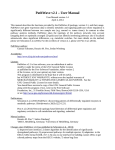
SERVICE MENU SELECT KEY
MUTING key
MENU key
UP / DOWN
[ ]/[ ] key
LEFT / RIGHT
[ ]/[ ] key
INFORMATION key
Fig.2
1-6 (No.YA085C)
3.2.3 SETTINGS OF FACTORY SHIPMENT
3.2.3.1
BUTTON OPERATION
Setting item
3.2.3.2
REMOTE CONTROL DIRECT OPERATION
Setting item
Setting position
Setting position
POWER
Off
CHANNEL
PR1
CHANNEL
PR1
ZOOM
AUTO
Hyper Sound
OFF
3.2.3.3
REMOTE CONTROL MENU OPERATION
(1) PICTURE
(3) FEATURE
Setting item
Setting position
Setting item
Setting position
PICTURE MODE
BRIGHT
SLEEP TIMER
OFF
COLOUR TEMP
COOL
CHILD LOCK
OFF
VNR
AUTO
LANGUAGE
ENGLISH
VCR MODE
OFF
EXT-2 OUTPUT
TV
BLUE BACK
ON
(2) SOUND
Setting item
Setting position
BALANCE
CENTRE
SOUND MODE
STEREO
(4) INSTALLATION
Setting item
Setting position
COLOUR SYSTEM
AUTO
DECODER (EXT2)
ON
FINE TUNING
CENTRE
(No.YA085C)1-7
SECTION 4
ADJUSTMENT
4.1
ADJUSTMENT PREPARATION
(1) You can make the necessary adjustments for this unit with
either the Remote Control Unit or with the adjustment tools
and parts as given below.
(2) Adjustment with the Remote Control Unit is made on the
basis of the initial setting values, however, the new setting
values which set the screen to its optimum condition may
differ from the initial settings.
(3) Make sure that AC power is turned on correctly.
(4) Turn on the power for set and test equipment before use,
and start the adjustment procedures after waiting at least
30 minutes.
(5) Unless otherwise specified, prepare the most suitable
reception or input signal for adjustment.
(6) Never touch any adjustment parts which are not specified
in the list for this adjustment - variable resistors,
transformers, condensers, etc.
(7) Presetting before adjustment.
Unless otherwise specified in the adjustment instructions,
preset the following functions with the remote control unit:
Setting item
Setting value
BRIGHTNESS
CONTRAST
CENTRE
COLOUR
SHARPNESS
COLOUR TEMP
NORMAL
ZOOM
AUTO
4.2
MEASURING EQUIPMENT
(1) Signal generator (Pattern generator)
[PAL / SECAM / NTSC]
(2) Remote control unit
4.3
ADJUSTMENT ITEM
• FOCUS ADJUSTMENT
• SCREEN ADJUSTMENT
• DEFLECTION CIRCUIT ADJUSTMENT
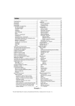
4.4
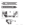
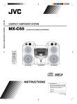
ADJUSTMENT LOCATIONS
LED PWB
(SOLDER SIDE)
LED
POWER SW PWB
IR RECEIVER
POWER SW
FRONT
TOP
FUSE
SIDE CONTROL
PWB
PL107
POWER CORD
MAIN PWB
TOP
FRONT
MENU
PL800
P/Ch
PL404
TOP
AV &
HEADPHONE
PWB
HEADPHONE
PFC COIL
PL801
PL101
PL401
DEG COIL
PL802
PL103
PL102
MEMORY
PL105
IC101
DEF YOKE
PL602
PL106
VIDEO
PL107
L
PL104
R
PL603
FBT
PL105
PL115
TUNER
FRONT
TU100
PL605
EXT-1(SCART)
EXT-2(SCART)
SPEAKER
R
SPEAKER
L
PL116
UPPER : FOCUS
LOWER : SCREEN
PL902
TOP
PL901
CRT SOCKET PWB
(SOLDER SIDE)
1-8 (No.YA085C)
4.5
BASIC OPERATION OF SERVICE MODE
4.5.1 HOW TO ENTER THE SERVICE MODE
(1) Press the [INFORMATION] key and [MUTING] key simultaneously.
(2) The SERVICE MENU screen will be displayed.(Fig.1)
SERVICE MENU
SERVICE MENU SELECT KEY
MUTING key
AK49-0.0.104-JVC-GRA
000
224 SAVEFS
000
225 LOADFS
079
226 DCXO
OFF
227 DCXOA
OFF
001 FAPS
OFF
002 ISPM
OFF
003 INIT
001
005 AGCSPD
006 AGCTO
033
MENU key
ADJUSTMENT ITEM
SETTING VALUE
Fig.1
4.5.2 SELECTION OF ADJUSTMENT ITEMS
(1) Enter the SERVICE MODE
(2) Press the FUNCTION []/[] key to select the adjustment
item.
(3) Press the FUNCTION []/[] key to set the setting value.
4.5.3 HOW TO EXIT SERVICE MODE
(1) Press the [MENU] key.
UP / DOWN
[ ]/[ ] key
LEFT / RIGHT
[ ]/[ ] key
INFORMATION key
(No.YA085C)1-9
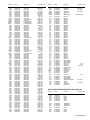
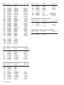
4.6
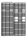
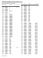
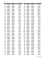
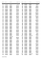
INITIAL SETTING VALUES IN THE SERVICE MODE
Item
No.
Item name
Variable range
Setting value
Item
No.
Item name
Variable range
000 - 015
Setting value
001 FAPS
---
---
049 YSCM
012
002 ISPM
ON/OFF
OFF
050 YNTS
000 - 015
002
000 - 015
012
003 INIT
ON/OFF
OFF
051 YPAL
005 AGCSPD
000 - 003
001
052 YAV1
000 - 015
012
000 - 015
012
006 AGCTO
000 - 063
033
053 YAV2
007 COFF
---
---
054 Y_S1
000 - 015
012
055 Y_S2
000 - 015
012
008 VSD
000 - 063
031
009 VG2
000 - 063
031
010 TUBE
000 = 16:9
001 = 4:3
056 COMB
001
058 BLCS
000 = Not active
001 = Active
000 = Disable
001 = Enable
000
000
011 VERT ZOOM
000 - 063
035
012 VERT SLOP
000 - 063
037
013 VERT SHIFT
000 - 063
025
014 VERT AMP
000 - 063
033
060 WHTS
000 - 003
000
015 SCORRECTION 000 - 063
032
061 CLPR
000 - 003
000
016 V-LINC
000
062 OVSH
000 - 003
000
000 - 063
032
000 - 002
059 BLUS
000 = Disable
001 = Enable
000
017 V-LINEARTY
000 - 063
032
063 TNTD
018 EW WIDTH
000 - 063
018
064 SVMA
ON/OFF
OFF
065 SVM
000 - 007
004
019 HOR SHIFT
000 - 063
031
020 EW PARAB
000 - 063
035
021 TRAPEZ
000 - 063
030
022 UC PARAB
000 - 063
013
023 LC PARAB
000 - 063
016
003:1.8 Vp-p
024 HOR BOW
000 - 063
042
000:OFF
025 PARALLEL
000 - 063
033
026 WBF
000 - 015
014
027 WBR
000 - 015
010
028 WBF14
000 - 015
014
068 SOPW
000 - 003
003
000 - 007
007
000:OFF
066 VMA
067 SMD
001:0.8 Vp-p
002:1.2 Vp-p
001:Video
002:TXT/OSD
001
001
003:Video/OSD
029 WBR14
000 - 015
013
069 SOTM
030 60HZ EWW
000 - 063
034
070 WPRC
000 - 063
032
000 - 063
032
031 60HZ HSH
000 - 063
037
071 WPGC
032 60HZ VSH
000 - 063
031
072 WPBC
000 - 063
031
000 - 063
033
033 60HZ VZ
000 - 063
035
073 BLORC
034 ROT
000 - 063
049
074 BLOGC
000 - 063
033
000 - 063
037
035 ROT-M
000 - 001
000
075 WPRN
036 OIF
000 - 063
032
076 WPGN
000 - 063
032
000 - 063
019
037 IF
000 - 007
002
077 WPBN
038 OFR
000 - 001
000
078 BLRB-RGB
000 - 063
033
000 - 063
033
039 FFI
000 - 001
000
079 BLG-RGB
040 BS1
000 - 015
001
080 WPRW
000 - 063
049
000 - 063
040
041 BS2
000 - 015
002
081 WPGW
042 BS3
000 - 015
008
082 WPBW
000 - 063
025
000 - 063
033
043 CB
000 - 255
142
083 BLRB-YUV
044 B1-H
000 - 255
011
084 BLG-YUV
000 - 063
033
000 - 063
032
045 B1-L
000 - 255
082
085 WPR-RGB
046 B2-H
000 - 255
030
086 WPG-RGB
000 - 063
040
000 - 063
032
ON/OFF
ON
047 B2-L
000 - 255
002
087 WPB-RGB
048 FRAV
000 - 003
001
088 OSO
1-10 (No.YA085C)
Item
No.
Item name
Variable range
Setting value
Item
No.
Item name
Variable range
Setting value
089 FSL
000 - 001
000
090 MUS
ON/OFF
OFF
091 PWL
000 - 015
000
118 ---
092 BPS
ON/OFF
OFF
119 V-3D
000 - 063
000
093 CLPL
000 - 003
000
120 ---
---
000
117 OPEQ
000 = Disable
001 = Enable
---
000
000
094 CL
000 - 015
000
121 ODUB
000 - 005
000
095 AKB
ON/OFF
OFF
122 AVLL
000 - 015
002
096 COR
000 - 003
002
123 AVLW
000 - 001
000
098 SSL
000 - 001
001
124 AVLM
000 - 005
003
125 OPAVL
000 - 001
000
126 AVL
000 - 001
001
127 DECL
000 - 031
015
128 MNLV
000 - 031
015
129 ADCAM
000 - 031
010
130 ADCAV
000 - 031
013
099 AV2SI
100 AV3I
101 FAVI
102 BAVI
103 VESI
104 FSVI
105 BSVI
106 DVDI
000 = Disable
001 = Enable
000 = Disable
001 = Enable
000 = Disable
001 = Enable
000 = Disable
001 = Enable
000 = Disable
001 = Enable
000:Disable Front
SVHS if Op_SVHS
is enabled
001:Enable Front
SVHS if Op_SVHS
is enabled
000:Disable Back
SVHS if Op_SVHS
is enabled
001:Disable Back
SVHS if Op_SVHS
is enabled
000 = Disable
001
000
001
000
000
108 SSTDI
109 SSTDDK
110 SSTDL
111 NICAM
000 = Disable
001 = Enable
000 = Disable
001 = Enable
000 = Disable
001 = Enable
000 = Disable
001 = Enable
ON/OFF
000
000
000
001
001 = AV-Stereo
114 BLNG
116 OPHP
ON/OFF
000 = Disable
001 = Enable
000 = Disable
001 = Enable
046
133 AV2 PRESCL
000 - 063
046
134 E2D
ON/OFF
OFF
000 = Full screen
001 = Split screen
000
136 TXHPOS
000 - 063
000
137 TXEWW
000 - 063
048
138 TXHPA
000 - 063
000
139 TXHPB
000 - 063
000
140 TXHBB
000 - 127
073
141 PATVA
000 - 063
016
142 PATVZ
000 - 063
016
143 PATPARAB
000 - 063
016
144 PATHS
000 - 063
032
145 TXTBRI
000 - 063
032
146 ---
---
OFF
147 TXTCON
000 - 015
010
148 LSEL-1
000 - 255
255
149 LSEL-2
000 - 031
031
001
150 PWPRF
001
151 PWRES
ON
152 MAXCOL
000 - 063
045
153 MAXBRI
000 - 063
045
002
154 MAXCON
000 - 063
028
155 PVBRSP
000 - 063
032
ON
156 PVCTSP
000 - 063
032
157 PVCLSP
000 - 063
032
000
158 PVSHSP
000 - 063
032
159 PVBRMV
000 - 063
032
002 = Stereo
113 CMUTE
015
000 - 063
001
000 = Mono
112 CNFG
000 - 031
132 AV1 PRESCL
135 TXSPLT
001 = Enable
107 SSTDBG
131 NICL
000
000 = Fast
015 = Perfect
000 = Disable
001 = Enable
015
001
160 PVCTMV
000 - 063
032
161 PVCLMV
000 - 063
032
(No.YA085C)1-11
Item
No.
Item name
Variable range
162 PVSHMV
000 - 063
163 PVBRWK
164 PVCTWK
Setting value
Item
No.
Item name
Variable range
Setting value
032
214 OFB
000 - 063
001
000 - 063
032
215 PGR
000 - 127
070
000 - 063
032
216 PGG
000 - 127
080
165 PVCLWK
000 - 063
032
217 PGB
000 - 127
070
166 PVSHWK
000 - 063
032
218 REMOTE
---
---
167 PABAMM
000 - 063
031
219 PIPPAP
---
---
168 PATRMM
000 - 063
015
220 CABINE
---
---
169 PAB1MM
000 - 063
042
221 ZOOME
---
---
170 PAB2MM
000 - 063
058
222 ---
---
---
171 PAB3MM
000 - 063
045
223 ---
---
---
172 PAB4MM
000 - 063
040
224 SAVEFS
000 - 001
000
173 PAB5MM
000 - 063
058
225 LOADFS
000 - 001
000
174 PABAMU
000 - 063
039
226 DCXO
000 - 127
079
175 PATRMU
000 - 063
034
227 DCXOA
ON/OFF
OFF
176 PAB1MU
000 - 063
040
177 PAB2MU
000 - 063
050
178 PAB3MU
000 - 063
055
179 PAB4MU
000 - 063
060
180 PAB5MU
000 - 063
063
181 PABATH
000 - 063
034
182 PATRTH
000 - 063
036
183 PAB1TH
000 - 063
030
184 PAB2TH
000 - 063
055
185 PAB3TH
000 - 063
063
186 PAB4TH
000 - 063
050
187 PAB5TH
000 - 063
040
188 PABASP
000 - 063
034
189 PATRSP
000 - 063
036
190 PAB1SP
000 - 063
036
191 PAB2SP
000 - 063
044
192 PAB3SP
000 - 063
044
193 PAB4SP
000 - 063
040
194 PAB5SP
000 - 063
024
198 CTI1
000 - 255
032
199 CTI2
000 - 255
008
200 CTI3
000 - 255
228
201 P BS1
000 - 015
001
202 P BS2
000 - 015
002
203 P BS3
000 - 015
004
204 P CB
000 - 255
142
205 P B1H
000 - 255
012
206 P B1L
000 - 255
032
207 P B2H
000 - 255
030
208 P B2L
000 - 255
002
209 P BRI
000 - 015
007
210 P CON
000 - 015
010
211 P AGC
000 - 255
023
212 P YPAL
000 - 015
000
213 P YSCM
000 - 015
000
1-12 (No.YA085C)
4.7
ADJUSTMENTS PROCEDURE
4.7.1 FOCUS ADJUSTMENT
Item
FOCUS
adjustment
Measuring
instrument
Test point
Signal
generator
Adjustment part
FOCUS VR
[On the FBT]
Description
(1) Receive a crosshatch signal.
(2) Adjust FOCUS VR on the FBT for the lines to become as thin as possible.
Remote
control unit
FOCUS VR
SCREEN VR
FBT
4.7.2 SCREEN ADJUSTMENT
Item
SCREEN
adjustment
Measuring
instrument
Remote
control unit
Test point
Adjustment part
SCREEN VR
[On the FBT]
009 VG2
[SERVICE MODE]
Description
(1) Enter the SERVICE MODE.
(2) Select VG2.
(3) Adjust the SCREEN VR until the "STABLE IN" sign
appears on the screen.
AK49-0.0.104-JVC-GRA
005 AGCSPD
001
006 AGCTO
033
007 COFF
025
008 VSD
031
009 VG2
031
010 TUBE
001
011 VERT ZOOM
035
012 VERT SLOP
037
025
013 VERT SHIFT
STABLE IN
Appears
(No.YA085C)1-13
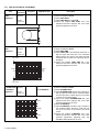
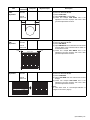
4.7.3 DEFLECTION CIRCUIT ADJUSTMENT
Measuring
instrument
Item
VERTICAL
SHIFT
adjustment
Signal
generator
Test point
Adjustment part
013 VERT SHIFT
Remote
control unit
Description
(1)
(2)
(3)
(4)
(5)
Receive a circle pattern signal.
Enter the SERVICE MODE.
Select VERT SHIFT.
Adjust VERT SHIFT to make A=B.
Check and readjust VERT SHIFT item if the
adjustment becomes improper after some other
geometric adjustments are done.
A
B
VERTICAL
SIZE
adjustment
Signal
generator
014 VERT AMP
Remote
control unit
Very close
(1)
(2)
(3)
(4)
Receive a crosshatch signal.
Enter the SERVICE MODE.
Select VERT AMP.
Adjust VERT AMP until horizontal black lines on
both the upper and lower part of the crosshatch
pattern become very close to the upper and lower
horizontal sides of picture size and nearly about to
disappear.
(5) Check and readjust VERT AMP item if the
adjustment becomes improper after some other
geometric adjustments are done.
Picture
size
100%
Screen
size
Very close
VERTICAL
Signal
S-CORRECTION generator
& LINEARITY
adjustment
Remote
control unit
015 SCORRECTION
017 V-LINEARITY
(1)
(2)
(3)
(4)
(5)
UPPER
(6)
(7)
CENTRE
(8)
LOWER
1-14 (No.YA085C)
Receive a crosshatch signal.
Enter the SERVICE MODE.
Select SCORRECTION.
Adjust SCORRECTION until the size of squares on
both the upper and lower part of crosshatch pattern
become equal to the squares laying on the vertical
centre of the crosshatch pattern.
Check and readjust SCORRECTION item if the
adjustment becomes improper after some other
geometric adjustments are done.
Select V-LINEARITY.
Adjust V-LINEARITY until all the size of squares of
the crosshatch pattern become in equal size from
the top of the screen to its bottom of the whole
screen.
Check and readjust V-LINEARITY item if the
adjustment becomes improper after some other
geometric adjustments (especially after than
SCORRECTION adjustment) are done.
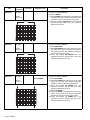
Measuring
instrument
Item
HORIZONTAL
SHIFT
adjustment
Test point
Adjustment part
Signal
generator
019 HOR SHIFT
(1)
(2)
(3)
(4)
(5)
018 EW WIDTH
(1)
(2)
(3)
(4)
Remote
control unit
C
HORIZONTAL
SIZE
adjustment
D
Signal
generator
Remote
control unit
Very
close
Description
Screen size
Very
close
Receive a circle pattern signal.
Enter the SERVICE MODE.
Select HOR SHIFT.
Adjust HOR SHIFT to make C=D.
Check and readjust HOR SHIFT item if the
adjustment becomes improper after some other
geometric adjustments are done.
Receive a crosshatch signal.
Enter the SERVICE MODE.
Select EW WIDTH.
Adjust EW WIDTH until no white bars on both the left
and right sides of the crosshatch will be visible nor
screen will be so wide.
(5) Check and readjust EW WIDTH item if the
adjustment becomes improper after some other
geometric adjustments are done.
Picture size 100%
BOW
adjustment
Signal
generator
Remote
control unit
024 HOR BOW
(1)
(2)
(3)
(4)
Receive a crosshatch signal.
Enter the SERVICE MODE.
Select HOR BOW.
Adjust HOR BOW until the vertical lines become
straight.
(5) Check and readjust HOR BOW item if the
adjustment becomes improper after some other
geometric adjustments are done.
NOTE :
In case where there is a bow-shaped distortion of
images on the screen. (Figure)
(No.YA085C)1-15
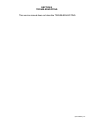
Item
TRAPEZIUM
adjustment
Measuring
instrument
Test point
Signal
generator
Adjustment part
021 TRAPEZ
Receive a crosshatch signal.
Enter the SERVICE MODE.
Select TRAPEZ.
Adjust TRAPEZ until vertical lines, especially lines at
the sides of the picture frame become parallel to the
both sides of picture tubes as close as possible.
(5) Check and readjust TRAPEZ item if the adjustment
becomes improper after some other geometric
adjustments are done.
020 EW PARAB
(1)
(2)
(3)
(4)
022 UC PARAB
(1)
(2)
(3)
(4)
Remote
control unit
Parallel
SIDE PIN
adjustment
Signal
generator
Remote
control unit
Straight
CORNER
adjustment
Signal
generator
023 LC PARAB
Remote
control unit
Straight
Description
Straight
(1)
(2)
(3)
(4)
Receive a crosshatch signal.
Enter the SERVICE MODE.
Select EW PARAB.
Adjust EW PARAB until vertical lines close to the
both sides of the picture frame become straight to
vertical sides of picture tube without any bending to
left or to right side of the screen.
(5) Check and readjust EW PARAB item if the
adjustment becomes improper after some other
geometric adjustments are done.
(5)
(6)
(7)
(8)
1-16 (No.YA085C)
Receive a crosshatch signal.
Enter the SERVICE MODE.
Select UC PARAB.
Adjust UC PARAB until vertical lines at the upper
corners of the picture frame become vertical and
parallel to vertical corner sides of picture tube.
Check and readjust UC PARAB item if the
adjustment becomes improper after some other
geometric adjustments are done.
Select LC PARAB.
Adjust LC PARAB until vertical lines at the lower
corners of the picture frame become vertical and
parallel to vertical corner sides of picture tube.
Check and readjust LC PARAB item if the
adjustment becomes improper after some other
geometric adjustments are done.
SECTION 5
TROUBLESHOOTING
This service manual does not describe TROUBLESHOOTING.
(No.YA085C)1-17
Victor Company of Japan, Limited
Display Category 12, 3-chome, Moriya-cho, Kanagawa-ku, Yokohama-city, Kanagawa-prefecture, 221-8528, Japan
(No.YA085C)
Printed in Japan
VPT
Color profile: Disabled
Composite Default screen
ENGLISH
FRANÇAIS
NEDERLANDS
CASTELLANO
DEUTSCH
ITALIANO
PORTUGUÊS
AV-29QT4BU
AV-29QT4SU
COLOUR TELEVISION
TELEVISEUR COULEUR
KLEURENTELEVISIE
TELEVISOR A COLOR
FARBFERNSEHGERÄT
TELEVISORE A COLORI
TELEVISOR A CORES
50086700
©2006 Victor Company of Japan, Limited
0506TKH-VT-VT
D:\IB Guncel\JVC AK49\2929 (AV-29QT4SU) (1512 UK) (10041580)\A-COVER PAGE-AK49-C1512UK-2929-RF-CLED-PLLCH-(AV-29QT4SU)-10041580-50086700.cdr
17 Mayıs 2006 Çarşamba 14:54:05
INSTRUCTIONS
MANUEL D'INSTRUCTIONS
GEBRUIKSAANWIJZING
MANUAL DE INSTRUCCIONES
BEDIENUNGSANLEITUNG
ISTRUZIONI
INSTRUÇÕES
Contents
Safety Precautions
Safety Precautions .................................................. 1
1. Power Source
Remote Control Buttons ......................................... 2
The receiver should be operated only from a 220-240V AC,
50 Hz. outlet. Ensure you select the correct voltage setting for
your convenience.
TV Buttons and Functions and Rear Panel .......... 3
Antenna Connections.............................................. 3
Preparation ............................................................... 4
Features .................................................................... 4
Before Switching on your TV ................................. 4
Power connection ...........................................................
Connections to the RF input socket ................................
How to connect other devices .........................................
Inserting batteries into the remote control .......................
4
4
4
4
Switching the TV ON/OFF ....................................... 4
To switch the TV on ........................................................ 4
To switch the TV off ......................................................... 4
Initial Settings .......................................................... 4
T-V LINK ......................................................................... 5
Basic Operations ..................................................... 6
Setting the TV .......................................................... 6
Picture Menu ..................................................................
Sound Menu ...................................................................
Feature Menu .................................................................
Installation Menu .............................................................
Programme Menu ...........................................................
6
7
8
8
9
Other Features ...................................................... 10
2. Power Cord
The power supply cord should be placed so that they are not
likely to be walked on or pinched by items placed upon them
or against them. Pay particular attention to cord where they
enter the plug, power outlet, and the point where they exit
from the receiver.
3. Moisture and Water
Do not use this equipment in a humid and damp place (avoid
the bathroom, the sink in the kitchen, and near the washing
machine). Do not expose this equipment to rain or water and
do not place objects filled with liquids on it as this may be
dangerous.
4. Cleaning
Before cleaning, unplug the receiver from the main supply outlet. Do not use liquid or aerosol cleaners. Use with soft and
dry cloth.
5. Ventilation
The slots and openings on the receiver are intended for ventilation and to ensure reliable operation. To prevent overheating,
these openings must not be blocked or covered in anyway.
6. Lightning
Teletext ................................................................... 11
In case of storm and lightning or when going on holiday, disconnect the power cord from the wall outlet.
Peripheral Equipment Connections .................... 12
7. Replacement Part
Tips .......................................................................... 14
When replacement parts are required, be sure the service technician has used replacement parts which are specified by the
manufacturer or have the same specifications as the original
one. Unauthorized substitutions may result in fire, electrical
shock, or other hazards.
Specifications ........................................................ 14
8. Servicing
Please refer all servicing to qualified personnel. Do not remove
cover as this may result in electric shock.
9. Flame sources
Do not place naked flame sources on the apparatus.
10. Stand-By
Do not leave your TV stand-by or operating condition when
you leave your house.
Warning!
Any intervention contrary to regulations, in particular, any modification of high voltage or a replacement of the picture tube
may lead to an increased concentration of x-rays. Any television modified in this way no longer complies with license and
must not be operated.
Instructions for waste disposal:
Packaging and packaging aids are recyclable and should principally be recycled. Packaging materials, such as foil bag,
must be kept away from children.
Batteries, including those which are heavy metal-free, should
not be disposed of with household waste. Please dispose of
used batteries in an environmentally sound manner. Find out
about the legal regulations which apply in your area.
-1A01-ENG&AK49-C1512UK-2929-RF-CLED-PLLCH-(AV-29QT4SU)-10041580-50086700.p65
1
18.05.2006, 10:05
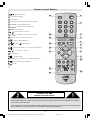
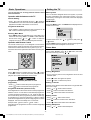
Remote Control Buttons
= Stand By / Power
£
0 - 9 = Direct Program
£
Yellow Button
Blue Button / Factory Settings in Picture Menu
Ó
PICTURE = Picture Mode Change
(
) = Programme Up (Cursor Up)
MENU = Menu Button
(
) = Cursor Right / Volume +
(
) = Programme Down (Cursor Down)
Teletext / VCR / DVD Control Buttons
£n
Î
£Ç
{
= Stereo / Bilingual Button
= VCR /
= Information Button / T-V Link in Program Menu
(
x
£È
/ DVD Switch
) = Cursor Left / Volume -
È
£x
Ç
£{
n
AV = AV Button
= Teletext Button
£Ç
£n
£
ZOOM = Zoom (Picture Size) Change / Red Button
£ä
= Hyper Sound / Green Button
= Mute
£Î
££
£Ó
CAUTION
RISK OF ELECTRIC SHOCK
The lightning flash with arrowhead symbol, within an equilateral triangle, is intended to alert the user to the presence
of uninsulated "dangerous voltage" within the product's enclosure that may be of sufficient magnitude to constitute a
risk of electric shock of persons.
The exclamation point within an equilateral triangle is intended to alert the user to the presence of important operating
and maintenance (servicing) instructions in the literature accompanying the appliance.
-2A01-ENG&AK49-C1512UK-2929-RF-CLED-PLLCH-(AV-29QT4SU)-10041580-50086700.p65
2
18.05.2006, 10:05
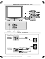
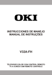
TV Buttons and Functions and Rear Panel
0HQX
+HDGSKRQH
9LGHR,QSXW
3URJUDP
7HUPLQDO
3&K
/
$XGLR,QSXW
7HUPLQDO
5
)5217$9
(;7
9ROXPH
&21752/
3$1(/
%877216
3RZHU
( ; 7 ( ; 7 $QWHQQD
(;7
(;7
Antenna Connections
-3A01-ENG&AK49-C1512UK-2929-RF-CLED-PLLCH-(AV-29QT4SU)-10041580-50086700.p65
3
18.05.2006, 10:05
69+6
Replace the battery cover.
Preparation
Place TV on a solid surface.
For ventilation, leave a space of at least 10 cm free all around
the set. To prevent any fault and unsafe situations, please do
not place any objects on top of the set.
Use this apparatus in tropical and moderate climates.
Features
It is a remote controlled colour television.
100 programmes from VHF, UHF bands or cable channels
can be preset.
It can tune cable channels.
Controlling the TV is very easy by its menu driven system.
It has two Euroconnector sockets for external devices (such
as computer, video, video games, audio set, etc.)
A2+NICAM Stereo sound system.
Teletext (Fastext, Toptext).
It is possible to connect headphone.
Direct channel access.
A.P.S. (Automatic Programming System).
All programmes can be named.
Programme swapping between last watched two programmes.
Forward or backward automatic tuning.
Sleep timer.
Child Lock.
Automatic sound mute when no transmission.
When no valid signal is detected, after 5 minutes the TV
switches itself automatically to stand-by mode.
NTSC Playback.
S-VHS (via SCART)
Real Flat
Before Switching on your TV
Power connection
IMPORTANT: The TV set is designed to operate on 220-240V
AC, 50 Hz.
After unpacking, allow the TV set to reach the ambient room
temperature before you connect the set to the mains.
Connections to the RF input socket
Connect the aerial or cable TV plug to the RF input socket
located at the back of the TV and connect the cable plug
coming out from the TV out socket located at the devices
(VCR, DVB etc.) to this socket as well.
How to connect other devices
IMPORTANT: Switch off the TV before connecting any external device.
Sockets for external connections are at the back and on the
TV. For connection of other devices via Euroconnector refer to
the manuals of the related devices.
NOTE: Remove batteries from remote control when it is not to
be used for a long period. Otherwise it can be damaged due to
any leakage of batteries.
Switching the TV ON/OFF
To switch the TV on
Your TV will switch on in two steps:
1- Press the power button located on the front of the TV. Then
the TV switches itself to standby mode and the power lamp
becomes RED located on the lower part of the TV.
2- To switch on the TV from stand-by mode either:
Press the , button on the remote control,
or,
Press a digit button on the remote control so that a programme
number is selected,
or,
Press Programme Up or Down buttons on the TV or on the
remote control, so that last switched off programme is selected.
The TV will switch on and the power lamp will be GREEN.
To switch the TV off
Press the stand-by button on the remote control, so the TV
will switch to stand-by mode and the power lamp will become RED,
or,
Press the power button located on the front of the TV, so the
TV will switch off and the power lamp will turn off.
Initial Settings
When the TV is first turned on, it goes into the initial settings
mode. Follow the instructions on the screen display to make
the initial settings.
Note: If the TV does not go into the initial settings mode this is because your TV has
already been turned on for the first time. (Perform AUTO STORE (see page 9) in the
PROGRAMME menu.)
Because this is the first time that TV has been used, there are
no channels stored in the memory. Analogue terrestrial broadcasting AUTOMATIC PROGRAMMING SYSTEM (A.P.S.) window is displayed.
$36
3/($6( &+(&. $17(11$ &$%/(
Inserting batteries into the remote control
$8726725(
Remove the battery cover located on the back of the remote
control by gently pulling downwards from the indicated part.
Insert two AA (R06) or equivalent type batteries inside. Place
the batteries in the right directions as seen below.
&28175<
8.
/$1*8$*(
(1*/,6+
&217,18(
-4A01-ENG&AK49-C1512UK-2929-RF-CLED-PLLCH-(AV-29QT4SU)-10041580-50086700.p65
4
18.05.2006, 10:05
If you do not want to start A.P.S., you can cancel it by pressing the MENU button on your remote control.
First select your country by pressing or button. This
will affect the sort process in APS.
By pressing the or buttons, come to the Language
item and select the language in which the menus of the TV
will appear. You can see the available languages by pressing
or button. As soon as you change the language, the
menu items will be displayed in the selected language.
To select Continue use or button. By pressing
or button start the A.P.S.
When you start A.P.S. the following window will appear on
the screen.
$36
$36,65811,1*
3/($6(:$,7
35&+$11(/1$0(
Press button to start downloading data to VCR. TRANSFER is displayed in the menu. Transfer bar can only be seen
after APS.
79/,1.
'2:1/2$' 79 9&5
75$16)(5
If you do not want to continue press the PICTURE button to
exit the menu.
If FEATURE NOT AVAILABLE is displayed, download was
not performed correctly. Before trying to download again, check
that:
The VCR power is turned on.
The VCR is T-V LINK compatible.
The VCR is connected to the EXT.2.
The scart cable is fully wired.
Direct REC:
&&
After APS is finalized, a programme list will appear on the
screen. In the programme list you will see the programme
numbers and names assigned to the programmes.
If you do not accept the locations and / or the programme
names of programmes, you can change them in Program menu.
For details see PROGRAMME menu on page 9.
If you do not have a T-V LINK compatible VCR, press BLUE
button to exit the menu.
If you have a T-V LINK compatible VCR connected to the EXT.2
terminal, press button to display T-V LINK menu. Then
follow the operating procedure Downloading data to VCR in
the following T-V LINK section.
T-V LINK
When a T-V LINK compatible VCR is connected to the EXT.2
terminal on the TV, it is easier to set up the VCR and to view
videos. T-V LINK uses the following features:
To use T-V LINK functions
A T-V LINK compatible VCR means a JVC video cassette
recorder with the T-V LINK logo, or with one of the following
logos. For details see your VCR instruction manual.
Q-LINK (A trademark of Panasonic Corporation)
Data Logic (A trademark of Metz Corporation)
Easy Link (A trademark of Philips Corporation)
Megalogic (A trademark of Grundig Corporation)
SMARTLINK (A trademark of Sony Corporation)
You can easily record to VCR the images that you are watching on the TV. For details, read the manual for your VCR. Use
your VCR controls. VCR IS RECORDING is diplayed. You
can not carry out Direct REC using your TVs control.
When the VCR is not ready (For example when there is no
tape inserted), NO RECORDING is displayed.
When you press the following buttons ( ,, , AV, MENU,
, BACK, SUBTITLE, GUIDE, ZOOM,
,
/
,
number buttons) during recording, a message appears asking
if you want to stop recording or not. Press or button
to stop recording or BLUE button to continue recording.
Do not turn the TV off in the following cases:
When recording images from an external device connected
to TV (For example camcorder).
When recording a TV channel after it has been unscrambled
on a decoder.
When recording a TV channel by using the TVs output because the VCRs own tuner can not properly receive that
channel.
TV autopower on/VCR image view:
When the VCR starts playing, the TV automatically turns on
and images from EXT2 appear on the screen.
This function does not happen if your TVs main power is turned
off. Set your TVs main power to on (StandBy Mode).
Downloading data to VCR:
The VCR will automatically download the registered data on
the TV channels from the TV. This means you do not need to
set up the programme channels on your VCR manually.
The T-V LINK menu will be displayed when you press the
button while PROGRAM menu is displayed.
79/,1.
'2:1/2$' 79 9&5
67$57
3,&785(&$1&(/
-5A01-ENG&AK49-C1512UK-2929-RF-CLED-PLLCH-(AV-29QT4SU)-10041580-50086700.p65
5
18.05.2006, 10:05
Basic Operations
Setting the TV
You can operate your TV using both the remote control
and onset buttons.
Operation with the buttons on the TV
Volume Setting
Press
- button to decrease volume or
+ button to
increase volume, so a volume level scale (slider) will be displayed at the middle of the bottom on the screen.
Programme Selection
Menu System
Your TV has been designed with a menu system, to provide
an easy manipulation of a multi-function system. The TV is
controlled by choosing the commands, which are displayed
on the screen.
MAIN MENU
Press the MENU button. The MENU will be displayed in the
middle on the screen.
0(18
Press P/CH + button to select the next programme or P/
CH - button to select the previous programme.
3,&785(
6281'
)($785(
,167$//$7,21
352*5$00(
Entering Main Menu
Press MENU button to enter Main menu. In the Main menu
select sub-menu using P/CH - or P/CH + button and enter
- or
+ button. To learn the
the sub-menu using
usage of the menus, refer to the Menu System sections.
Operation with Remote Control
The remote control of your TV is designed to control all the
functions of the model you selected. The functions will be described in accordance with the menu system of your TV.
Functions of the menu system are described in following sections.
To select a sub-menu use or button, and press
or button.
Use the MENU button to go back to the previous programme
when the menu does not appear on the screen.
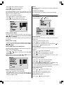
Picture Menu
Press MENU button, now you are in main menu. In the Main
menu, select Picture using or button, then enter
the Picture menu by pressing / .
3,&785(
%5,*+71(66
&2175$67
&2/285
6+$ 531(66
67$1'$5'
&2/2857(03
&22/
915
2))
5(6(7
Volume Setting
Press
+ button to increase volume. Press
- button
to decrease volume. A volume level scale (slider) will be displayed in the middle at the bottom of the screen.
Programme Selection (Previous or next
programme)
Press
Press
3,&785(02'(
Setting Brightness
As you enter the picture menu, Brightness will be the first
selected option.
Press
button to brighten the picture.
Press
button to darken the picture.
Setting Contrast
button to select the previous programme.
button to select the next programme.
Contrast is the difference and distribution of light and dark
tones in an image.
Using or button select Contrast.
Programme Selection (direct access):
Press digit buttons on the remote control to select programmes
between 0 and 9. TV will switch to the selected programme.
To select programmes between 10 - 99, press the digit buttons consecutively which programme you want to select (eg.
for programme 27, first press 2 and then 7). When it is late to
press second digit button only the first digit programme will be
displayed. The limit of the delay time is 3 seconds.
Press button to increase contrast level.
Example: PR6
press 6, PR12
press 1 and 2.
Press directly the programme number to reselect single digit
programmes.
Press button to decrease contrast level.
Setting Colour
Using
or
button select Colour.
Press
button to increase colour saturation.
Press
button to decrease colour saturation.
Setting Sharpness
Using
or
button select Sharpness.
-6A01-ENG&AK49-C1512UK-2929-RF-CLED-PLLCH-(AV-29QT4SU)-10041580-50086700.p65
6
18.05.2006, 10:05
Press
button to sharpen the picture.
Reset
Press
button to soften the picture.
Press BLUE button to reset the picture modes to factory default settings.
Setting Hue (In AV mode only)
(During Playback NTSC system, this will appear in AV mode
only when NTSC video source is applied. Otherwise, HUE
option is invisible in Picture menu.):
Using or button select Hue.
Press
button to increase the green tones.
Press
button to increase the red tones.
To Store the Settings
In the Picture Menu, all settings are stored automatically.
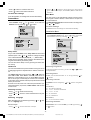
Sound Menu
Press MENU button, now you are in MENU. In the MENU,
select SOUND using or button, then enter the sound
menu by pressing or button.
Center value is indicated with two reciprocal arrows.
0(18
3,&785(
6281'
)($785(
,167$//$7,21
352*5$00(
3,&785(
&2175$67
&2/285
6+$ 531(66
+8(
3,&785(02'(
67$1'$5'
&2/2857(03
&22/
915
$872
9&502'(
2))
6281'
92/80(
5(6(7
%$/$1&(
6281'02'(
Setting Picture Mode
0212
%$66
75(%/(
This item is used to change the picture mode. By pressing
or button you may select one of these options: STANDARD, SOFT and BRIGHT.
You can also set the Picture Mode by pressing the Blue button directly.
Setting Volume
Setting Colour Temp
Press button to increase volume.
This item is used for white colour tint adjustment. By pressing
or button you may select one of these options: COOL,
NORMAL, WARM.
Press button to decrease volume.
Setting VNR (Video Noise Reduction)
Setting Balance
This item is used to reduce the image noise and improve the
picture quality at weak signals.
Using or button select VNR.
It allows adjusting the distribution between the left and right
speakers.
Using or button select Balance.
Press or button to set VNR level to OFF, MIN,
AUTO or MAX.
AUTO adjusts the VNR level to OFF, MIN or MAX automatically according to the intensity of the noise.
Press
button to change balance to the right.
Press
button to change balance to the left.
As you enter the sound menu, Volume will be the first selected option.
Or you can directly change the volume settings using
(to decrease) button.
(to increase) or -
+
When balance control is in mid position, the cursor is displayed with two reciprocal arrows.
Selecting Sound Mode
3,&785(
%5,*+71(66
&2175$67
&2/285
67$1'$5'
&2/2857(03
&22/
915
2))
or
button select Sound Mode.
Press
or
button to change Mode.
You can select MONO, STEREO, DUAL-I or DUAL-II mode,
only if the selected channel supports that mode.
In case of bilingual broadcast (Dual Sound), you can select
original or dubbed language using mode option.
6+$ 531(66
3,&785(02'(
Using
5(6(7
Setting Bass Level
Setting VCR Mode (In AV mode only)
Using
Using or button select VCR Mode.
When you watch a picture from your VCR and the picture is
unstable, you may improve it by changing the VCR MODE
setting from OFF to ON.
Press button to increase bass level.
or
button select Bass Level.
Press button to decrease bass level.
Setting Treble Level
Using
or
button select Treble
-7A01-ENG&AK49-C1512UK-2929-RF-CLED-PLLCH-(AV-29QT4SU)-10041580-50086700.p65
7
18.05.2006, 10:05
Press button to increase treble level.
Press or button to select the source which will be
given. From Ext-2 output, either EXT1, EXT3 or TV can be
selected.
Press button to decrease treble level
To Store the Settings
Blue Back
In the Sound Menu, all settings are stored automatically.
Feature Menu
Press MENU button, now you are in MENU. In the MENU,
select Feature using or button. Then enter the
Feature menu by pressing or button.
You can set the TV to automatically change to a blue screen
if the signal is weak or absent, or when there is no input from
an external device.
The Blue Background feature can be turned on or off by pressing or button.
To Store Settings
0(18
In Feature menu all settings are stored automatically.
3,&785(
6281'
)($785(
,167$//$7,21
352*5$00(
Installation Menu
Press MENU button, now you are in MENU. In the MENU,
select INSTALLATION using or button. Then enter
the Installation menu by pressing or button.
)($785(
6/((37,0(5
0(18
2))
3,&785(
6281'
)($785(
,167$//$7,21
352*5$00(
&+,/'/2&.
&28175<
8.
/$1*8$*(
(1*/,6+
(;7287387
79
%/8(%$&.
,167$//$7,21
Sleep Timer
As you enter the Feature menu, Sleep Timer will be the first
selected option. Use or button to change the Sleep
Timer values between OFF, 10, 20, 30, ......, 110 and 120.
If sleep timer is activated, at the end of the selected time, the
TV goes automatically to stand-by mode.
You can also set the Sleep Timer by pressing the Yellow button directly.
352*5$00(
%$1'
&
&+$11(/
67$1'$5'
%*
&2/2856<67(0
3$/
'(&2'(5(;7
),1(781,1*
6($5&+
6725(
Child Lock
Selecting Programme
You can use this feature to prevent children turning the TV on
or changing programs or adjustments etc. without remote control.
To select programme number, you can use
or Digit Buttons.
The Child Lock feature can be set by or button to
either ON or OFF. When OFF is selected, there will be no
difference in the operation of your TV. When ON is selected,
the TV can only be controlled by the remote control handset.
In this case, the front panel buttons (except the Power On/Off
button) will not work.
If Child Lock is ON, when one of the front panel buttons (except power button) is pressed, CHILD LOCK OSD is seen
on the screen.
Selecting Country
Using
or
button select Country.
Press
tings.
or
button to select the desired country set-
Selecting Language
Menu language can be selected by pressing
ton on Language item.
or
but-
Ext-2 Output
Using
or
or
button
Selecting Band
BAND, can be selected either C or S by pressing
or
button.
Selecting Channel
CHANNEL can be changed by or
tons.
For band C,
01 - 83, WEST EUROPE.
01 - 12, 21 - 69, EAST EUROPE .
01 - 17, 21 - 73, UK.
01 - 76, FRANCE.
04 - 09, FRANCE 2.
For band S,
01 - 41, for all channel tables.
button or Digit But-
Selecting Standard
STANDARD can be selected BG, I, L or DK by pressing
button select Ext-2 Output.
or
button.
-8A01-ENG&AK49-C1512UK-2929-RF-CLED-PLLCH-(AV-29QT4SU)-10041580-50086700.p65
8
18.05.2006, 10:05
Selecting Colour System
Using or button on Colour System, you can change
the colour system to PAL, SECAM or AUTO.
Note: In EXT mode, you can choose NTSC 3.58 and NTSC
4.43 as well.
Selecting Decoder (EXT2)
You can use this mode to connect any decoder to your TV.
Press the or buttons to turn it on or off.
When you turn Decoder on, EXT-2 output will be chosen as TV
mode only and any scrambled channels will be unscrambled
through decoder connected your TV via EXT-2 output.
Decoder setting should be stored separately for each
programme.
Selecting Fine Tuning
You can use the Fine Tuning process for fine adjustment (after
coarse adjustment), if you are not happy with the image on
the screen.
Use or button on FINE TUNING item, until getting
the best image on the screen.
In Channel option, normally the Fine Tuning cursor is placed
at the middle on the slider, and this is indicated with two reciprocal arrows.
Selecting Search
Using
or
button select Search item.
Press or button in order to start channel search.
SEARCHING... is displayed during the search process.
Searching is stopped as soon as a station is found or ,
,
,
buttons are pressed.
To Store Settings
Using
or
button select Store.
Press
or
button to store Installation menu settings.
Programme Menu
Press MENU button, now you are in MENU. In the MENU,
select PROGRAMME using or button. Then enter
the Program menu by pressing or button.
0(18
3,&785(
6281'
)($785(
,167$//$7,21
352*5$00(
Moving cursor to four directions you can reach 30 programmes
in the same page. You can scroll the pages up or down by
pressing the navigation buttons.
By cursor action, programme selection is done automatically.
Selected programme is displayed with HIGHLIGHTED characters.
Programme Number is between 00 and 99. Programme Name
has a name string with 5 characters. After autostore process
the Programme Names are set to:
Channel search C01 or S01 (band and channel number),
as default.
At the bottom of the menu there is a programme sort functions
section. Each function is activated by a colour button. NAME,
changes the programme name. DELETE, deletes undesired
programmes. INSERT, inserts a programme into another
programmes position. By selecting AUTOSTORE, Autostore
menu will be available.
NAME:
You can change the name of a selected programme by pressing the RED button (NAME). First letter of the selected
programme is displayed with a highlighted character. To
change that letter or button can be used, and to
select the other letters, or button can be used.
After changing the name, press the RED button to store the
new name or press the BLUE button to cancel.
INSERT:
When the GREEN button (INSERT) is pressed, NAME,
AUTOSTORE and DELETE functions are erased and the
selected programme is displayed with green characters. Use
the navigation buttons to select another programmes position. When the GREEN button is pressed again, the first selected programme will be inserted into the position of the current selection.
Press the BLUE button to cancel the activated INSERT process.
DELETE:
Press the YELLOW button to select a programme that you
want to delete. When the YELLOW button is pressed again
the selected programme will be deleted.
Pressing the BLUE button cancels the activated DELETE
process.
AUTOSTORE:
(A.P.S. (Automatic Programming System))
A.P.S. searches and sorts all channels and stores them automatically on your TV, according to the transmission of programme systems in your area.
To enter Autostore menu, press the BLUE button.
:$51,1*
352*5$035
&
$//35(6725('352*5$00(6
&
:,//%((5$6('
&
&
&28175<
&
&217,18(
&
1$0(
,16(57
'(/(7(
$8726725(
If you do not want to start A.P.S., you can cancel it by pressing the Menu button on your remote control.
First select your country by pressing
This will affect the sort process in APS.
-9-
A01-ENG&AK49-C1512UK-2929-RF-CLED-PLLCH-(AV-29QT4SU)-10041580-50086700.p65
9
8.
18.05.2006, 10:05
or
button.
To select Continue use or
or button start the A.P.S.
button. By pressing
When you start A.P.S. the following window will appear on
the screen.
$36
mote Control command is accessed.
After a Remote Control command (if No-Signal Timer is active)
the timer stops and if no signal detected again the timer is
initialized to 5 minutes and starts 3 seconds later again to
count down.
It is not valid in EXT modes.
Volume Bar
$36,65811,1*
3/($6(:$,7
35&+$11(/1$0(
&&
After APS is finalized, a programme list will appear on the
screen. In the programme list you will see the programme
numbers and names assigned to the programmes.
If you do not accept the locations and / or the programme
names of programmes, you can change them in Programme
menu.
Other Features
TV Status
Programme Number, Programme Name (or EXT), (they
are displayed on the upper left of the screen). The sound indicator is displayed with them too. They are displayed after
programme change for 3 seconds.
Sound Indicator
The alternatives of the indicator are Mono, Stereo, Dual I and
Dual II. This indicator is displayed under the programme number indicator on the screen.
0212
It is displayed in the lower middle of the screen. When a volume command is received (pressing
+ or
- by
Remote Control or Control panel at the right side of the TV)
and no menu is active, it stays on the screen for 3 seconds,
after the last volume command or until another command is
received in between.
EXT Modes
By pressing the AV button you can switch your TV to EXT
modes (except being in Teletext). Pressing this button consecutively will switch the TV in one of the optional EXT modes:
EXT1, EXT2, EXT2 S and EXT3.
In order to quit the EXT mode press any digit buttons or
/
.
Zoom Modes
Zoom mode can be changed by pressing the ZOOM button.
You can change the screen size according to the picture aspect ratio. Select the optimum one from the following ZOOM
modes.
AUTO, 4:3, 16:9
Picture
In Mono broadcast or in forced-mono (for stereo broadcast).
67(5(2
You can change Picture Mode settings by pressing PICTURE button when no menu appears.
'8$/²,
VCR / DVD Control Buttons and VCR /
Switch
In Stereo broadcast.
If dual broadcast detected. Dual I is selected in default and
also can be selected after Dual II by Remote Control.
'8$/²,,
If Dual II is selected by Remote Control.
Hyper Sound
By pressing the
button on your remote control, Pseudo/
Spatial effect can be turned on or off. In Mono transmission
the left and right channels will be added at left channel and
dummy stereo effect will be introduced to end-user.
In stereo transmission it yields a phase difference between
left and right channels.
Mute Indicator
It is placed in the upper middle of the screen when enabled,
and it stays there until it is disabled.
To cancel mute, there are two alternatives; the first one is by
pressing the button, this volume is set to the preceding
value, and the second one is increasing or decreasing the
volume level.
No-Signal Detection (TV mode)
If no valid signal is detected, it takes 5 minutes to switch to
the Stand-By mode unless any signal detected or any Re-
The buttons can be used to operate a JVC brand VCR or DVD
player. Pressing the button having the same appearance as
the original remote control button of a device makes the function work in the same way as the original remote control.
1. Set the VCR /
/ DVD Switch to the VCR or DVD position.
VCR:
When you are operating the VCR, set the switch to the VCR
position.
DVD:
When you are operating the DVD player, set the switch to the
DVD position.
(Text):
When you are viewing Teletext programmes, set the switch to
the
(Text) position.
2. Press the VCR / DVD Control Button to control your VCR or
DVD player.
Note:
If your device is not made by JVC, these buttons cannot be
used.
Even if your device is made by JVC, some of these buttons
or any one of the buttons may not work, depending on the
device.
- 10 A01-ENG&AK49-C1512UK-2929-RF-CLED-PLLCH-(AV-29QT4SU)-10041580-50086700.p65
10
/ DVD
18.05.2006, 10:05
You can use the
/
buttons to choose a TV channel
which the VCR will receive or choose the chapter which the
DVD player plays back.
Some DVD player models use the / buttons for operating of Fast forward/backward functions and choosing the chapter. In this case, the
/
the buttons do not work.
Teletext
Teletext is an information system that displays text on your
TV screen. Using the Teletext information system you can
view a page of information on a subject that is available in the
list of contents (index).
On screen display is not available in text mode.
Contrast, brightness or colour control is not available, but volume control is available in text mode.
To operate Teletext
Select a TV station on which Teletext is being transmitted.
replace sign again. Now you can display this teletext
page by pressing button.
To Select Double Height Text
Press button for the top half of the information page to
be displayed in double height text.
Press button again for the bottom half of the information
page to be displayed in double height text.
Press
text.
button once more for the full page of normal height
To Reveal concealed Information
Pressing button once will reveal answers on a quiz or
games page.
Pressing
button again will conceal the revealed answers.
To Stop Automatic Page Change
Press (teletext) button. Usually the list of contents (index) is displayed on the screen.
The teletext page you have selected may contain more information than what is on the screen; the rest of the information
will be displayed after a period of time.
Set the VCR /
Press
button to stop the automatic page change.
Press
played.
button again to allow the next page to be dis-
/ DVD switch to the
(Text) position.
To Select a Subcode Page
Subcode pages are subsections of long Teletext pages that
can only be displayed on the screen one section at a time.
Select the required Teletext page.
To select a page of Teletext
Press
Press the appropriate digit buttons for the required Teletext
page number.
The selected page number is displayed at the top left corner of
the screen. The Teletext page counter searches until the selected page number is located, so that the desired page is
displayed on the screen.
Press
button to move the Teletext screen forward one
page at a time.
Select the required subcode page number by pressing four
digit buttons (e.g. 0001).
If the selected subcode page is not displayed in a short time,
press button. TV programme will be displayed on the
screen.
Teletext page number will be displayed on the upper left corner of the screen when the selected page is found.
button to move the Teletext screen backward
Press
one page at a time.
Press
button.
button to display the selected Teletext page.
To exit Teletext
Press
button. The screen will switch to TV mode.
Fastext and Toptext
Your TV supports the 7 page Teletext system. When the page
number of any of the 7 pages in memory is entered, the system will not search for the requested page; instead it will display the page automatically.
button to move the Teletext screen forward one
Press
page at a time.
Press
button to move the Teletext screen backward
one page at a time.
To Select Index Page
To select the page number of the index (generally page 100),
press button.
Searching for a teletext page while watching TV
In the Teletext mode pressing button will switch the
screen to the TV mode. In the TV mode enter a page number
using digit buttons. As you enter last digit of page number,
sign will replace the page number and flash until the
entered page number is found. Then the page number will
For Fastext and Toptext
The subject-heading for the information may have a particular
colour.
Press an appropriate RED, GREEN, YELLOW or BLUE button in order to reach the relevant page quickly.
- 11 A01-ENG&AK49-C1512UK-2929-RF-CLED-PLLCH-(AV-29QT4SU)-10041580-50086700.p65
11
18.05.2006, 10:05
For TOPTEXT
If Toptext transmission is present, colour coded buttons will
appear in status row.
If Toptext transmission is not present, status row will not appear.
In Toptext mode the
or
commands will request
the next or previous page respectively. If Toptext transmission
is not available, in case of operation of these commands, wraparound occurs. For example page 100 appears to be one greater
than page 199.
Toptext has a special page called HITLIST which can be displayed by pressing the button. Use colour buttons on
HITLIST page to select a line which will link you to another
teletext page.
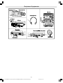
Peripheral Equipment Connections
There is a wide range of audio and video equipment that can
be connected to your TV.
Connection diagrams at the end of this section show you where
the different equipment should be connected at the back side of
the TV.
Via the Euroconnector
Your TV set has 2 Euroconnector sockets. If you want to
connect peripherals (e.g. video, decoder, etc.) which have
Euroconnectors, to your TV, use EXT.1 or EXT.2 input.
If an external device is connected via Euroconnector sockets,
TV is switched to AV mode automatically. In this case if both
sockets are connected, SCART has the precedence.
T-V LINK compatible VCR
Be sure to connect the T-V LINK compatible VCR to the EXT.2
terminal. If not, the T-V LINK function will not work properly.
When connecting a T-V LINK compatible VCR to the EXT.2
terminal, be sure to connect the decoder to the VCR. If not,
the T-V LINK function may not work properly. And then set
the Decoder(EXT2) (see page 9) function for the channel to
ON to unscramble a scrambled channel.
RGB mode
If an equipment can output the RGB signals, connect it to the
EXT.1 terminal.
EXT2S Mode
If the equipment connected to your TV set supports S-Video
(Y/C) output from Euroconnector, you can have a better picture quality by selecting EXT2S mode and connecting your
equipment to the EXT.2 (EXT2S) terminal of TV. See your
equipments booklet to check if your equipment has such feature.
Via the RCA jacks
If you have an equipment (such as a Camcorder) which has
the RCA jacks, connect it to the EXT-3 terminal with the video
and audio cables.
Via the ANT (aerial) socket
number 0. You can watch images from that equipment to
select the program number which you stored the test signal.
Decoder
Cable TV offers you a wide choice of programmes. Some of
them are free, others are to be paid for by the viewer. This
means that you will need to subscribe to the broadcasting
organisation whose programmes you wish to receive. This
organisation will supply you a corresponding decoder unit to
allow the programmes to be unscrambled.
For further information ask your dealer. See also the booklet
supplied with your decoder.
Connect a decoder with an aerial socket to the TV
Connect the aerial cable.
Connect a decoder without an aerial socket to the
TV
Connect the decoder to your TV with a eurocable (RCA Jack
Cable) to EXTERNAL (RCA Jack). When your decoder has a
Euroconnector / RCA Jack you can obtain better picture
quality if you connect a eurocable (RCA Jack Cable) to
EXTERNAL (RCA Jack).
TV and Video Recorder (VCR)
Connect the Video Recorder to the ANT (antenna input) socket
of the TV with the aerial cable.
Connect the Video Recorder to the EXT.1 or EXT.2 terminal
with the SCART cable.
NTSC Playback
Connect a NTSC video recorder to a terminal. Then press AV
button to select the corresponding AV mode.
NTSC 3.58/4.43 system is detected automatically in AV mode.
Camera and Camcorder
To connect to the EXT-3 terminal
Connect your camera or camcorder to the right side of your
TV.
Connect your equipment to the TV via VIDEO (yellow), AUDIO R (red) and AUDIO L (white) inputs. You should connect
the jacks to the input in the same colour.
Connect the decoder to the video recorder
Some video recorders have a special euroconnector for decoder.
Connect a eurocable to the euroconnector of your decoder
and to the special euroconnector of your video recorder. See
also the handbook of your video recorder.
To connect your video recorder to the TV, see TV and Video
Recorder section.
If you want to connect more equipment to your TV, consult
your dealer.
Connecting Headphones
Use the stereo headphone socket of your TV, to connect headphones.
If your equipment does not have an Euroconnector or RCA
jacks, connect it to the TV with an aerial cable. For details,
see the manual provided with the equipment.
To store the test signal that comes from the equipment, see
Installation Menu on page 8 and store it to the program
- 12 A01-ENG&AK49-C1512UK-2929-RF-CLED-PLLCH-(AV-29QT4SU)-10041580-50086700.p65
12
18.05.2006, 10:05
Peripheral Equipments
- 13 A01-ENG&AK49-C1512UK-2929-RF-CLED-PLLCH-(AV-29QT4SU)-10041580-50086700.p65
13
18.05.2006, 10:05
Tips
Specifications
Can not turn the TV on?
Check that TV/VCR/DVD switch is set to TV position.
TV may go to stand-by mode when you turn the TV on soon
after you turn the TV off. If you can turn the TV on again, it is
not a problem.
Can not turn the TV off?
Broadcasting System
PAL SECAM B/G D/K K I/I L/L
Channels and Frequencies
Analogue: 46.25 MHz - 862.25 MHz (channel 01-17/21-73)
Cable TV: S1 - S41
Sound System
A2+Nicam Stereo
Check that TV/VCR/DVD switch is set to TV position.
Care of the Screen
Clean the screen with a slightly damp, soft cloth. Do not use
abrasive solvents as they may damage the TV screen coating
layer.
Colours of image on screen are abnormal
Have you selected the correct TV system? Is your TV set or
house aerial located too close to the loudspeakers, non-earthed
audio equipment or neon lights, etc. ?
Mountains or high buildings can cause double pictures or ghost
images. Sometimes you can improve the picture quality by
changing the direction of the aerial.
Is the picture or Teletext unrecognisable? Check if you have
entered the correct frequency.
The picture quality may degrade when two peripherals are
connected to the TV at the same time. In such a case, disconnect one of the peripherals.
No Image on Display Screen
Is the aerial connected properly? Are the plugs connected
tightly to the aerial socket? Is the aerial cable damaged? Are
suitable plugs used to connect the aerial? If you are in doubt,
consult your dealer.
No Image means that your TV is not receiving any transmission. Have you pressed the correct buttons on the remote
control? Try once more.
Sound
You can not hear any sound. Did you perhaps interrupt the
sound, pressing button? Are external speakers connected
to the TV?
Sound is coming from only one of the speakers. Is the balance set to one direction extreme? See Sound menu.
Remote Control
If your TV no longer responds to the remote control, perhaps
the batteries are exhausted. Replace the batteries.
Have you selected the wrong menu? Press MENU button to
return to normal screen.
No solution
If the TV suddenly stops responding, disconnect the power
cord of the TV from the AC outlet. Connect it to the AC outlet
again to turn on the TV. If the TV returns to a normal state, it is
not a failure. If this does not work, switch off, remove the mains
plug and call the service personnel; never attempt to repair it
yourself.
Power Requirements
220-240 V AC, 50 Hz
Power Consumption
130W (Standby < 3W)
Picture Tube Size
Viewable area 72cm .(measured diagonally)
Audio Output
2x10 W RMS (10% THD)
EXT.1 Terminal
Euroconnector (21-pin, SCART)
* Video Input, Audio L/R Inputs and RGB Inputs are available.
* Analogue TV broadcast output (Video and Audio L/R) are
available.
EXT.2 Terminal
Euroconnector (21-pin, SCART)
* Video Input, S-VIDEO (Y/C) Input, Audio L/R Inputs are available.
* Video and Audio L/R outputs are available.
* T-V LINK functions are available.
EXT.3 Terminal
RCA connectors x 3
* Video Input and Audio Inputs are available.
Headphone jack
Stereo mini-jack (3.5 mm in diameter)
Dimensions (WxHxD)
785 mm x 615 mm x 500 mm
Accessories
Remote control unit x 1 (RM-C1512)
AA/R6 dry cell battery x 2
- 14 A01-ENG&AK49-C1512UK-2929-RF-CLED-PLLCH-(AV-29QT4SU)-10041580-50086700.p65
14
18.05.2006, 10:05
PARTS LIST
CAUTION
J The parts identified by the symbol are important for the safety . Whenever replacing these parts, be sure to use specified ones to secure the
safety.
J The parts not indicated in this Parts List and those which are filled with lines --- in the Parts No. columns will not be supplied.
J P.W. BOARD Ass'y will not be supplied, but those which are filled with the Parts No. in the Parts No. columns will be supplied.
ABBREVIATIONS OF RESISTORS, CAPACITORS AND TOLERANCES
RESISTORS
CAPACITORS
CR
Carbon Resistor
C CAP.
Ceramic Capacitor
FR
Fusible Resistor
E CAP.
Electrolytic Capacitor
PR
Plate Resistor
M CAP.
Mylar Capacitor
VR
Variable Resistor
CH CAP.
Chip Capacitor
HV R
High Voltage Resistor
HV CAP.
High Voltage Capacitor
MF R
Metal Film Resistor
MF CAP.
Metalized Film Capacitor
MG R
Metal Glazed Resistor
MM CAP.
Metalized Mylar Capacitor
MP R
Metal Plate Resistor
MP CAP.
Metalized Polystyrol Capacitor
OM R
Metal Oxide Film Resistor
PP CAP.
Polypropylene Capacitor
CMF R
Coating Metal Film Resistor
PS CAP.
Polystyrol Capacitor
UNF R
Non-Flammable Resistor
TF CAP.
Thin Film Capacitor
CH V R
Chip Variable Resistor
MPP CAP.
Metalized Polypropylene Capacitor
CH MG R
Chip Metal Glazed Resistor
TAN. CAP.
Tantalum Capacitor
COMP. R
Composition Resistor
CH C CAP.
Chip Ceramic Capacitor
LPTC R
Linear Positive Temperature Coefficient Resistor
BP E CAP.
Bi-Polar Electrolytic Capacitor
CH AL E CAP.
Chip Aluminum Electrolytic Capacitor
CH AL BP CAP.
Chip Aluminum Bi-Polar Capacitor
CH TAN. E CAP.
Chip Tantalum Electrolytic Capacitor
CH AL BP E CAP.
Chip Tantalum Bi-Polar Electrolytic Capacitor
RESISTORS
F
G
J
K
M
N
R
H
Z
P
±1%
±2%
±5%
±10%
±20%
±30%
+30%
-10%
+50%
-10%
+80%
-20%
+100%
-0%
(No.YA085C)3-1
CONTENTS
USING P.W. BOARD & REMOTE CONTROL UNIT ................................................................................................... 3-2
EXPLODED VIEW PARTS LIST -1 ............................................................................................................................. 3-3
EXPLODED VIEW -1 ................................................................................................................................................... 3-4
EXPLODED VIEW -2 ................................................................................................................................................... 3-5
PRINTED WIRING BOARD PARTS LIST ................................................................................................................... 3-6
MAIN P.W. BOARD ASS'Y (VE-20265029) ....................................................................................................... 3-6
CRT SOCKET P.W. BOARD ASS'Y (VE-20247134) ......................................................................................... 3-9
SIDE CONTROL P.W. BOARD ASS'Y (VE-20166350) ................................................................................... 3-10
AV & HEADPHONE P.W. BOARD ASS'Y (VE-20226778) .............................................................................. 3-10
LED P.W. BOARD ASS'Y (VE-20167316) ....................................................................................................... 3-10
POWER SW P.W. BOARD ASS'Y (VE-20209386) ......................................................................................... 3-10
PACKING ................................................................................................................................................................... 3-11
PACKING PARTS LIST ............................................................................................................................................. 3-11
USING P.W. BOARD & REMOTE CONTROL UNIT
P.W.B ASS'Y name
P.W.B ASS'Y No.
MAIN P.W.B
VE-20265029
CRT SOCKET P.W.B
VE-20247134
SIDE CONTROL P.W.B
VE-20166350
AV & HEADPHONE P.W.B
VE-20226778
LED P.W.B
VE-20167316
POWER SW P.W.B
VE-20209386
REMOTE CONTROL UNIT
VE-30021287
3-2(No.YA085C)
EXPLODED VIEW PARTS LIST -1
Ref.No.
Part No.
Part Name
V01
L01
TR601
1
2
3
4
5
6
7
8
9
10
11
12
13
14
15
16
17
18
51
52
53
54
55
56
57
58
59
60
61
62
63
VE-THO021X101
VE-30042103
VE-30037592
VE-20161157
VE-20166395
VE-20153568
VE-20153721
VE-20161162
VE-35000020
VE-40021572
VE-30024903
VE-30024912
VE-20161160
VE-40026402
VE-40024096
VE-20170313
VE-35011401
VE-35000212
VE-40000082
VE-40024076
VE-30016513
VE-30032688
VE-30038428
VE-30038429
VE-30032691
VE-30019083
VE-30032963
VE-30028075
VE-30028074
VE-30013905
VE-30012634
VE-30042967
VE-30016864
VE-30016865
PICTURE TUBE
DEG. COIL & EARTH
FB TRANSF.
FRONT CABINET
LENS
LENS (LED)
LENS (IR SENSOR)
ON/OFF BUTTON
SPRING (ON/OFF SWITCH)
JVC LOGO
SPEAKER
TWEETER
FUNCTION BUTTON
CHASSIS FRAME
BACK DOOR
REAR COVER
SCREW
SCREW
RUBBER FOOT
CABLE HOLDER
POWER CORD
E-HARNESS ASSY
E-HARNESS ASSY
E-HARNESS ASSY
E-HARNESS ASSY
E-HARNESS ASSY
E-HARNESS ASSY
E-HARNESS ASSY
E-HARNESS ASSY
E-HARNESS ASSY
E-HARNESS ASSY
E-HARNESS ASSY
E-HARNESS ASSY
E-HARNESS ASSY
VE-20265029
VE-20247134
VE-20166350
VE-20226778
VE-20209386
VE-20167316
MAIN PWB
CRT SOCKET PWB
SIDE CONTROL PWB
AV & HEADPHONE PWB
POWER SW PWB
LED PWB
101
102
103
104
105
106
Description
Local
POWER
8ohm 15W 57x126mm(x2)
8ohm 8W 51mm
(M4x18.5) For REAR COVER(x8)
(M2.9x13) For BACK DOOR(x4)
(x4)
2.2m
MAIN PL102 - SIDE CONTROL PWB
MAIN PL101 - LED PWB
MAIN PL103 - LED PWB
MAIN PL800 - POWER SW PWB
MAIN PL603 - DEF YOKE
MAIN PL602 - DEF YOKE
MAIN PL605 - CRT PL902
MAIN PL105 - CRT PL901
AV&HP PL107 - SPEAKER (RIGHT)
AV&HP PL106 - SPEAKER (LEFT)
MAIN PL115+PL116 - AV&HP PL104+PL105
MAIN PL404 - AV&HP PWB
MAIN PL401 - AV&HP PWB
(No.YA085C)3-3
EXPLODED VIEW -1
14
15
13
L01
102
103
104
10
1
V01
12
105
9
106
7
101
5
8
TR601
6
4
9
3
16
17
11
3-4(No.YA085C)
18
2
EXPLODED VIEW -2
LED PWB
(SOLDER SIDE)
POWER SW PWB
FRONT
TOP
SIDE CONTROL
PWB
54
53
52
MAIN PWB
TOP
FRONT
MENU
PL800
P/Ch
51
PL101
PL404
AV &
HEADPHONE
62 63
PWB
PL401
55
PL103
PL102
PL105
DEF.
YOKE
TOP
PL602
PL106
56
PL107
PL104
PL603
PL105
PL115
61
FRONT
PL605
59
SPEAKER
R
PL116
SPEAKER
L
60
57
PL902
58
TOP
PL901
CRT SOCKET PWB
(SOLDER SIDE)
(No.YA085C)3-5
PRINTED WIRING BOARD PARTS LIST
MAIN P.W. BOARD ASS'Y (VE-20265029)
Ref No.
Part No.
Part Name
IC100
IC101
IC400
IC403
IC600
IC601
IC800
IC801
IC802
IC803
IC804
IC805
IC806
VE-30029324
VE-20265033
VE-30027557
VE-30038486
VE-30001665
VE-30013612
VE-30001668
VE-30001668
VE-30001384
VE-30001270
VE-30031947
VE-30015087
VE-30031524
IC
IC
IC
IC
IC
IC
IC
IC
TRANSISTOR
PTC
IC
IC
IC
Q100
Q101
Q102
Q103
Q104
Q106
Q107
Q108
Q109
Q110
Q113
Q114
Q115
Q116
Q117
Q118
Q119
Q121
Q122
Q401
Q402
Q403
Q600
Q601
Q602
Q603
Q604
Q605
Q607
Q608
Q801
Q802
Q805
Q806
Q807
Q808
Q809
Q810
Q811
Q812
Q813
VE-30029775
VE-30001457
VE-30029775
VE-30029775
VE-30001458
VE-30001452
VE-30029322
VE-30001457
VE-30024724
VE-30001457
VE-30001452
VE-30001457
VE-30001458
VE-30001457
VE-30001458
VE-30001457
VE-30001457
VE-30001458
VE-30001457
VE-30001458
VE-30001457
VE-30001458
VE-30001441
VE-30031823
VE-30007799
VE-30001457
VE-30001458
VE-30001426
VE-30001458
VE-30001458
VE-30001457
VE-30001386
VE-30001454
VE-30001426
VE-30001457
VE-30001457
VE-30001457
VE-30001454
VE-30001454
VE-30001457
VE-30001458
TRANSISTOR
TRANSISTOR
TRANSISTOR
TRANSISTOR
TRANSISTOR
TRANSISTOR
TRANSISTOR
TRANSISTOR
TRANSISTOR
TRANSISTOR
TRANSISTOR
TRANSISTOR
TRANSISTOR
TRANSISTOR
TRANSISTOR
TRANSISTOR
TRANSISTOR
TRANSISTOR
TRANSISTOR
TRANSISTOR
TRANSISTOR
TRANSISTOR
TRANSISTOR
TRANSISTOR
TRANSISTOR
TRANSISTOR
TRANSISTOR
TRANSISTOR
TRANSISTOR
TRANSISTOR
TRANSISTOR
TRANSISTOR
TRANSISTOR
TRANSISTOR
TRANSISTOR
TRANSISTOR
TRANSISTOR
TRANSISTOR
TRANSISTOR
TRANSISTOR
TRANSISTOR
D100
D101
D102
D103
D104
D105
D108
D111
D112
D113
D114
D115
D116
D117
D118
D119
D120
D121
D155
D403
D600
D601
D602
D603
D604
D605
D606
D607
D608
VE-30038493
VE-30001285
VE-30001285
VE-30038493
VE-30012411
VE-30001285
VE-30038472
VE-30038472
VE-30038472
VE-30036987
VE-30036988
VE-30036988
VE-30036987
VE-30036987
VE-30036988
VE-30036988
VE-30036988
VE-30012669
VE-30038497
VE-30001285
VE-30038475
VE-30001285
VE-30001285
VE-30001285
VE-30001320
VE-30007681
VE-30001318
VE-30038476
VE-30038492
DIODE
DIODE
DIODE
DIODE
DIODE
DIODE
Z DIODE
Z DIODE
Z DIODE
DIODE
DIODE
DIODE
DIODE
DIODE
DIODE
DIODE
DIODE
RESISTOR
DIODE
DIODE
DIODE
DIODE
DIODE
DIODE
DIODE
DIODE
DIODE
Z DIODE
Z DIODE
3-6(No.YA085C)
Ref No.
Description Local
(SERVICE)
1/16W 22K J
Part No.
Part Name
D609
D610
D611
D612
D613
D614
D616
D618
D620
D622
D800
D801
D802
D805
D806
D808
D809
D810
D811
D813
D814
D815
D816
D817
D818
D819
D820
D822
D823
D827
VE-30001318
VE-30001288
VE-30001318
VE-30001318
VE-30001318
VE-30038472
VE-30001285
VE-30038504
VE-30038472
VE-30001285
VE-20108354
VE-30001329
VE-30001318
VE-30001318
VE-30001318
VE-30001288
VE-30001288
VE-30038472
VE-30001318
VE-30001285
VE-30001343
VE-30001285
VE-30001323
VE-30034072
VE-30009366
VE-30001288
VE-30009366
VE-30001318
VE-30001329
VE-30038478
DIODE
DIODE
DIODE
DIODE
DIODE
Z DIODE
DIODE
DIODE
Z DIODE
DIODE
DIODE
DIODE
DIODE
DIODE
DIODE
DIODE
DIODE
Z DIODE
DIODE
DIODE
DIODE
DIODE
DIODE
DIODE
DIODE
DIODE
DIODE
DIODE
DIODE
DIODE
C100
C101
C107
C108
C114
C115
C116
C117
C119
C120
C121
C122
C126
C127
C128
C129
C130
C131
C132
C133
C134
C135
C136
C137
C138
C139
C140
C141
C142
C143
C144
C145
C146
C147
C148
C151
C152
C153
C154
C155
C156
C157
C158
C161
C162
C163
C164
C165
C166
C167
C168
C169
C170
C171
C172
C173
VE-30016654
VE-30000371
VE-30016654
VE-30016654
VE-30000345
VE-30012586
VE-30016126
VE-30016654
VE-30000371
VE-30016654
VE-30016126
VE-30016126
VE-30016126
VE-30000345
VE-30000345
VE-30016654
VE-30016654
VE-30016126
VE-30012610
VE-30016126
VE-30016126
VE-30000352
VE-30016126
VE-30000352
VE-30000352
VE-30016654
VE-30016126
VE-30016126
VE-30016126
VE-30012609
VE-30016654
VE-30000352
VE-30012610
VE-30000345
VE-30016654
VE-30012617
VE-30012585
VE-30000352
VE-30012577
VE-30000345
VE-30016654
VE-30016126
VE-30000352
VE-30012610
VE-30000396
VE-30000362
VE-30012586
VE-30016126
VE-30000345
VE-30012581
VE-30012581
VE-30000083
VE-30016654
VE-30016654
VE-30016654
VE-30016654
CAPACITOR
E CAPACITOR
CAPACITOR
CAPACITOR
E CAPACITOR
CAPACITOR
CAPACITOR
CAPACITOR
E CAPACITOR
CAPACITOR
CAPACITOR
CAPACITOR
CAPACITOR
E CAPACITOR
E CAPACITOR
CAPACITOR
CAPACITOR
CAPACITOR
CAPACITOR
CAPACITOR
CAPACITOR
E CAPACITOR
CAPACITOR
E CAPACITOR
E CAPACITOR
CAPACITOR
CAPACITOR
CAPACITOR
CAPACITOR
CAPACITOR
CAPACITOR
E CAPACITOR
CAPACITOR
E CAPACITOR
CAPACITOR
CAPACITOR
CAPACITOR
E CAPACITOR
CAPACITOR
E CAPACITOR
CAPACITOR
CAPACITOR
E CAPACITOR
CAPACITOR
E CAPACITOR
E CAPACITOR
CAPACITOR
CAPACITOR
E CAPACITOR
CAPACITOR
CAPACITOR
CAPACITOR
CAPACITOR
CAPACITOR
CAPACITOR
CAPACITOR
Description Local
100nF 16V K
22uF 50V M
100nF 16V K
100nF 16V K
10uF 50V M
22nF 50V K
220nF 16V K
100nF 16V K
22uF 50V M
100nF 16V K
220nF 16V K
220nF 16V K
220nF 16V K
10uF 50V M
10uF 50V M
100nF 16V K
100nF 16V K
220nF 16V K
10nF 50V J
220nF 16V K
220nF 16V K
100uF 16V M
220nF 16V K
100uF 16V M
100uF 16V M
100nF 16V K
220nF 16V K
220nF 16V K
220nF 16V K
68nF 50V K
100nF 16V K
100uF 16V M
10nF 50V J
10uF 50V M
100nF 16V K
6.8nF 50V M
2.2nF 50V K
100uF 16V M
560pF 50V J
10uF 50V M
100nF 16V K
220nF 16V K
100uF 16V M
10nF 50V J
47uF 16V M
1uF 50V M
22nF 50V K
220nF 16V K
10uF 50V M
1nF 50V K
1nF 50V K
150nF 63V J
100nF 16V K
100nF 16V K
100nF 16V K
100nF 16V K
Ref No.
C174
C175
C176
C178
C179
C180
C181
C182
C183
C184
C185
C186
C187
C189
C190
C191
C192
C193
C194
C195
C196
C197
C199
C200
C201
C203
C204
C205
C206
C207
C208
C210
C211
C212
C213
C222
C223
C236
C237
C238
C239
C240
C241
C242
C243
C244
C245
C250
C251
C252
C253
C254
C256
C257
C259
C260
C272
C273
C274
C278
C279
C280
C281
C283
C400
C401
C402
C403
C404
C405
C406
C407
C408
C409
C410
C411
C412
C413
C414
C415
C416
C417
C418
C419
C420
C427
C428
C429
C430
C431
Part No.
Part Name
VE-30016654
VE-30016654
VE-30016654
VE-30012610
VE-30016126
VE-30012610
VE-30012603
VE-30016654
VE-30024768
VE-30024768
VE-30016654
VE-30016654
VE-30000345
VE-30012587
VE-30024768
VE-30016654
VE-30000413
VE-30016654
VE-30024768
VE-30000384
VE-30000384
VE-30000384
VE-30000384
VE-30016654
VE-30016654
VE-30012610
VE-30000345
VE-30000345
VE-30024768
VE-30016654
VE-30024768
VE-30000384
VE-30000384
VE-30016654
VE-30000352
VE-30012581
VE-30012581
VE-30012581
VE-30012581
VE-30012589
VE-30012603
VE-30012566
VE-30012566
VE-30012566
VE-30012566
VE-30012607
VE-30012573
VE-30012589
VE-30012589
VE-30012589
VE-30012581
VE-30012581
VE-30012566
VE-30012603
VE-30012607
VE-30012566
VE-30012607
VE-30012581
VE-30012581
VE-30000396
VE-30000396
VE-30000396
VE-30000352
VE-30000400
VE-30012580
VE-30012577
VE-30012581
VE-30000392
VE-30012581
VE-30012577
VE-30012590
VE-30000371
VE-30012577
VE-30012577
VE-30000371
VE-30012590
VE-30012609
VE-30007082
VE-30007179
VE-30000409
VE-30000409
VE-30012581
VE-30012581
VE-30000392
VE-30012580
VE-30000296
VE-30012603
VE-30007082
VE-30012603
VE-30012609
CAPACITOR
CAPACITOR
CAPACITOR
CAPACITOR
CAPACITOR
CAPACITOR
CAPACITOR
CAPACITOR
CAPACITOR
CAPACITOR
CAPACITOR
CAPACITOR
E CAPACITOR
CAPACITOR
CAPACITOR
CAPACITOR
E CAPACITOR
CAPACITOR
CAPACITOR
E CAPACITOR
E CAPACITOR
E CAPACITOR
E CAPACITOR
CAPACITOR
CAPACITOR
CAPACITOR
E CAPACITOR
E CAPACITOR
CAPACITOR
CAPACITOR
CAPACITOR
E CAPACITOR
E CAPACITOR
CAPACITOR
E CAPACITOR
CAPACITOR
CAPACITOR
CAPACITOR
CAPACITOR
CAPACITOR
CAPACITOR
CAPACITOR
CAPACITOR
CAPACITOR
CAPACITOR
CAPACITOR
CAPACITOR
CAPACITOR
CAPACITOR
CAPACITOR
CAPACITOR
CAPACITOR
CAPACITOR
CAPACITOR
CAPACITOR
CAPACITOR
CAPACITOR
CAPACITOR
CAPACITOR
E CAPACITOR
E CAPACITOR
E CAPACITOR
E CAPACITOR
E CAPACITOR
CAPACITOR
CAPACITOR
CAPACITOR
E CAPACITOR
CAPACITOR
CAPACITOR
CAPACITOR
E CAPACITOR
CAPACITOR
CAPACITOR
E CAPACITOR
CAPACITOR
CAPACITOR
CAPACITOR
E CAPACITOR
E CAPACITOR
E CAPACITOR
CAPACITOR
CAPACITOR
E CAPACITOR
CAPACITOR
C CAPACITOR
CAPACITOR
CAPACITOR
CAPACITOR
CAPACITOR
Description Local
100nF 16V K
100nF 16V K
100nF 16V K
10nF 50V J
220nF 16V K
10nF 50V J
100nF 25V K
100nF 16V K
470nF 16V Z
470nF 16V Z
100nF 16V K
100nF 16V K
10uF 50V M
3.3nF 50V K
470nF 16V Z
100nF 16V K
4.7uF 50V M
100nF 16V K
470nF 16V Z
2.2uF 50V M
2.2uF 50V M
2.2uF 50V M
2.2uF 50V M
100nF 16V K
100nF 16V K
10nF 50V J
10uF 50V M
10uF 50V M
470nF 16V Z
100nF 16V K
470nF 16V Z
2.2uF 50V M
2.2uF 50V M
100nF 16V K
100uF 16V M
1nF 50V K
1nF 50V K
1nF 50V K
1nF 50V K
4.7nF 50V K
100nF 25V K
22pF 50V J
22pF 50V J
22pF 50V J
22pF 50V J
150pF 50V J
47pF 50V J
4.7nF 50V K
4.7nF 50V K
4.7nF 50V K
1nF 50V K
1nF 50V K
22pF 50V J
100nF 25V K
150pF 50V J
22pF 50V J
150pF 50V J
1nF 50V K
1nF 50V K
47uF 16V M
47uF 16V M
47uF 16V M
100uF 16V M
47uF 50V M
820pF 50V J
560pF 50V J
1nF 50V K
0.33uF 50V M
1nF 50V K
560pF 50V J
47nF 50V K
22uF 50V M
560pF 50V J
560pF 50V J
22uF 50V M
47nF 50V K
68nF 50V K
680nF 63V J
33uF 100V M
470uF 25V
470uF 25V
1nF 50V K
1nF 50V K
0.33uF 50V M
820pF 50V J
100nF 100V Z
100nF 25V K
680nF 63V J
100nF 25V K
68nF 50V K
Ref No.
Part No.
Part Name
C432
C433
C439
C440
C441
C449
C450
C600
C601
C602
C603
C604
C605
C606
C607
C608
C609
C610
C611
C612
C613
C615
C616
C617
C618
C619
C620
C621
C622
C623
C624
C625
C626
C627
C629
C630
C631
C633
C634
C636
C637
C638
C639
C640
C641
C642
C800
C801
C802
C807
C808
C810
C811
C813
C814
C815
C818
C819
C820
C822
C825
C826
C827
C828
C829
C830
C831
C832
C833
C834
C836
C839
C840
C841
C842
C843
C844
C845
C847
C848
C849
C850
C851
C852
C853
C854
C855
C856
C857
C859
VE-30000296
VE-30000109
VE-30012567
VE-30000109
VE-30000296
VE-30000352
VE-30016654
VE-30000400
VE-30000353
VE-30016654
VE-30000400
VE-30000407
VE-30000074
VE-30000090
VE-30023449
VE-30023480
VE-30000107
VE-30000346
VE-30000119
VE-30000296
VE-30000172
VE-30000124
VE-30000374
VE-30000433
VE-30012590
VE-30000296
VE-30000391
VE-30012590
VE-30000296
VE-30012590
VE-30000444
VE-30000409
VE-30000400
VE-30000350
VE-30000406
VE-30000346
VE-30012590
VE-30000296
VE-30000283
VE-30000092
VE-30000100
VE-30012567
VE-30000345
VE-30012590
VE-30019702
VE-30016654
VE-30000433
VE-30000084
VE-30000094
VE-30000161
VE-30000393
VE-30000421
VE-30000319
VE-30000387
VE-30000161
VE-30007308
VE-30009208
VE-30000440
VE-30000440
VE-30000330
VE-30012567
VE-30007708
VE-30000406
VE-30000436
VE-30006753
VE-30006753
VE-30012603
VE-30012603
VE-30012603
VE-30016654
VE-30016654
VE-30016654
VE-30000400
VE-30000383
VE-30000383
VE-30000360
VE-30000383
VE-30000382
VE-30000367
VE-30016654
VE-30000283
VE-30012581
VE-30016654
VE-30016654
VE-30016654
VE-30000362
VE-30031826
VE-30016654
VE-30031825
VE-30000352
C CAPACITOR
CAPACITOR
CAPACITOR
CAPACITOR
C CAPACITOR
E CAPACITOR
CAPACITOR
E CAPACITOR
E CAPACITOR
CAPACITOR
E CAPACITOR
E CAPACITOR
CAPACITOR
CAPACITOR
CAPACITOR
CAPACITOR
CAPACITOR
E CAPACITOR
CAPACITOR
C CAPACITOR
CAPACITOR
CAPACITOR
E CAPACITOR
C CAPACITOR
CAPACITOR
C CAPACITOR
E CAPACITOR
CAPACITOR
C CAPACITOR
CAPACITOR
C CAPACITOR
E CAPACITOR
E CAPACITOR
E CAPACITOR
E CAPACITOR
E CAPACITOR
CAPACITOR
C CAPACITOR
C CAPACITOR
CAPACITOR
CAPACITOR
CAPACITOR
E CAPACITOR
CAPACITOR
CAPACITOR
CAPACITOR
C CAPACITOR
CAPACITOR
CAPACITOR
CAPACITOR
E CAPACITOR
E CAPACITOR
C CAPACITOR
E CAPACITOR
CAPACITOR
C CAPACITOR
C CAPACITOR
C CAPACITOR
C CAPACITOR
C CAPACITOR
CAPACITOR
C CAPACITOR
E CAPACITOR
C CAPACITOR
C CAPACITOR
C CAPACITOR
CAPACITOR
CAPACITOR
CAPACITOR
CAPACITOR
CAPACITOR
CAPACITOR
E CAPACITOR
E CAPACITOR
E CAPACITOR
E CAPACITOR
E CAPACITOR
E CAPACITOR
E CAPACITOR
CAPACITOR
C CAPACITOR
CAPACITOR
CAPACITOR
CAPACITOR
CAPACITOR
E CAPACITOR
E CAPACITOR
CAPACITOR
E CAPACITOR
E CAPACITOR
Description Local
100nF 100V Z
470nF 63V J
220pF 50V J
470nF 63V J
100nF 100V Z
100uF 16V M
100nF 16V K
47uF 50V M
100uF 25V M
100nF 16V K
47uF 50V M
470uF 16V M
100nF 63V J
22nF 100V J
4.7nF 2000VDC J
10nF 2000VDC
47nF 250V J
10uF 100V M
12nF 630VDC J
100nF 100V Z
680nF 250V J
620nF 250V
22UF250V M
1nF 1KV M
47nF 50V K
100nF 100V Z
330uF 63V M
47nF 50V K
100nF 100V Z
47nF 50V K
470pF 1KV K
470uF 25V
47uF 50V M
10uF 250V M
47uF 250V M
10uF 100V M
47nF 50V K
100nF 100V Z
1nF 50V K
220nF 63V J
330nF 63V J
220pF 50V J
10uF 50V M
47nF 50V K
1.2uF 250V J
100nF 16V K
1nF 1KV M
150nF 275V M
220nF 275V M
47nF 630VDC J
3.3uF 50V M
220uF 400V M
2.7nF 500V K
33uF 50V M
47nF 630VDC J
220pF 1KV K
470pF 1KV K
2.2nF 4KV M
2.2nF 4KV M
4.7nF 50V K
220pF 50V J
1nF 1KV K
47uF 250V M
10nF 1KV Z
220pF 1KV K
220pF 1KV K
100nF 25V K
100nF 25V K
100nF 25V K
100nF 16V K
100nF 16V K
100nF 16V K
47uF 50V M
2200uF 25V M
2200uF 25V M
1000uF 25V M
2200uF 25V M
2200uF 16V M
1uF 250V M
100nF 16V K
1nF 50V K
1nF 50V K
100nF 16V K
100nF 16V K
100nF 16V K
1uF 50V M
4700uF 6.3V M
100nF 16V K
2200uF 6.3V M
100uF 16V M
(No.YA085C)3-7
Ref No.
Part No.
Part Name
C862
VE-30012642
RESISTOR
1/16W 120K J
R100
R101
R102
R103
R104
R105
R106
R107
R108
R111
R112
R113
R114
R115
R116
R117
R118
R119
R126
R127
R128
R129
R132
R133
R137
R138
R139
R141
R142
R143
R144
R145
R147
R148
R149
R150
R155
R158
R159
R160
R167
R168
R170
R171
R172
R173
R174
R175
R176
R178
R179
R180
R181
R182
R185
R187
R192
R193
R195
R196
R197
R198
R199
R200
R201
R202
R203
R204
R205
R206
R207
R208
R209
R212
R214
R215
R216
R217
R218
R219
R220
R222
R223
R224
R230
R231
R233
R234
VE-30000583
VE-30000626
VE-30012677
VE-30000459
VE-30012692
VE-30012510
VE-30012692
VE-30012692
VE-30012510
VE-30000459
VE-30000459
VE-30012677
VE-30012641
VE-30012668
VE-30012657
VE-30012655
VE-30012677
VE-30012677
VE-30012669
VE-30012648
VE-30012692
VE-30012695
VE-30012657
VE-30012659
VE-30012510
VE-30000459
VE-30000459
VE-30000459
VE-30000459
VE-30012650
VE-30000594
VE-30012657
VE-30012641
VE-30012641
VE-30000459
VE-30012510
VE-30012650
VE-30012510
VE-30000459
VE-30012650
VE-30012669
VE-30000718
VE-30000628
VE-30000459
VE-30012510
VE-30012510
VE-30012510
VE-30012641
VE-30012668
VE-30000599
VE-30012510
VE-30012510
VE-30012650
VE-30000459
VE-30012510
VE-30006712
VE-30012510
VE-30012510
VE-30012695
VE-30012657
VE-30012657
VE-30000495
VE-30000975
VE-30000770
VE-30000477
VE-30012642
VE-30012696
VE-30012504
VE-30012510
VE-30012688
VE-30000459
VE-30000459
VE-30012644
VE-30012510
VE-30012644
VE-30012641
VE-30012641
VE-30012641
VE-30012708
VE-30012641
VE-30012641
VE-30012510
VE-30012510
VE-30012510
VE-30012641
VE-30012510
VE-30000459
VE-30012641
RESISTOR
RESISTOR
RESISTOR
RESISTOR
RESISTOR
RESISTOR
RESISTOR
RESISTOR
RESISTOR
RESISTOR
RESISTOR
RESISTOR
RESISTOR
RESISTOR
RESISTOR
RESISTOR
RESISTOR
RESISTOR
RESISTOR
RESISTOR
RESISTOR
RESISTOR
RESISTOR
RESISTOR
RESISTOR
RESISTOR
RESISTOR
RESISTOR
RESISTOR
RESISTOR
RESISTOR
RESISTOR
RESISTOR
RESISTOR
RESISTOR
RESISTOR
RESISTOR
RESISTOR
RESISTOR
RESISTOR
RESISTOR
RESISTOR
RESISTOR
RESISTOR
RESISTOR
RESISTOR
RESISTOR
RESISTOR
RESISTOR
RESISTOR
RESISTOR
RESISTOR
RESISTOR
RESISTOR
RESISTOR
FERRITE BEAD
RESISTOR
RESISTOR
RESISTOR
RESISTOR
RESISTOR
RESISTOR
RESISTOR
RESISTOR
RESISTOR
RESISTOR
RESISTOR
RESISTOR
RESISTOR
RESISTOR
RESISTOR
RESISTOR
RESISTOR
RESISTOR
RESISTOR
RESISTOR
RESISTOR
RESISTOR
RESISTOR
RESISTOR
RESISTOR
RESISTOR
RESISTOR
RESISTOR
RESISTOR
RESISTOR
RESISTOR
RESISTOR
1/4W 220R
1/10W 270R J
1/16W 3.3K J
1/4W 100R J
1/16W 4.7K J
1/16W 100R J
1/16W 4.7K J
1/16W 4.7K J
1/16W 100R J
1/4W 100R J
1/4W 100R J
1/16W 3.3K J
1/16W 10K J
1/16W 220R J
1/16W 1K J
1/16W 180R J
1/16W 3.3K J
1/16W 3.3K J
1/16W 22K J
1/16W 150K J
1/16W 4.7K J
1/16W 470R J
1/16W 1K J
1/16W 2.2K J
1/16W 100R J
1/4W 100R J
1/4W 100R J
1/4W 100R J
1/4W 100R J
1/16W 15K J
1/4W 22K J
1/16W 1K J
1/16W 10K J
1/16W 10K J
1/4W 100R J
1/16W 100R J
1/16W 15K J
1/16W 100R J
1/4W 100R J
1/16W 15K J
1/16W 22K J
1/4W 4.7K J
1/4W 2.7K J
1/4W 100R J
1/16W 100R J
1/16W 100R J
1/16W 100R J
1/16W 10K J
1/16W 220R J
1/4W 220K J
1/16W 100R J
1/16W 100R J
1/16W 15K J
1/4W 100R J
1/16W 100R J
3-8(No.YA085C)
Description Local
1/16W 100R J
1/16W 100R J
1/16W 470R J
1/16W 1K J
1/16W 1K J
1/4W 1.2K J
1/4W 39K J
1/4W 680R J
1/4W 100K J
1/16W 120K J
1/16W 47K J
1/16W 1.2K J
1/16W 100R J
1/16W 390R J
1/4W 100R J
1/4W 100R J
1/16W 12K J
1/16W 100R J
1/16W 12K J
1/16W 10K J
1/16W 10K J
1/16W 10K J
1/16W 68K J
1/16W 10K J
1/16W 10K J
1/16W 100R J
1/16W 100R J
1/16W 100R J
1/16W 10K J
1/16W 100R J
1/4W 100R J
1/16W 10K J
Ref No.
Part No.
Part Name
R235
R236
R237
R238
R240
R241
R242
R244
R245
R246
R247
R248
R249
R250
R251
R252
R265
R266
R267
R268
R269
R270
R271
R272
R273
R274
R275
R276
R277
R278
R279
R280
R281
R282
R283
R298
R299
R300
R302
R304
R305
R307
R308
R316
R318
R327
R328
R400
R401
R402
R403
R406
R407
R408
R409
R410
R411
R412
R413
R414
R415
R416
R417
R418
R425
R426
R428
R429
R432
R433
R434
R435
R438
R439
R440
R441
R600
R601
R602
R603
R604
R605
R606
R608
R610
R611
R612
R613
R614
R615
VE-30012641
VE-30000471
VE-30000471
VE-30012641
VE-30012641
VE-30012641
VE-30012510
VE-30012702
VE-30000459
VE-30012510
VE-30012982
VE-30012657
VE-30012509
VE-30014078
VE-30012713
VE-30012668
VE-30012684
VE-30012684
VE-30012713
VE-30012677
VE-30012510
VE-30012510
VE-30012510
VE-30000471
VE-30012713
VE-30012713
VE-30014078
VE-30012657
VE-30012510
VE-30012510
VE-30012713
VE-30012713
VE-30000466
VE-30012509
VE-30012713
VE-30012684
VE-30012684
VE-30012641
VE-30012713
VE-30012510
VE-30012677
VE-30012713
VE-30012510
VE-30012510
VE-30012713
VE-30012510
VE-30012510
VE-30012510
VE-30012657
VE-30012709
VE-30000689
VE-30000572
VE-30000572
VE-30012641
VE-30012679
VE-30000466
VE-30001207
VE-30012641
VE-30012689
VE-30012679
VE-30012643
VE-30000689
VE-30012657
VE-30012709
VE-30000452
VE-30012689
VE-30012650
VE-30000580
VE-30012641
VE-30012698
VE-30012510
VE-30000580
VE-30012641
VE-30012641
VE-30012659
VE-30012510
VE-30000452
VE-30000770
VE-30000477
VE-30012656
VE-30012654
VE-30000452
VE-30012659
VE-30000458
VE-30000459
VE-30012708
VE-30007200
VE-30001244
VE-30012641
VE-30012657
RESISTOR
RESISTOR
RESISTOR
RESISTOR
RESISTOR
RESISTOR
RESISTOR
RESISTOR
RESISTOR
RESISTOR
RESISTOR
RESISTOR
RESISTOR
RESISTOR
RESISTOR
RESISTOR
RESISTOR
RESISTOR
RESISTOR
RESISTOR
RESISTOR
RESISTOR
RESISTOR
RESISTOR
RESISTOR
RESISTOR
RESISTOR
RESISTOR
RESISTOR
RESISTOR
RESISTOR
RESISTOR
RESISTOR
RESISTOR
RESISTOR
RESISTOR
RESISTOR
RESISTOR
RESISTOR
RESISTOR
RESISTOR
RESISTOR
RESISTOR
RESISTOR
RESISTOR
RESISTOR
RESISTOR
RESISTOR
RESISTOR
RESISTOR
RESISTOR
RESISTOR
RESISTOR
RESISTOR
RESISTOR
RESISTOR
FUSE RESISTOR
RESISTOR
RESISTOR
RESISTOR
RESISTOR
RESISTOR
RESISTOR
RESISTOR
RESISTOR
RESISTOR
RESISTOR
RESISTOR
RESISTOR
RESISTOR
RESISTOR
RESISTOR
RESISTOR
RESISTOR
RESISTOR
RESISTOR
RESISTOR
RESISTOR
RESISTOR
RESISTOR
RESISTOR
RESISTOR
RESISTOR
RESISTOR
RESISTOR
RESISTOR
RESISTOR
FUSE RESISTOR
RESISTOR
RESISTOR
Description Local
1/16W 10K J
1/4W 10K J
1/4W 10K J
1/16W 10K J
1/16W 10K J
1/16W 10K J
1/16W 100R J
1/16W 560R J
1/4W 100R J
1/16W 100R J
1/16W 10R J
1/16W 1K J
1/16W 100K J
1/16W 22R J
1/16W 75R J
1/16W 220R J
1/16W 330R J
1/16W 330R J
1/16W 75R J
1/16W 3.3K J
1/16W 100R J
1/16W 100R J
1/16W 100R J
1/4W 10K J
1/16W 75R J
1/16W 75R J
1/16W 22R J
1/16W 1K J
1/16W 100R J
1/16W 100R J
1/16W 75R J
1/16W 75R J
1/4W 1K J
1/16W 100K J
1/16W 75R J
1/16W 330R J
1/16W 330R J
1/16W 10K J
1/16W 75R J
1/16W 100R J
1/16W 3.3K J
1/16W 75R J
1/16W 100R J
1/16W 100R J
1/16W 75R J
1/16W 100R J
1/16W 100R J
1/16W 100R J
1/16W 1K J
1/16W 7.5K J
1/4W 3.9K J
1/4W 2K J
1/4W 2K J
1/16W 10K J
1/16W 3.9K J
1/4W 1K J
1/4W 10R J
1/16W 10K J
1/16W 39K J
1/16W 3.9K J
1/16W 120R J
1/4W 3.9K J
1/16W 1K J
1/16W 7.5K J
1/4W 10R J
1/16W 39K J
1/16W 15K J
1/4W 22R J
1/16W 10K J
1/16W 5.6K J
1/16W 100R J
1/4W 22R J
1/16W 10K J
1/16W 10K J
1/16W 2.2K J
1/16W 100R J
1/4W 10R J
1/4W 680R J
1/4W 100K J
1/16W 18K J
1/16W 180K J
1/4W 10R J
1/16W 2.2K J
1/2W 100R J
1/4W 100R J
1/16W 68K J
1/4W 10K F
1/2W 0.47R J
1/16W 10K J
1/16W 1K J
Ref No.
Part No.
Part Name
R616
R617
R618
R620
R621
R622
R623
R624
R625
R626
R627
R628
R629
R630
R631
R632
R633
R634
R635
R636
R637
R638
R639
R640
R641
R642
R643
R644
R645
R646
R647
R648
R649
R650
R651
R652
R653
R800
R801
R802
R806
R809
R810
R811
R812
R813
R815
R816
R817
R818
R820
R825
R826
R827
R828
R829
R830
R831
R832
R833
R834
R835
R836
R837
R838
R839
R840
R841
R842
R843
R844
R846
R847
R848
R849
R850
R851
R852
R853
R854
R855
R856
R857
R858
R859
R860
R861
R862
R863
R864
VE-30000649
VE-30012510
VE-30018904
VE-30001082
VE-30000459
VE-30014467
VE-30000459
VE-30000590
VE-30000470
VE-30000590
VE-30001244
VE-30012696
VE-30002828
VE-30001245
VE-30001245
VE-30015578
VE-30001089
VE-30000466
VE-30000628
VE-30001122
VE-30012657
VE-30023224
VE-30000977
VE-30012705
VE-30000848
VE-30000837
VE-30001246
VE-30044855
VE-30015227
VE-30012659
VE-30012659
VE-30000469
VE-30012659
VE-30012662
VE-30012692
VE-30000583
VE-30000480
VE-30018085
VE-30000718
VE-30018085
VE-30000594
VE-30012657
VE-30007784
VE-30000683
VE-30000452
VE-30012692
VE-30001174
VE-30001159
VE-30001257
VE-30012702
VE-30014022
VE-30012641
VE-30014128
VE-30012697
VE-30000718
VE-30012697
VE-30012659
VE-30012641
VE-30012641
VE-30012675
VE-30000880
VE-30012692
VE-30012641
VE-30001173
VE-30012641
VE-30000664
VE-30000664
VE-30012641
VE-30012659
VE-30000477
VE-30012641
VE-30012692
VE-30000481
VE-30000660
VE-30012668
VE-30012657
VE-30000477
VE-30012657
VE-30012697
VE-30012506
VE-30028198
VE-30000459
VE-30000526
VE-30012719
VE-30012641
VE-30012641
VE-30012641
VE-30012641
VE-30012641
VE-30000787
RESISTOR
RESISTOR
RESISTOR
RESISTOR
RESISTOR
RESISTOR
RESISTOR
RESISTOR
RESISTOR
RESISTOR
FUSE RESISTOR
RESISTOR
FUSE RESISTOR
FUSE RESISTOR
FUSE RESISTOR
RESISTOR
RESISTOR
RESISTOR
RESISTOR
RESISTOR
RESISTOR
RESISTOR
RESISTOR
RESISTOR
RESISTOR
RESISTOR
FUSE RESISTOR
RESISTOR
RESISTOR
RESISTOR
RESISTOR
RESISTOR
RESISTOR
RESISTOR
RESISTOR
RESISTOR
RESISTOR
CAPACITOR VAR
RESISTOR
CAPACITOR VAR
RESISTOR
RESISTOR
RESISTOR
RESISTOR
RESISTOR
RESISTOR
RESISTOR
RESISTOR
RESISTOR
RESISTOR
RESISTOR
RESISTOR
RESISTOR
RESISTOR
RESISTOR
RESISTOR
RESISTOR
RESISTOR
RESISTOR
RESISTOR
RESISTOR
RESISTOR
RESISTOR
RESISTOR
RESISTOR
RESISTOR
RESISTOR
RESISTOR
RESISTOR
RESISTOR
RESISTOR
RESISTOR
RESISTOR
RESISTOR
RESISTOR
RESISTOR
RESISTOR
RESISTOR
RESISTOR
RESISTOR
RESISTOR
RESISTOR
RESISTOR
RESISTOR
RESISTOR
RESISTOR
RESISTOR
RESISTOR
RESISTOR
RESISTOR
Description Local
1/2W 33R J
1/16W 100R J
5W 4.7K J
1/2W 1K J
1/4W 100R J
1/16W 680K J
1/4W 100R J
1/4W 2.2K J
1/2W 10K J
1/4W 2.2K J
1/2W 0.47R J
1/16W 47K J
1W 0.75R J
1/4W 0.47R J
1/4W 0.47R J
1/16W 2.2R J
2W 1R J
1/4W 1K J
1/4W 2.7K J
1W 220R J
1/16W 1K J
1/16W 12K F
1/4W 39K F
1/16W 6.8K J
1/4W 1K F
1/4W 9.1K J
1W 0.47R J
1/4W 8.2K F
1/10W 1.2K F
1/16W 2.2K J
1/16W 2.2K J
1/10W 1K J
1/16W 2.2K J
1/16W 2.7K J
1/16W 4.7K J
1/4W 220R
1/10W 100K J
510V K
1/4W 4.7K J
510V K
1/4W 22K J
1/16W 1K J
5W 33K J
1/4W 390R J
1/4W 10R J
1/16W 4.7K J
2W 0.47R J
1W 0.33R J
1/2W 4.7M J
1/16W 560R J
1/16W 47R J
1/16W 10K J
1/16W 33R J
1/16W 5.1K J
1/4W 4.7K J
1/16W 5.1K J
1/16W 2.2K J
1/16W 10K J
1/16W 10K J
1/16W 2K J
1/4W 130K F
1/16W 4.7K J
1/16W 10K J
1W 0.47R J
1/16W 10K J
1/10W 3.3K J
1/10W 3.3K J
1/16W 10K J
1/16W 2.2K J
1/4W 100K J
1/16W 10K J
1/16W 4.7K J
1/4W 1M J
1/4W 3.3K J
1/16W 220R J
1/16W 1K J
1/4W 100K J
1/16W 1K J
1/16W 5.1K J
1/16W 1.5K J
1/16W 3K F
1/4W 100R J
1/4W 1.5K J
1/16W 910R J
1/16W 10K J
1/16W 10K J
1/16W 10K J
1/16W 10K J
1/16W 10K J
1/10W 680K J
Ref No.
Part No.
Part Name
R865
R866
R867
R868
TR600
TR800
VR800
VE-30000787
VE-30000787
VE-30003638
VE-30000626
VE-30032669
VE-30031845
VE-30042657
RESISTOR
RESISTOR
RESISTOR
RESISTOR
LINE DRIVER
TRF
RESISTOR ADJ
L100
L101
L103
L104
L105
L106
L107
L108
L110
L111
L113
L114
L115
L116
L117
L118
L119
L120
L121
L122
L123
L124
L125
L127
L128
L129
L130
L131
L132
L133
L134
L135
L136
L142
L143
L144
L145
L146
L400
L401
L403
L404
L600
L601
L602
L603
L800
L801
L803
L805
VE-30001971
VE-30001971
VE-30001971
VE-30001971
VE-30001971
VE-30001971
VE-30001971
VE-30001979
VE-30001971
VE-30001971
VE-30001971
VE-30001971
VE-30001971
VE-30001971
VE-30001971
VE-30001971
VE-30001971
VE-30001971
VE-30001971
VE-30001971
VE-30001971
VE-30001971
VE-30001971
VE-30001971
VE-30001971
VE-30001971
VE-30001971
VE-30001971
VE-30001971
VE-30001971
VE-30001971
VE-30001971
VE-30001971
VE-30001971
VE-30001971
VE-30001971
VE-30001971
VE-30006712
VE-30006712
VE-30006712
VE-30029326
VE-30029326
VE-30001075
VE-30031873
VE-30002829
VE-30032994
VE-30018866
VE-30001992
VE-30001971
VE-30043207
FERRITE
FERRITE
FERRITE
FERRITE
FERRITE
FERRITE
FERRITE
FIXED COIL
FERRITE
FERRITE
FERRITE
FERRITE
FERRITE
FERRITE
FERRITE
FERRITE
FERRITE
FERRITE
FERRITE
FERRITE
FERRITE
FERRITE
FERRITE
FERRITE
FERRITE
FERRITE
FERRITE
FERRITE
FERRITE
FERRITE
FERRITE
FERRITE
FERRITE
FERRITE
FERRITE
FERRITE
FERRITE
FERRITE BEAD
FERRITE BEAD
FERRITE BEAD
FIXED COIL
FIXED COIL
RESISTOR
INJECTION COIL
BRIDGE COIL
LINEARITY COIL
LINE FILTER
FIXED COIL
FERRITE
FIXED COIL
VE-30006712
VE-30006712
VE-30006712
VE-30031178
VE-30033888
VE-30001741
VE-30014261
VE-30012545
FERRITE BEAD
FERRITE BEAD
FERRITE BEAD
DOUBLE-DECK SCART SOCKET
TUNER
CLYSTAL
SAW FILTER
SAW FILTER
J147
J153
J287
PL110
TU100
X100
Z100
Z101
Description Local
1/10W 680K J
1/10W 680K J
1W 270K J
1/10W 270R J
1/10W 560R VER
33uH
33uH
1/2W 10R J
22uH
EXT-1/EXT-2
24.576MHz
CRT SOCKET P.W. BOARD ASS'Y (VE-20247134)
Ref No.
Part No.
Part Name
IC900
IC901
IC902
IC903
IC904
IC905
VE-30041527
VE-30001318
VE-30001318
VE-30001318
VE-30001318
VE-30001284
IC
DIODE
DIODE
DIODE
DIODE
DIODE
Q900
Q901
Q905
VE-30001427
VE-30017863
VE-30001455
TRANSISTOR
TRANSISTOR
TRANSISTOR
D902
D903
D904
D905
VE-30001344
VE-30001284
VE-30001284
VE-30001284
DIODE
DIODE
DIODE
DIODE
Description Local
(No.YA085C)3-9
Ref No.
Part No.
Part Name
D906
D907
VE-30001284
VE-30001350
DIODE
DIODE
C900
C901
C902
C903
C904
C906
C917
C920
C923
VE-30000075
VE-30000075
VE-30000350
VE-30000415
VE-30000075
VE-30000287
VE-30000072
VE-30000283
VE-30000375
CAPACITOR
CAPACITOR
E CAPACITOR
E CAPACITOR
CAPACITOR
C CAPACITOR
CAPACITOR
C CAPACITOR
E CAPACITOR
R900
R901
R902
R903
R904
R905
R906
R907
R908
R909
R910
R911
R912
R913
R915
R916
R917
R918
R919
R922
R928
R934
R935
R936
R937
VE-30000459
VE-30000459
VE-30000459
VE-30023197
VE-30023197
VE-30023197
VE-30001208
VE-30000458
VE-30000788
VE-30000535
VE-30000477
VE-30000477
VE-30000466
VE-30039143
VE-30001247
VE-30000477
VE-30000622
VE-30000459
VE-30000622
VE-30000466
VE-30001138
VE-30000452
VE-30000723
VE-30000471
VE-30000554
RESISTOR
RESISTOR
RESISTOR
RESISTOR
RESISTOR
RESISTOR
FUSE RESISTOR
RESISTOR
RESISTOR
RESISTOR
RESISTOR
RESISTOR
RESISTOR
RESISTOR
FUSE RESISTOR
RESISTOR
RESISTOR
RESISTOR
RESISTOR
RESISTOR
RESISTOR
RESISTOR
RESISTOR
RESISTOR
RESISTOR
L1
VE-30001987
FIXED COIL
VE-30031572
VE-30000428
VE-30000428
VE-30000428
VE-30021532
VE-30000428
CRT SOCKET
SPARK GAP
SPARK GAP
SPARK GAP
SPARK GAP
SPARK GAP
PL906
SG900
SG901
SG902
SG903
SG904
Description Local
100nF 250V K
100nF 250V K
10uF 250V M
4.7uF 250V M
100nF 250V K
10nF 50V K
10nF 1250V J
1nF 50V K
220uF 16V M
1/4W 100R J
1/4W 100R J
1/4W 100R J
1W 1.5K K
1W 1.5K K
1W 1.5K K
1W 10R J
1/2W 100R J
1/4W 6.8M J
1/2W 150K J
1/4W 100K J
1/4W 100K J
1/4W 1K J
1/4W 100R K
1/2W 4.7R J
1/4W 100K J
1/4W 270R J
1/4W 100R J
1/4W 270R J
1/4W 1K J
1W 2.7K J
1/4W 10R J
1/4W 47K J
1/4W 10K J
1/4W 180R J
SIDE CONTROL P.W. BOARD ASS'Y (VE-20166350)
Ref No.
Part No.
Part Name
Description Local
R1
R2
R3
R4
R5
VE-30000689
VE-30000526
VE-30000770
VE-30000712
VE-30000622
RESISTOR
RESISTOR
RESISTOR
RESISTOR
RESISTOR
1/4W 3.9K J
1/4W 1.5K J
1/4W 680R J
1/4W 470R J
1/4W 270R J
SW1
SW2
SW3
SW4
SW5
VE-30032684
VE-30032684
VE-30032684
VE-30032684
VE-30032684
TACT SWITCH
TACT SWITCH
TACT SWITCH
TACT SWITCH
TACT SWITCH
VOLUME VOLUME +
PROGRAM PROGRAM +
MENU
AV & HEADPHONE P.W. BOARD ASS'Y (VE-20226778)
Ref No.
Part No.
Part Name
D100
D101
D102
D103
D104
VE-30001371
VE-30001371
VE-30001371
VE-30001371
VE-30001371
Z DIODE
Z DIODE
Z DIODE
Z DIODE
Z DIODE
C101
C102
C103
C104
C105
C106
C107
VE-30000191
VE-30000191
VE-30000191
VE-30000433
VE-30000433
VE-30000330
VE-30000330
C CAPACITOR
C CAPACITOR
C CAPACITOR
C CAPACITOR
C CAPACITOR
C CAPACITOR
C CAPACITOR
R100
R101
VE-30000594
VE-30000712
RESISTOR
RESISTOR
3-10(No.YA085C)
Description Local
100pF 50V J
100pF 50V J
100pF 50V J
1nF 1KV M
1nF 1KV M
4.7nF 50V K
4.7nF 50V K
1/4W 22K J
1/4W 470R J
Ref No.
Part No.
Part Name
R102
R103
R106
R107
R108
R109
VE-30000594
VE-30000712
VE-30000621
VE-30000621
VE-30000551
VE-30000551
RESISTOR
RESISTOR
RESISTOR
RESISTOR
RESISTOR
RESISTOR
L100
VE-30001979
FIXED COIL
JK101
JK102
JK103
JK104
VE-30032639
VE-30032636
VE-30032638
VE-30031077
JACK
JACK
JACK
HEADPHONE JACK
Description Local
1/4W 22K J
1/4W 470R J
1/2W 270R J
1/2W 270R J
1/4W 18R J
1/4W 18R J
EXT-3 AUDION IN(L)
EXT-3 VIDEO IN
EXT-3 AUDION IN(R)
HEADPHONE
LED P.W. BOARD ASS'Y (VE-20167316)
Ref No.
Part No.
Part Name
IC1
VE-30031033
PREAMPLIFIER
D1
VE-30001279
LED
C1
VE-30000371
E CAPACITOR
Description Local
RED/GREEN
22uF 50V M
POWER SW P.W. BOARD ASS'Y (VE-20209386)
Ref No.
Part No.
Part Name
Description Local
F801
SW1
VE-30031038
VE-30022450
FUSE
SWITCH
2.5A 250V
PACKING
2
3
5
6
7
8
9
1
2
PACKING PARTS LIST
Ref.No.
1
2
3
5
6
7
7
7
8
9
Part No.
Part Name
Description
VE-50086740
VE-20155108
VE-50042311
VE-30021287
-----------VE-50086700
VE-50086731
VE-50086732
-----------VE-20264943
CARTON BOX
SNOW BOX ASSY
POLY BAG
REMOTE CONTROL UNIT
BATTERY
INST BOOK
INST BOOK
INST BOOK
WARRANTY CARD
LABEL
4pcs in 1set
(1300x1100mm)
RM-C1512
AA/R06 TYPE(x2)
English/Portuguese/Italian/Spanish/French/Dutch/German
Norwegian/Swedish/Danish/Finn
Romanian/Polish/Hungarian/Czech/Bulgarian
VE-50051274
Local
(No.YA085C)3-11
SCHEMATIC DIAGRAMS
COLOUR TELEVISION
7
2006
YA085C
AV-29QT4SU/D
CD-ROM No.SML200607
1
4
7
2
3
5
6
8
9
0
ZOOM
PICTURE
P
AV
MENU
P
?
VCR
DVD
RM-C1512
TV
COPYRIGHT © 2006 Victor Company of Japan, Limited
No.YA085C
2006/7
AV-29QT4SU/D
STANDARD CIRCUIT DIAGRAM
NOTE ON USING CIRCUIT DIAGRAMS
1.SAFETY
The components identified by the symbol and shading are
critical for safety. For continued safety replace safety ciritical
components only with manufactures recommended parts.
2.SPECIFIED VOLTAGE AND WAVEFORM VALUES
The voltage and waveform values have been measured under the
following conditions.
(1)Input signal
: Colour bar signal
(2)Setting positions of
each knob/button and
variable resistor
: Original setting position
when shipped
(3)Internal resistance of tester
: DC 20kΩ/V
(4)Oscilloscope sweeping time
:H
20µs / div
:V
5ms / div
: Othters
(5)Voltage values
Sweeping time is
specified
: All DC voltage values
Since the voltage values of signal circuit vary to some extent
according to adjustments, use them as reference values.
Type
No indication
MM
PP
MPP
MF
TF
BP
TAN
(3)Coils
No unit
: [µH]
Others
: As specified
(4)Power Supply
: R209
(1)Resistors
Resistance value
No unit
K
M
: [Ω]
: [kΩ]
: [MΩ]
Rated allowable power
No indication
: 1/16 [W]
Others
: As specified
Type
No indication
: Carbon resistor
OMR
: Oxide metal film resistor
MFR
: Metal film resistor
MPR
: Metal plate resistor
UNFR
: Uninflammable resistor
FR
: Fusible resistor
Composition resistor 1/2 [W] is specified as 1/2S or Comp.
(2)Capacitors
Capacitance value
1 or higher
less than 1
: [pF]
: [µF]
Withstand voltage
No indication
: DC50[V]
Others
: DC withstand voltage [V]
AC indicated
: AC withstand voltage [V]
Electrolytic Capacitors
47/50[Example]: Capacitance value [µF]/withstand voltage[V]
: B2 (12V)
: 9V
: 5V
(5)Test point
: Test point
: Only test point display
(6)Connecting method
: Connector
: Wrapping or soldering
: Receptacle
R209
4.INDICATIONS ON THE CIRCUIT DIAGRAM
: B1
Respective voltage values are indicated
3.INDICATION OF PARTS SYMBOL [EXAMPLE]
In the PW board
: Ceramic capacitor
: Metalized mylar capacitor
: Polypropylene capacitor
: Metalized polypropylene capacitor
: Metalized film capacitor
: Thin film capacitor
: Bipolar electrolytic capacitor
: Tantalum capacitor
(7)Ground symbol
: LIVE side ground
: ISOLATED(NEUTRAL) side ground
: EARTH ground
: DIGITAL ground
5.NOTE FOR REPAIRING SERVICE
This model's power circuit is partly different in the GND. The
difference of the GND is shown by the LIVE : ( ) side GND and the
ISOLATED(NEUTRAL) : ( ) side GND. Therefore, care must be
taken for the following points.
(1)Do not touch the LIVE side GND or the LIVE side GND and the
ISOLATED(NEUTRAL) side GND simultaneously. if the above
caution is not respected, an electric shock may be caused.
Therefore, make sure that the power cord is surely removed from
the receptacle when, for example, the chassis is pulled out.
(2)Do not short between the LIVE side GND and ISOLATED(NEUTRAL)
side GND or never measure with a measuring apparatus measure
with a measuring apparatus ( oscilloscope, etc.) the LIVE side GND
and ISOLATED(NEUTRAL) side GND at the same time.
If the above precaution is not respected, a fuse or any parts will be broken.
Since the circuit diagram is a standard one, the circuit and
circuit constants may be subject to change for improvement
without any notice.
NOTE
Due improvement in performance, some part numbers show
in the circuit diagram may not agree with those indicated in
the part list.
When ordering parts, please use the numbers that appear
in the Parts List.
(No.YA085C)2-1
CONTENTS
SEMICONDUCTOR SHAPES ......................................................................2-2
WIRING DIAGRAM ........................................................................................2-3
BLOCK DIAGRAM ........................................................................................2-4
CIRCUIT DIAGRAMS
MAIN PWB CIRCUIT DIAGRAM ................................................................................................................ 2-5
CRT SOCKET PWB CIRCUIT DIAGRAM ................................................................................................. 2-13
AV & HEADPHONE PWB CIRCUIT DIAGRAM ......................................................................................... 2-15
SIDE CONTROL PWB CIRCUIT DIAGRAM ............................................................................................. 2-17
LED PWB CIRCUIT DIAGRAM ................................................................................................................. 2-17
POWER SW PWB CIRCUIT DIAGRAM ................................................................................................... 2-18
PATTERN DIAGRAMS
MAIN PWB PATTERN .............................................................................................................................. 2-19
CRT SOCKET PWB PATTERN ................................................................................................................. 2-23
AV & HEADPHONE PWB PATTERN ......................................................................................................... 2-24
SIDE CONTROL PWB PATTERN ............................................................................................................. 2-25
LED PWB PATTERN ................................................................................................................................ 2-25
SWITCH PWB PATTERN ......................................................................................................................... 2-25
USING P.W. BOARD
P.W.B ASS’Y name
P.W.B ASS’Y number
MAIN P.W. BOARD
VE-20265029
CRT SOCKET P.W. BOARD
VE-20247134
SIDE CONTROL P.W. BOARD
VE-20166350
AV & HEADPHONE P.W. BOARD
VE-20226778
LED P.W. BOARD
VE-20167316
POWER SW P.W. BOARD
VE-20209386
SEMICONDUCTOR SHAPES
TRANSISTOR
BOTTOM VIEW
FRONT VIEW
TOP VIEW
CHIP TR
E
C
B
C
B C E
(G) (D) (S)
E C B
E C B
E
C
B
B
E
IC
BOTTOM VIEW
FRONT VIEW
TOP VIEW
1
OUT
E
IN
1
IN E OUT
1
N
CHIP IC
TOP VIEW
1
N
1
2-2(No.YA085C)
N
N
N
WIRING DIAGRAM
BLOCK DIAGRAM
MAIN TUNER
(PLL)
LED PWB
(SOLDER SIDE)
PIP TUNER
(PLL)
Antenna
POWER SW PWB
SAW
IF
TDA9885T
SAW
FRONT
TOP
FAV
Lin
SIDE CONTROL
PWB
Rin
Video_in
Y
MAIN PWB
TOP
Y
B_SVHS
C
FRONT
MENU
PL800
F_SVHS
VIFIN
IFVO
C
CVBS1
P/Ch
CVBS2
SCART-1
CVBS_OUT
PL101
PL404
CVBS3
R, G, B, FBLK
CVBS4
C2/C3
L, R _ Out
C4 / 52
PL103
PL102
AV &
HEADPHONE
PWB
PL401
CVBS_IN
L, R _ In
PL105
CVBS_Out / PIP
DEF.
YOKE
TOP
PL106
R
CVBS_OUT
PL602
G
SCART-2
CVBS_IN/Yin
PL107
PL104
PL603
B
FBLK
R, G, B, FBLK
Y, Pb ,Pr
L, R _ Out
PIP
V1
PL105
PL115
L, R _ In
FRONT
CVBS_OUT
SPEAKER
R
PL116
CVBS_IN
SCART-3
SPEAKER
L
V3
R
G
R / Cin /
R
G
G
B
B
CTI
B
Y
U
L, R _ Out
PL902
V2
Video SW
PL605
PIP&CTI MODULE
L, R _ In
FBLK
V
AUDIOin_4 L,R
TOP
AUDIOin_2 L,R /
PL901
AUDIOin_3 L,R /
AUDIOin_5 L,R
BAV
Video_in
AUDIOout_SR,SL
Lin
Rin
CRT SOCKET PWB
(SOLDER SIDE)
AUDIOout_HPR,HPL
Audio
Amplifier
AUDIOout_LSR,LSL
VESTELBUS
R, G, B, FBLK
CVBS_IN
L, R _ In
I2C
UART
(No.YA085C)2-3
HP
AMPLIFIER
TDA1308T
2-4(No.YA085C)
DAC
I2SDO1
DAC
SWoofer
Amplifier
I2SD02
CIRCUIT DIAGRAMS
MAIN PWB CIRCUIT DIAGRAM (1/4)
AV & HEADPHONE
PWB ASS'Y
PL104
LED PWB ASS'Y
PL3
AV & HEADPHONE
PWB ASS'Y
PL105
SIDE CONTROL
PWB ASS'Y
PL1
LED PWB ASS'Y
PL2
CRT SOCKET
PWB ASS'Y
PL901
MAIN PWB ASS'Y(1/4)
VE-20265029
NOTE : Refer to the part list for the part number of IC101.
c11ak49-7_0017_0413_4/4_0.0
(No.YA085C)2-5
2-6(No.YA085C)
MAIN PWB CIRCUIT DIAGRAM (2/4)
!
AV & HEADPHONE
PWB ASS'Y PL101
AV & HEADPHONE
PWB ASS'Y PL103
OPEN
MAIN PWB ASS'Y(2/4)
VE-20265029
c11ak49-7_0047_0413_3/4_0.0
(No.YA085C)2-7
2-8(No.YA085C)
MAIN PWB CIRCUIT DIAGRAM (3/4)
DEF. YOKE
!
!
!
!
!
!
!
!
!
!
DEF. YOKE
MAIN PWB ASS'Y(3/4)
VE-20265029
CRT SOCKET PWB ASS'Y
PL902
(No.YA085C)2-9
2-10(No.YA085C)
c11ak49-7_0037_0413_2/4_0.0
MAIN PWB CIRCUIT DIAGRAM (4/4)
PFC COIL
!
!
!
!
!
!
!
!
!
!
!
POWER SW
PWB ASS'Y
PL107
!
!
MAIN PWB ASS'Y(4/4)
VE-20265029
c11ak49-7_0027_0413_1/4_0.0
(No.YA085C)2-11
2-12(No.YA085C)
CRT SOCKET PWB CIRCUIT DIAGRAM
!
!
V01
!
!
MAIN PWB
ASS'Y(3/4)
PL605
MAIN PWB
ASS'Y(1/4)
PL105
CRT SOCKET PWB ASS'Y
VE-20247134
c11tp49b-4_0509_1/1_0.0
(No.YA085C)2-13
2-14(No.YA085C)
AV & HEADOHONE PWB CIRCUIT DIAGRAM
AV & HEADPHONE PWB ASS'Y
VE-20226778
MAIN PWB ASS'Y(1/4)
PL116
MAIN PWB ASS'Y(1/4)
PL115
MAIN PWB ASS'Y(2/4)
PL401
MAIN PWB ASS'Y(2/4)
PL404
SPEAKER L
SPEAKER R
c11sb120-4_0602_1/1_0.0
(No.YA085C)2-15
2-16(No.YA085C)
POWER SW PWB CIRCUIT DIAGRAM
SIDE CONTROL PWB CIRCUIT DIAGRAM
MAIN PWB
ASS'Y (4/4)
PL800
!
!
MAIN PWB
ASS'Y(1/4)
PL102
POWER SW PWB ASS'Y
SIDE CONTROL PWB ASS'Y
VE-20209386
VE-20166350
c11tk147-4_0602_1/1_0.0
LED PWB CIRCUIT DIAGRAM
MAIN PWB ASS'Y(1/4)
PL101
LED PWB ASS'Y
VE-20167316
MAIN PWB ASS'Y(1/4)
PL103
c11ld22-1_0602_1/1_0.0
(No.YA085C)2-17
2-18(No.YA085C)
c11sw02_0509_1/1_0.0
PATTERN DIAGRAMS
MAIN PWB PATTERN [SOLDER SIDE]
FRONT
(No.YA085C)2-19
2-20(No.YA085C)
MAIN PWB PATTERN [PARTS SIDE]
FRONT
(No.YA085C)2-21
2-22(No.YA085C)
AV & HEADPHONE PWB PATTERN [SOLDER SIDE]
CRT SOCKET PWB PATTERN [SOLDER SIDE]
TOP
TOP
CRT SOCKET PWB PATTERN [PARTS SIDE]
AV & HEADPHONE PWB PATTERN [PARTS SIDE]
TOP
TOP
(No.YA085C)2-23
2-24(No.YA085C)
SIDE CONTROL PWB PATTERN [SOLDER SIDE]
TOP
SIDE CONTROL PWB PATTERN [PARTS SIDE]
TOP
LED PWB PATTERN
TOP
POWER SW PWB PATTERN
FRONT
(No.YA085C)2-25
2-26(No.YA085C)
Victor Company of Japan, Limited
Display Category 12, 3-chome, Moriya-cho, Kanagawa-ku, Yokohama-city, Kanagawa-prefecture, 221-8528, Japan
(No.YA085C)
Printed in Japan
VPT